EP0406068B1 - Vorrichtung zur Herstellung von durchsichtigen Kunststoffschichten, welche ein eingefärbtes filtrierendes Band in der Masse aufweisen - Google Patents
Vorrichtung zur Herstellung von durchsichtigen Kunststoffschichten, welche ein eingefärbtes filtrierendes Band in der Masse aufweisen Download PDFInfo
- Publication number
- EP0406068B1 EP0406068B1 EP90401749A EP90401749A EP0406068B1 EP 0406068 B1 EP0406068 B1 EP 0406068B1 EP 90401749 A EP90401749 A EP 90401749A EP 90401749 A EP90401749 A EP 90401749A EP 0406068 B1 EP0406068 B1 EP 0406068B1
- Authority
- EP
- European Patent Office
- Prior art keywords
- casting
- distribution duct
- duct
- separating partition
- masses
- Prior art date
- Legal status (The legal status is an assumption and is not a legal conclusion. Google has not performed a legal analysis and makes no representation as to the accuracy of the status listed.)
- Expired - Lifetime
Links
Images


Classifications
-
- B—PERFORMING OPERATIONS; TRANSPORTING
- B05—SPRAYING OR ATOMISING IN GENERAL; APPLYING FLUENT MATERIALS TO SURFACES, IN GENERAL
- B05C—APPARATUS FOR APPLYING FLUENT MATERIALS TO SURFACES, IN GENERAL
- B05C11/00—Component parts, details or accessories not specifically provided for in groups B05C1/00 - B05C9/00
- B05C11/10—Storage, supply or control of liquid or other fluent material; Recovery of excess liquid or other fluent material
-
- B—PERFORMING OPERATIONS; TRANSPORTING
- B29—WORKING OF PLASTICS; WORKING OF SUBSTANCES IN A PLASTIC STATE IN GENERAL
- B29C—SHAPING OR JOINING OF PLASTICS; SHAPING OF MATERIAL IN A PLASTIC STATE, NOT OTHERWISE PROVIDED FOR; AFTER-TREATMENT OF THE SHAPED PRODUCTS, e.g. REPAIRING
- B29C41/00—Shaping by coating a mould, core or other substrate, i.e. by depositing material and stripping-off the shaped article; Apparatus therefor
- B29C41/24—Shaping by coating a mould, core or other substrate, i.e. by depositing material and stripping-off the shaped article; Apparatus therefor for making articles of indefinite length
- B29C41/32—Making multilayered or multicoloured articles
-
- B—PERFORMING OPERATIONS; TRANSPORTING
- B05—SPRAYING OR ATOMISING IN GENERAL; APPLYING FLUENT MATERIALS TO SURFACES, IN GENERAL
- B05C—APPARATUS FOR APPLYING FLUENT MATERIALS TO SURFACES, IN GENERAL
- B05C3/00—Apparatus in which the work is brought into contact with a bulk quantity of liquid or other fluent material
- B05C3/18—Apparatus in which the work is brought into contact with a bulk quantity of liquid or other fluent material only one side of the work coming into contact with the liquid or other fluent material
-
- B—PERFORMING OPERATIONS; TRANSPORTING
- B05—SPRAYING OR ATOMISING IN GENERAL; APPLYING FLUENT MATERIALS TO SURFACES, IN GENERAL
- B05C—APPARATUS FOR APPLYING FLUENT MATERIALS TO SURFACES, IN GENERAL
- B05C5/00—Apparatus in which liquid or other fluent material is projected, poured or allowed to flow on to the surface of the work
- B05C5/02—Apparatus in which liquid or other fluent material is projected, poured or allowed to flow on to the surface of the work the liquid or other fluent material being discharged through an outlet orifice by pressure, e.g. from an outlet device in contact or almost in contact, with the work
- B05C5/0254—Coating heads with slot-shaped outlet
-
- B—PERFORMING OPERATIONS; TRANSPORTING
- B29—WORKING OF PLASTICS; WORKING OF SUBSTANCES IN A PLASTIC STATE IN GENERAL
- B29C—SHAPING OR JOINING OF PLASTICS; SHAPING OF MATERIAL IN A PLASTIC STATE, NOT OTHERWISE PROVIDED FOR; AFTER-TREATMENT OF THE SHAPED PRODUCTS, e.g. REPAIRING
- B29C31/00—Handling, e.g. feeding of the material to be shaped, storage of plastics material before moulding; Automation, i.e. automated handling lines in plastics processing plants, e.g. using manipulators or robots
- B29C31/04—Feeding of the material to be moulded, e.g. into a mould cavity
- B29C31/10—Feeding of the material to be moulded, e.g. into a mould cavity of several materials
-
- B—PERFORMING OPERATIONS; TRANSPORTING
- B29—WORKING OF PLASTICS; WORKING OF SUBSTANCES IN A PLASTIC STATE IN GENERAL
- B29C—SHAPING OR JOINING OF PLASTICS; SHAPING OF MATERIAL IN A PLASTIC STATE, NOT OTHERWISE PROVIDED FOR; AFTER-TREATMENT OF THE SHAPED PRODUCTS, e.g. REPAIRING
- B29C48/00—Extrusion moulding, i.e. expressing the moulding material through a die or nozzle which imparts the desired form; Apparatus therefor
- B29C48/16—Articles comprising two or more components, e.g. co-extruded layers
- B29C48/18—Articles comprising two or more components, e.g. co-extruded layers the components being layers
- B29C48/19—Articles comprising two or more components, e.g. co-extruded layers the components being layers the layers being joined at their edges
-
- B—PERFORMING OPERATIONS; TRANSPORTING
- B32—LAYERED PRODUCTS
- B32B—LAYERED PRODUCTS, i.e. PRODUCTS BUILT-UP OF STRATA OF FLAT OR NON-FLAT, e.g. CELLULAR OR HONEYCOMB, FORM
- B32B17/00—Layered products essentially comprising sheet glass, or glass, slag, or like fibres
- B32B17/06—Layered products essentially comprising sheet glass, or glass, slag, or like fibres comprising glass as the main or only constituent of a layer, next to another layer of a specific material
- B32B17/10—Layered products essentially comprising sheet glass, or glass, slag, or like fibres comprising glass as the main or only constituent of a layer, next to another layer of a specific material of synthetic resin
- B32B17/10005—Layered products essentially comprising sheet glass, or glass, slag, or like fibres comprising glass as the main or only constituent of a layer, next to another layer of a specific material of synthetic resin laminated safety glass or glazing
- B32B17/10807—Making laminated safety glass or glazing; Apparatus therefor
- B32B17/10899—Making laminated safety glass or glazing; Apparatus therefor by introducing interlayers of synthetic resin
- B32B17/10935—Making laminated safety glass or glazing; Apparatus therefor by introducing interlayers of synthetic resin as a preformed layer, e.g. formed by extrusion
-
- B—PERFORMING OPERATIONS; TRANSPORTING
- B05—SPRAYING OR ATOMISING IN GENERAL; APPLYING FLUENT MATERIALS TO SURFACES, IN GENERAL
- B05C—APPARATUS FOR APPLYING FLUENT MATERIALS TO SURFACES, IN GENERAL
- B05C5/00—Apparatus in which liquid or other fluent material is projected, poured or allowed to flow on to the surface of the work
- B05C5/02—Apparatus in which liquid or other fluent material is projected, poured or allowed to flow on to the surface of the work the liquid or other fluent material being discharged through an outlet orifice by pressure, e.g. from an outlet device in contact or almost in contact, with the work
- B05C5/0254—Coating heads with slot-shaped outlet
- B05C5/0258—Coating heads with slot-shaped outlet flow controlled, e.g. by a valve
-
- B—PERFORMING OPERATIONS; TRANSPORTING
- B29—WORKING OF PLASTICS; WORKING OF SUBSTANCES IN A PLASTIC STATE IN GENERAL
- B29C—SHAPING OR JOINING OF PLASTICS; SHAPING OF MATERIAL IN A PLASTIC STATE, NOT OTHERWISE PROVIDED FOR; AFTER-TREATMENT OF THE SHAPED PRODUCTS, e.g. REPAIRING
- B29C41/00—Shaping by coating a mould, core or other substrate, i.e. by depositing material and stripping-off the shaped article; Apparatus therefor
- B29C41/02—Shaping by coating a mould, core or other substrate, i.e. by depositing material and stripping-off the shaped article; Apparatus therefor for making articles of definite length, i.e. discrete articles
- B29C41/12—Spreading-out the material on a substrate, e.g. on the surface of a liquid
-
- B—PERFORMING OPERATIONS; TRANSPORTING
- B29—WORKING OF PLASTICS; WORKING OF SUBSTANCES IN A PLASTIC STATE IN GENERAL
- B29C—SHAPING OR JOINING OF PLASTICS; SHAPING OF MATERIAL IN A PLASTIC STATE, NOT OTHERWISE PROVIDED FOR; AFTER-TREATMENT OF THE SHAPED PRODUCTS, e.g. REPAIRING
- B29C48/00—Extrusion moulding, i.e. expressing the moulding material through a die or nozzle which imparts the desired form; Apparatus therefor
- B29C48/03—Extrusion moulding, i.e. expressing the moulding material through a die or nozzle which imparts the desired form; Apparatus therefor characterised by the shape of the extruded material at extrusion
- B29C48/07—Flat, e.g. panels
- B29C48/08—Flat, e.g. panels flexible, e.g. films
Definitions
- the present invention relates to a casting device for applying layers of plastics suitable for casting on flat substrates, comprising a doctor blade casting head having a distribution duct extending over the application width, which is provided a supply duct opening in the distribution duct and connected to a duct leading to a supply pump, a pouring slot opening in the distribution duct and a scraper rule.
- a doctor blade casting head of this type is described in document DE-PS-26 14 596.
- the casting slot opening in the distribution duct has a relatively small thickness and relatively large length.
- the casting mass encounters a high resistance to flow in the casting slot.
- the static pressure of the casting mass is everywhere equal inside the distribution duct, so that the casting mass escapes at the same speed from the casting slot over the entire width of that and that dead zones in the system are thereby avoided.
- such a doctor blade casting head is particularly suitable for the production of homogeneous layers and films from highly transparent plastics, for example also from multi-component reaction mixtures, the reaction of which already begins inside the casting head and for which dead zones in the system will cause streaks in the transparent layer.
- Scraper casting heads of this type find a preferred field of application in the manufacture of layers and films of highly transparent polyurethane, which are used as intermediate layers and / or anti-splinter coating layers for multilayer windshields.
- the casting substrate for these layers it is possible to use either the substrate which is to be provided with the layer, or other flat substrates from which, after hardening of the casting mass, the hardened layer is removed in the form of a film.
- Windshields for motor vehicles are frequently provided, along their upper edge, with a color filter band which attenuates the rays of the sun.
- this colored filter strip is found in the thermoplastic film joining the two individual glass sheets of laminated glazing. It can be produced by coloring the film or by coextrusion of a mass of colored plastic and a mass of colorless plastic. Between the color strip and the colorless zone there is provided a transition zone in which the transparency varies continuously over a distance from 1 centimeter to several centimeters, so that the filtering properties vary in a sort of wedge in this transition zone. Such a continuous transition zone is required by the approval requirements.
- thermoplastic films having a filter band and a continuous transition zone between the highly transparent zone and the filter band can be produced using known extruders, the production of layers or film strips Filtering from reaction mixtures using a casting head has so far not been possible.
- Document EP-A-0 287 861 describes a casting device using two conduits for the supply of a casting slot of complex geometric structure comprising a mixing section.
- the device described does not relate to a doctor blade casting device and its operation with a reserve of material upstream of the casting slot due to the doctor blade.
- the object of the present invention is to develop a casting device comprising a doctor blade casting head of the aforementioned type for the production of films or plastics layers from casting materials in such a way as the production of films or layers having a filter band and a continuous transition zone between the filter band and the highly transparent field of vision of the film or layer becomes possible.
- the casting device is characterized in that the distribution duct of the doctor blade casting head is provided with another supply duct for the admission of a casting mass different from the mass of casting admitted by the first supply conduit, that in the zone of the conduit corresponding to the desired transition zone between the two casting masses is provided, between the two supply conduits, a mixing section in which a mixing of the two casting masses, and that the pumps serving the supply of the two casting masses are designed and can be controlled in such a way that at any time they produce the same pressure of the two casting masses at the same time inside the mixing section in the distribution head of the casting head.
- the two casting masses are well miscible with each other. If necessary, it must also be ensured, by suitable additions to one and / or the other of the two casting masses, that the parameters influencing the mixing properties, such as for example the surface tension of the casting masses, are mutually adapted to ensure, even in a relatively short mixing section, obtaining a homogeneous mixture.
- the device forming the mixing section inside the distribution duct can be slidably mounted in the axial direction of the distribution duct, and a drive mechanism can be provided to cause a periodic back and forth movement of this device and thus of the mixing section. In this way, it is possible to give the interface between the two casting masses, for example, the configuration of arcs which follow one another.
- a layer 2 of a reaction mixture forming the casting mass is cast on a flat casting substrate 1 using the casting device shown in FIG. 1.
- the layer 2 consists, in its marginal zone 2 ′, of a mass of colored cast in the mass having a transparency and a coloration remaining constant in a homogeneous manner.
- the transparency increases continuously in the transition zone 2 zone, so that a decreasing filtering and absorption effect is obtained in this zone.
- a film is obtained by removing layer 2 from the casting substrate 1 after it has hardened.
- the film or layer 2 is made of a polyurethane which is obtained by reaction of a polyol (component K1) and an isocyanate (component K2).
- the casting mass is applied to the casting substrate 1 using the doctor blade casting head 5.
- the casting head 5 is provided with a central connection pipe 6 through which the casting mass highly transparent casting (K1 + K2) is introduced into the casting head 5.
- the casting head is provided with another connection pipe 7.
- the connection pipe 7 provides the supply of the colored casting mass in the mass (K1 '+ K2') which is necessary for the formation of the colored marginal zone 2 '.
- the casting mass introduced into the connection line 6 and that introduced into the connection line 7 are each prepared separately.
- the component K1 is pumped by the pump 8 and the component K2 is pumped by the pump 9 into the mixing head 10. From the mixing head 10, the reaction mixture reaches, via line 11, in another mixer 12 to which line 6 is connected.
- the component K1 ' forming the casting mass for the colored marginal zone 2', is pumped by a pump 15 and the component K2 'is pumped by a pump 16 into a mixing head 17.
- the reaction mixture forming the pouring mass arrives via the pipe 18 in the mixer 19 to which the pipe 7 is connected.
- a pressure gauge 21 is connected to line 6 and a pressure gauge 22 is connected to line 7.
- the regulating unit 25 Via the signal lines 23 and 24, the actual values of the pressures prevailing in the two lines 6 and 7 are applied to the regulating unit 25.
- the effective pressures are compared continuously.
- the pumps 8, 9, 15 and 16 are subjected to fine regulation, so that the pressures prevailing in the lines 6 and 7 are always exactly equal.
- the regulating unit 25 also ensures that the periodic pressure fluctuations of the individual pumps, which are due to the pulsation of the pumps, are in phase, so that the corresponding periodic pressure fluctuations in lines 6 and 7 do not exhibit phase shift either.
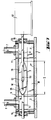
- the basic structure of the casting head 5 is shown in FIG. 2.
- the casting head 5 essentially consists of a metal body 28 which has a bore extending in the longitudinal direction of the metal body 28 and serving as a distribution conduit 29, in which the casting slot 30 opens.
- the casting slot 30 has a length L of 10 to 100 mm and a thickness D of 0.1 to 0.5 mm.
- the scraper rule 32 is fixed to the metal body 28.
- the casting substrate 1 scrolls below the casting head 5 at a constant speed, in the direction of the arrow F.
- the median supply duct 34 opens in the distribution duct 29, in the middle of the metal body 28.
- the supply duct 6 is connected by flanges to the metal body 28 and supplies the distribution duct 29 by means of the mass casting by the supply duct 34.
- the supply duct 7, which feeds the distribution duct 29 at one end of the casting head by means of the colored casting compound, is also connected by flanges to the metal body 28 Sealing plates 35 are screwed to the metal body 28 on the end faces of the latter and seal the distribution duct 29 and the slot 30 at its sides.
- a partition wall 39 in the shape of an ellipsoidal disc, is installed obliquely inside the distribution duct 29 in such a way that the flow section goes each time decreasing continuously on one side of this partition 39, while the flow section increases progressively each time to the same extent on the other side of the partition 39.
- the partition 39 arranged in the distribution duct 29 of round cross section is oriented vertically and at an angle a with respect to the axial direction of the distribution duct 29.
- the angle a is obtained directly from the desired length of the mixing section S, which defines the transition zone between the two casting masses.
- the partition wall 39 is tightly adapted to the wall of the distribution duct, for example by welding to this wall.
- the lower peripheral part 42 of the partition 39 is devoid of any connection to the wall of the distribution duct 29 and leaves a gap between the wall of the distribution duct 29 and the separation partition 39 allowing passage of the masses of which each mix with the casting mass on the other side of the partition 39.
- the optimal size of the slot 43 is a function of the viscosity of the casting masses and can be determined experimentally.
- the lower peripheral surface 43 of the partition 39 has a toothed configuration, which has proven to be particularly advantageous.
- FIG. 6 Another possible embodiment for the mixing section in the distribution duct 29 is illustrated in FIG. 6.
- a conical hollow body 46 is installed inside the distribution duct 29, the base of which is oriented towards the side which is supplied by the supply duct 37 by means of the colored casting compound.
- the conical hollow body 46 is tightly fitted to the wall of the distribution duct 29, but the base part 47 is flattened in the area 41 close to the slot 30, so that the transition from the distribution duct 29 to slot 30 is not interrupted.
- the opening 48 formed in this way therefore allows the passage of the casting mass.
- a row of passage openings 49 is provided in the wall of the conical hollow body 46, the section of which decreases in the direction of the conical tip of the hollow body 46.
- the colored casting mass exits through the openings 49, infiltrates into the colorless casting mass outside the conical hollow body and mixes with it, so that the continuous transition is obtained in this way desired between the two casting masses.
- the flow resistances for the two different casting masses are, in certain circumstances, different in the region of the mixing section 8 depending on the dimensions of the particular passage openings chosen. Since in view of uniform mixing, the hydrostatic pressure of the two casting materials is assumed to be the same in the mixing section, it is necessary, if necessary, to increase the pressure accordingly in one of the two supply lines. supply 6 or 7, to compensate for the pressure drop due to uneven flow resistances.
- Fig. 7 illustrates a variant of the casting head described first, which is distinguished by the fact that the partition 39 is installed inside the distribution duct 29 so as to be able to slide in the axial direction of this duct.
- the elliptical partition wall 39 is fixed to a positioning rod 51, for example by a welded junction 52.
- the positioning rod 51 is slidably mounted in the lateral closure plates 53 and 54, the seals 55 and 56 ensuring the sealing of the obturation of the distribution duct 29.
- the drive device 57 communicates with the positioning rod 51, and thus with the partition wall 39, the desired axial sliding movement in the direction of the double arrow 59, while the sliding surface 58 of the partition 39 cooperates with the wall of the distribution duct in the upper half of the distribution duct 29.
- the drive device 57 ensures, for example, a periodic back-and-forth movement of the partition wall 39, it is possible to obtain a wavy appearance of the separation line between the colored part and the highly transparent part of the poured layer.
- the drive device 57 can ensure periodic movement of the partition wall 39 which gives a succession of transition zones and separation lines in an arc between the colored strip and the highly transparent part of the poured layer. . It is thus possible to produce colored filter strips with a curved transition zone, which are frequently used in windshields for motor vehicles.
- the device according to the invention is advantageously used for the manufacture of polyurethane layers of high optical quality used in laminated glazing and in particular in so-called asymmetrical laminated glazing formed from a monolithic or laminated support and from a sheet of plastic material.
- asymmetrical laminated glazing formed from a monolithic or laminated support and from a sheet of plastic material.
- comprising at least one polyurethane layer as described for example in European patent publications EP 0 132 198, EP 0 131 523, EP 0 133 090, EP 0 190 517.
- These polyurethane layers obtained by reactive casting of a reaction mixture of two components, namely an isocyanate component and a polyol component can be layers having energy absorbing properties and / or scratch resistance properties and abrasion.
- reaction mixtures constituting the colored part of the layers according to the invention are generally formed from the same components as the non-colored part, the only difference being the addition in their composition of suitable coloring agents.
Claims (12)
- Vorrichtung zur Herstellung von Kunststoffschichten durch Gießen flüssiger Massen auf plane Unterlagen, mit einem einen sich über die Auftragsbreite erstreckenden Verteilerkanal aufweisenden Abstreichgießkopf, der mit einer in den Verteilerkanal mündenden und an einer zu einer Förderpumpe führenden Rohrleitung angeschlossenen Zuführungsleitung sowie mit einem sich an den Verteilerkanal anschließenden Gießspalt und mit einem Abstreichlineal versehen ist, dadurch gekennzeichnet, daß der Verteilerkanal (29) des Abstreichgießkopfes (5) mit einer weiteren Zuführungsleitung (7;37) für die Zuführung einer Gießmasse, die von der über die erste Zuführungsleitung zugeführten Gießmasse verschieden ist, versehen ist, daß in dem der gewünschten Übergangszone zwischen den beiden Gießmassen entprechenden Bereich des Verteilerkanals (29) zwischen den Zuführungsleitungen (6,7;34,37) eine Mischstrecke (S) vorgesehen ist, in der eine Mischung der beiden Gießmassen erfolgt, und daß die für die Zuführung der beiden Gießmassen dienenden Pumpen (8,9,15,16) so ausgelegt und steuerbar sind, daß sie in jedem Zeitpunkt den gleichen Druck der Gießmassen innerhalb der Mischstrecke (S) im Verteilerkanal (29) erzeugen.
- Vorrichtung nach Anspruch 1, dadurch gekennzeichnet, daß innerhalb der Mischstrecke (S) eine Trennwand (39) unter einem Winkel (a) zur Achse des Verteilerkanals (29) angeordnet ist, die zwischen der Umfangsfläche der Trennwand (39) und der Verteilerwand (29) einen Durchtrittsspalt (43) für die beiden Gießmassen bestehen läßt.
- Vorrichtung nach Anspruch 2, dadurch gekennzeichnet, daß die Trennwand (39) in dem Verteilerkanal (29) senkrecht angeordnet ist.
- Vorrichtung nach Anspruch 2 oder 3, dadurch gekennzeichnet, daß der den Durchtrittsspalt (43) bildende Teil des Umfangs der Trennwand (39) gezahnt ausgebildet ist.
- Vorrichtung nach einem der Ansprüche 2 bis 4, dadurch gekennzeichnet, daß die Trennwand (39) entlang des oberen Teils ihrer Umfangsfläche dicht an die Wand des Verteilerkanals (29) anschließt und der Durchtrittsspalt (43) entlang des unteren Teils der Umfangsfläche (42) der Trennwand gebildet ist.
- Vorrichtung nach einem der Ansprüche 2 bis 5, dadurch gekennzeichnet, daß die Trennwand (39) in dem Verteilerkanal (29) fest angeordnet ist.
- Vorrichtung nach einem der Ansprüche 2 bis 5, dadurch gekennzeichnet, daß die Trennwand (39) in dem Verteilerkanal (29) in dessen Achsrichtung verschiebbar gelagert ist.
- Vorrichtung nach Anspruch 7, dadurch gekennzeichnet, daß die Trennwand (39) mit Hilfe einer Positionierstange (51) gelagert ist, die durch eine Antriebsvorrichtung (57) in periodische Schiebbewegungen versetzbar ist.
- Vorrichtung nach Anspruch 1, dadurch gekennzeichnet, daß innerhalb der Mischstrecke (S) in dem Verteilerkanal (29) ein konischer Hohlkörper (46) angeordnet ist, dessen Basisteil (47) sich an der Wand des Verteilerkastens (29) anschließt, und in dessen Wand Durchtrittsöffnungen (49) vorgesehen sind, deren Querschnitte zur Spitze des konischen Hohlkörpers hin abnehmen.
- Vorrichtung nach Anspruch 9, dadurch gekennzeichnet, daß der Basisteil (47) des konischen Hohlkörpers (46) zu dem Zuführungskanal (37) im Endbereich des Abstreichgießkopfes hin gerichtet ist.
- Anwendung einer Vorrichtung nach einem der Ansprüche 1 bis 10 zur Herstellung einer Polyurethanschicht mit einem gefärbten Streifen und mit energieabsorbierenden Eigenschaften.
- Anwendung der Vorrichtung nach einem der Ansprüche 1 bis 11 zur Herstellung einer kratz- und abriebfesten Polyurethanschicht mit einem Farbstreifen.
Priority Applications (1)
| Application Number | Priority Date | Filing Date | Title |
|---|---|---|---|
| AT90401749T ATE100374T1 (de) | 1989-06-24 | 1990-06-21 | Vorrichtung zur herstellung von durchsichtigen kunststoffschichten, welche ein eingefaerbtes filtrierendes band in der masse aufweisen. |
Applications Claiming Priority (2)
| Application Number | Priority Date | Filing Date | Title |
|---|---|---|---|
| DE3920774 | 1989-06-24 | ||
| DE3920774A DE3920774A1 (de) | 1989-06-24 | 1989-06-24 | Giessvorrichtung zum giessen transparenter kunststoffschichten mit einem eingefaerbten filterband |
Publications (3)
| Publication Number | Publication Date |
|---|---|
| EP0406068A2 EP0406068A2 (de) | 1991-01-02 |
| EP0406068A3 EP0406068A3 (en) | 1991-03-20 |
| EP0406068B1 true EP0406068B1 (de) | 1994-01-19 |
Family
ID=6383521
Family Applications (1)
| Application Number | Title | Priority Date | Filing Date |
|---|---|---|---|
| EP90401749A Expired - Lifetime EP0406068B1 (de) | 1989-06-24 | 1990-06-21 | Vorrichtung zur Herstellung von durchsichtigen Kunststoffschichten, welche ein eingefärbtes filtrierendes Band in der Masse aufweisen |
Country Status (10)
| Country | Link |
|---|---|
| US (2) | US5044309A (de) |
| EP (1) | EP0406068B1 (de) |
| JP (1) | JP2905570B2 (de) |
| KR (1) | KR0136903B1 (de) |
| AT (1) | ATE100374T1 (de) |
| AU (1) | AU633921B2 (de) |
| BR (1) | BR9002972A (de) |
| CA (1) | CA2019476A1 (de) |
| DE (2) | DE3920774A1 (de) |
| ES (1) | ES2050397T3 (de) |
Families Citing this family (27)
| Publication number | Priority date | Publication date | Assignee | Title |
|---|---|---|---|---|
| DE69121425T2 (de) * | 1991-09-27 | 1997-01-23 | Du Pont | Zusammengesetzte beschichtung unterschiedlicher dicke mit einem farbgradienten quer zur bahnrichtung |
| EP0542635B1 (de) * | 1991-10-15 | 1999-06-09 | Eastman Kodak Company | Verfahren zum Auftragen einer magnetischen Dispersion und Vorrichtung |
| JP2537739B2 (ja) * | 1992-07-31 | 1996-09-25 | 三菱化学株式会社 | ダイコ―タ |
| DE4337826A1 (de) * | 1993-11-05 | 1995-05-11 | Cerdec Ag | Farbpaste zur Herstellung innenbedruckter Verbundglasscheiben |
| JP2547307B2 (ja) * | 1993-12-07 | 1996-10-23 | 中外炉工業株式会社 | ダイコータ |
| JP3367572B2 (ja) * | 1993-12-08 | 2003-01-14 | 日本板硝子株式会社 | 撥水被膜の形成方法 |
| US5384030A (en) * | 1994-02-15 | 1995-01-24 | General Motors Corporation | Exhaust sensor including a composite tile sensing element and methods of making the same |
| JP2665317B2 (ja) * | 1994-09-14 | 1997-10-22 | 株式会社アイジー技術研究所 | 塗装装置 |
| US5614260A (en) * | 1995-01-06 | 1997-03-25 | Xerox Corporation | Extrusion system with slide dies |
| US6544491B1 (en) | 1995-05-31 | 2003-04-08 | West Virginia University | Methods of making a carbon foam |
| US6180043B1 (en) * | 1998-01-27 | 2001-01-30 | Dai Nippon Toryo Co., Ltd. | Method of in-mold coating |
| US6482264B1 (en) * | 2000-10-26 | 2002-11-19 | General Electric Company | Systems and methods for fabrication of coating libraries |
| US6630028B2 (en) * | 2000-12-08 | 2003-10-07 | Glass Equipment Development, Inc. | Controlled dispensing of material |
| US7048964B2 (en) * | 2000-12-08 | 2006-05-23 | Ged Integrated Solutions, Inc. | Controlled dispensing of material |
| US6689218B2 (en) | 2001-10-23 | 2004-02-10 | General Electric Company | Systems for the deposition and curing of coating compositions |
| US6544334B1 (en) | 2001-10-23 | 2003-04-08 | General Electric Company | Systems and methods for the deposition and curing of coating compositions |
| ES2239897B1 (es) * | 2004-03-17 | 2006-11-16 | Jose Pallarols Clos | Recubrimiento para productos laminares y rasqueta para su aplicacion. |
| US7275570B2 (en) * | 2004-08-20 | 2007-10-02 | Glass Equipment, Inc. | Desiccant dispensing system |
| US7610681B2 (en) * | 2004-09-29 | 2009-11-03 | Ged Integrated Solutions, Inc. | Window component stock indexing |
| WO2007045589A1 (de) * | 2005-10-21 | 2007-04-26 | Robatech Ag | Vorrichtung zum flächigen auftrag eines 2-komponenten materials auf einen träger |
| DE102006009900B4 (de) * | 2006-03-03 | 2008-06-26 | Kraussmaffei Technologies Gmbh | Integrierte Systemvorrichtung zur Herstellung von Verbundkörpern |
| US7718251B2 (en) | 2006-03-10 | 2010-05-18 | Amesbury Group, Inc. | Systems and methods for manufacturing reinforced weatherstrip |
| ITTV20060124A1 (it) * | 2006-07-17 | 2008-01-18 | Hip Mitsu Srl | Struttura di testata di spalmatura, particolarmente di uno o piu' adesivi o miscele di adesivi |
| DE102008059557A1 (de) * | 2008-11-28 | 2010-06-02 | Hofmann Gmbh Maschinenfabrik Und Vertrieb | Verfahren zur Konstanthaltung der Markierungslinienbreite bei eine Markierungslinienfarbe auf eine zu markierende Oberfläche verspritzenden Markierungsmaschinen und Markierungsmaschine zur Durchführung des Verfahrens |
| US9573159B2 (en) | 2009-08-31 | 2017-02-21 | Illinois Tool Works, Inc. | Metering system for simultaneously dispensing two different adhesives from a single metering device or applicator onto a common substrate |
| US9718081B2 (en) * | 2009-08-31 | 2017-08-01 | Illinois Tool Works Inc. | Metering system for simultaneously dispensing two different adhesives from a single metering device or applicator onto a common substrate |
| US10329834B2 (en) | 2015-02-13 | 2019-06-25 | Amesbury Group, Inc. | Low compression-force TPE weatherseals |
Family Cites Families (25)
| Publication number | Priority date | Publication date | Assignee | Title |
|---|---|---|---|---|
| US2026740A (en) * | 1932-11-10 | 1936-01-07 | Celanese Corp | Extrusion apparatus |
| US3274646A (en) * | 1963-05-13 | 1966-09-27 | Rowlaud Products Inc | Apparatus for making extruded sheet material |
| US3354025A (en) * | 1964-09-18 | 1967-11-21 | Monsanto Co | Color gradated laminates |
| US3398431A (en) * | 1964-10-23 | 1968-08-27 | Nat Distillers And Chemicals C | Laminating extrusion die |
| US3448183A (en) * | 1966-08-05 | 1969-06-03 | Dow Chemical Co | Method for the preparation of multilayer film |
| US3473193A (en) * | 1967-01-03 | 1969-10-21 | Nat Distillers Chem Corp | Reciprocating multi-orificed internal die diverter |
| US3511903A (en) * | 1967-05-05 | 1970-05-12 | Dow Chemical Co | Method for extruding thermally degradable polymers |
| US3886898A (en) * | 1973-12-19 | 1975-06-03 | Burroughs Corp | Multiple, contiguous stripe, extrusion coating apparatus |
| US4001024A (en) * | 1976-03-22 | 1977-01-04 | Eastman Kodak Company | Method of multi-layer coating |
| DE2614596C3 (de) * | 1976-04-05 | 1980-03-13 | Vereinigte Glaswerke Gmbh, 5100 Aachen | Abstreichgießkopf zum Aufbringen gießfähiger Kunststoffschichten auf plane Unterlagen |
| US4095444A (en) * | 1977-06-15 | 1978-06-20 | Milliken Research Corporation | Apparatus for the application of liquids to moving materials |
| JPS5854622B2 (ja) * | 1979-02-28 | 1983-12-06 | 平岡織染株式会社 | コ−テイング装置 |
| US4272312A (en) * | 1979-11-01 | 1981-06-09 | Champion International Corporation | Process for extruding films of thermoplastic polyester film-forming materials |
| US4344990A (en) * | 1981-01-21 | 1982-08-17 | Alcan Aluminum Corporation | Process and apparatus for coating strip articles and the like |
| US4356217A (en) * | 1981-01-21 | 1982-10-26 | Alcan Aluminum Corporation | Process for producing striated surface coatings |
| US4562023A (en) * | 1981-08-18 | 1985-12-31 | Dynamit Nobel Aktiengesellschaft | Process and apparatus for producing a synthetic resin sheet having a colored band of varying color intensity |
| DE3132509C2 (de) * | 1981-08-18 | 1984-06-14 | Dynamit Nobel Ag, 5210 Troisdorf | Verfahren und Breitschlitzwerkzeug zur Herstellung einer Farbkeilfolie |
| US4476165A (en) * | 1982-06-07 | 1984-10-09 | Acumeter Laboratories, Inc. | Method of and apparatus for multi-layer viscous fluid deposition such as for the application of adhesives and the like |
| US4521457A (en) * | 1982-09-21 | 1985-06-04 | Xerox Corporation | Simultaneous formation and deposition of multiple ribbon-like streams |
| US4619802A (en) * | 1984-05-21 | 1986-10-28 | Peter Cloeren | Die with combining adaptor insert and melt-lamination process |
| US4731004A (en) * | 1984-10-12 | 1988-03-15 | Princeton Packaging, Inc. | Side-by-side co-extrusion of film using multiple materials |
| DE3517779A1 (de) * | 1985-05-17 | 1986-11-20 | Dynamit Nobel Ag, 5210 Troisdorf | Verfahren und vorrichtung zur erzeugung von gemusterten bzw. marmorierten schichten |
| IT1215422B (it) * | 1986-05-13 | 1990-02-08 | Reifenhaeuser Masch | Trafila per l'estrusione di un nastro di materia plastica del tipo termoplastico espanso. |
| EP0287861B1 (de) * | 1987-04-03 | 1992-04-29 | Asahi Glass Company Ltd. | Schicht oder Film aus transparentem Kunstharz, Verfahren zur Herstellung und Verwendung |
| DE3729266C1 (de) * | 1987-09-02 | 1988-11-10 | Bayer Ag | Verfahren und Vorrichtung zum Auftragen eines fliessfaehigen,Kunststoff,insbesondere Schaumstoff,bildenden Reaktionsgemisches |
-
1989
- 1989-06-24 DE DE3920774A patent/DE3920774A1/de not_active Withdrawn
-
1990
- 1990-05-30 AU AU56153/90A patent/AU633921B2/en not_active Ceased
- 1990-06-07 US US07/534,283 patent/US5044309A/en not_active Expired - Fee Related
- 1990-06-21 EP EP90401749A patent/EP0406068B1/de not_active Expired - Lifetime
- 1990-06-21 ES ES90401749T patent/ES2050397T3/es not_active Expired - Lifetime
- 1990-06-21 CA CA002019476A patent/CA2019476A1/fr not_active Abandoned
- 1990-06-21 AT AT90401749T patent/ATE100374T1/de active
- 1990-06-21 DE DE69006115T patent/DE69006115T2/de not_active Expired - Fee Related
- 1990-06-22 KR KR1019900009259A patent/KR0136903B1/ko not_active IP Right Cessation
- 1990-06-22 JP JP2162974A patent/JP2905570B2/ja not_active Expired - Lifetime
- 1990-06-25 BR BR909002972A patent/BR9002972A/pt not_active IP Right Cessation
-
1991
- 1991-04-03 US US07/680,141 patent/US5075139A/en not_active Expired - Fee Related
Also Published As
| Publication number | Publication date |
|---|---|
| BR9002972A (pt) | 1991-08-20 |
| US5075139A (en) | 1991-12-24 |
| KR0136903B1 (ko) | 1998-04-25 |
| JPH03109963A (ja) | 1991-05-09 |
| AU5615390A (en) | 1991-01-03 |
| KR910000323A (ko) | 1991-01-29 |
| AU633921B2 (en) | 1993-02-11 |
| ES2050397T3 (es) | 1994-05-16 |
| DE69006115D1 (de) | 1994-03-03 |
| ATE100374T1 (de) | 1994-02-15 |
| EP0406068A2 (de) | 1991-01-02 |
| US5044309A (en) | 1991-09-03 |
| JP2905570B2 (ja) | 1999-06-14 |
| CA2019476A1 (fr) | 1990-12-24 |
| DE69006115T2 (de) | 1994-07-07 |
| EP0406068A3 (en) | 1991-03-20 |
| DE3920774A1 (de) | 1991-01-10 |
Similar Documents
| Publication | Publication Date | Title |
|---|---|---|
| EP0406068B1 (de) | Vorrichtung zur Herstellung von durchsichtigen Kunststoffschichten, welche ein eingefärbtes filtrierendes Band in der Masse aufweisen | |
| EP0444998B1 (de) | Vorrichtung zum Extrudieren eines Profils auf dem Umfang einer Glasscheibe | |
| EP0171309A1 (de) | Vorbereitung eines Kunststoffes zum Extrudieren, insbesondere in Form eines kalibrierten Bandes zur Verwendung als Verbindungsmaterial und als Zwischeneinlage in Mehrfachverglasungen | |
| EP0609550B1 (de) | Vorrichtung und Verfahren zur Extrusion von Rohkautschukmischungen | |
| FR2904256A1 (fr) | Dispositif de gainage de cable a filiere mobile | |
| EP0179521B1 (de) | Einstellbarer Beschickungsblock für eine Koextrudierdüse | |
| LU82076A1 (fr) | Perfectionnements apportes aux dispositifs repartiteurs-caations pour la fabrication en continu de panneaux en matiere synthetique expansable | |
| EP0248706B1 (de) | Verfahren zur Herstellung von Verbundscheiben | |
| FR2916383A1 (fr) | Dispositif et procede d'amelioration de l'etat de surface des produits d'extrusion. | |
| WO2001074568A1 (fr) | Dispositif de soudage par ultrasons, procede et emballage associes | |
| EP0410852A1 (de) | Verfahren und Vorrichtung zur Herstellung einer inneren, thermischen Schutzschicht für ein Triebwerk | |
| FR2679797A1 (fr) | Appareil de revetement par extrusion. | |
| FR2514671A1 (fr) | Dispositif pour appliquer automatiquement un filet de colle sur l'aile d'un cadre d'une carrosserie de vehicule automobile | |
| FR2597026A1 (fr) | Dispositif de fabrication d'une plaque alveolaire, plaque alveolaire en resultant | |
| EP1440788B1 (de) | Verfahren zum Formen eines organischen optischen Elements | |
| CA2599845C (fr) | Procede de moulage d'un boyau profile sur un vitrage | |
| FR2673141A1 (fr) | Filiere reglable a galets tournants pour production d'une bande a bords inclines. | |
| EP1343624A2 (de) | Extrusionsvorrichtung zur herstellung von produkten aus kautschukmischungen | |
| FR2731378A1 (fr) | Procede de fabrication de pellicules etirees biaxialement et dispositif pour la mise en oeuvre du procede | |
| FR2507108A1 (fr) | Procede et dispositif de revetement de feuilles | |
| EP3368269B1 (de) | Vorrichtung zum extrudieren eines streifens aus elastomermaterial und verfahren zur herstellung einer hitzeschildabdeckung für einen schubkörper | |
| EP3853001A1 (de) | Koextrusionsmaschine für elastomere verbindungen und verfahren zur herstellung einer profilelementeleiste | |
| FR2491355A1 (de) | ||
| EP0978623B1 (de) | Dichtung für Plastikprofil, ihr Verlegeverfahren und ihre Verlegevorrichtung | |
| BE1006210A6 (fr) | Dispositif de separation de feuilles assemblees avec une pellicule continue. |
Legal Events
| Date | Code | Title | Description |
|---|---|---|---|
| PUAI | Public reference made under article 153(3) epc to a published international application that has entered the european phase |
Free format text: ORIGINAL CODE: 0009012 |
|
| AK | Designated contracting states |
Kind code of ref document: A2 Designated state(s): AT BE CH DE ES FR GB IT LI LU SE |
|
| PUAL | Search report despatched |
Free format text: ORIGINAL CODE: 0009013 |
|
| AK | Designated contracting states |
Kind code of ref document: A3 Designated state(s): AT BE CH DE ES FR GB IT LI LU SE |
|
| 17P | Request for examination filed |
Effective date: 19910503 |
|
| 17Q | First examination report despatched |
Effective date: 19920724 |
|
| GRAA | (expected) grant |
Free format text: ORIGINAL CODE: 0009210 |
|
| AK | Designated contracting states |
Kind code of ref document: B1 Designated state(s): AT BE CH DE ES FR GB IT LI LU SE |
|
| REF | Corresponds to: |
Ref document number: 100374 Country of ref document: AT Date of ref document: 19940215 Kind code of ref document: T |
|
| REF | Corresponds to: |
Ref document number: 69006115 Country of ref document: DE Date of ref document: 19940303 |
|
| ITF | It: translation for a ep patent filed |
Owner name: DR. ING. A. RACHELI & C. |
|
| GBT | Gb: translation of ep patent filed (gb section 77(6)(a)/1977) |
Effective date: 19940331 |
|
| REG | Reference to a national code |
Ref country code: ES Ref legal event code: FG2A Ref document number: 2050397 Country of ref document: ES Kind code of ref document: T3 |
|
| EPTA | Lu: last paid annual fee | ||
| PLBE | No opposition filed within time limit |
Free format text: ORIGINAL CODE: 0009261 |
|
| STAA | Information on the status of an ep patent application or granted ep patent |
Free format text: STATUS: NO OPPOSITION FILED WITHIN TIME LIMIT |
|
| 26N | No opposition filed | ||
| EAL | Se: european patent in force in sweden |
Ref document number: 90401749.8 |
|
| PGFP | Annual fee paid to national office [announced via postgrant information from national office to epo] |
Ref country code: CH Payment date: 19981001 Year of fee payment: 9 |
|
| PGFP | Annual fee paid to national office [announced via postgrant information from national office to epo] |
Ref country code: SE Payment date: 19990510 Year of fee payment: 10 |
|
| PGFP | Annual fee paid to national office [announced via postgrant information from national office to epo] |
Ref country code: AT Payment date: 19990610 Year of fee payment: 10 |
|
| PGFP | Annual fee paid to national office [announced via postgrant information from national office to epo] |
Ref country code: LU Payment date: 19990629 Year of fee payment: 10 |
|
| PG25 | Lapsed in a contracting state [announced via postgrant information from national office to epo] |
Ref country code: LI Free format text: LAPSE BECAUSE OF NON-PAYMENT OF DUE FEES Effective date: 19990630 Ref country code: CH Free format text: LAPSE BECAUSE OF NON-PAYMENT OF DUE FEES Effective date: 19990630 |
|
| REG | Reference to a national code |
Ref country code: CH Ref legal event code: PL |
|
| PGFP | Annual fee paid to national office [announced via postgrant information from national office to epo] |
Ref country code: GB Payment date: 20000531 Year of fee payment: 11 |
|
| PGFP | Annual fee paid to national office [announced via postgrant information from national office to epo] |
Ref country code: ES Payment date: 20000616 Year of fee payment: 11 |
|
| PG25 | Lapsed in a contracting state [announced via postgrant information from national office to epo] |
Ref country code: LU Free format text: LAPSE BECAUSE OF NON-PAYMENT OF DUE FEES Effective date: 20000621 Ref country code: AT Free format text: LAPSE BECAUSE OF NON-PAYMENT OF DUE FEES Effective date: 20000621 |
|
| PGFP | Annual fee paid to national office [announced via postgrant information from national office to epo] |
Ref country code: FR Payment date: 20000621 Year of fee payment: 11 |
|
| PG25 | Lapsed in a contracting state [announced via postgrant information from national office to epo] |
Ref country code: SE Free format text: LAPSE BECAUSE OF NON-PAYMENT OF DUE FEES Effective date: 20000622 |
|
| PGFP | Annual fee paid to national office [announced via postgrant information from national office to epo] |
Ref country code: BE Payment date: 20000629 Year of fee payment: 11 |
|
| PGFP | Annual fee paid to national office [announced via postgrant information from national office to epo] |
Ref country code: DE Payment date: 20000706 Year of fee payment: 11 |
|
| EUG | Se: european patent has lapsed |
Ref document number: 90401749.8 |
|
| PG25 | Lapsed in a contracting state [announced via postgrant information from national office to epo] |
Ref country code: GB Free format text: LAPSE BECAUSE OF NON-PAYMENT OF DUE FEES Effective date: 20010621 |
|
| PG25 | Lapsed in a contracting state [announced via postgrant information from national office to epo] |
Ref country code: ES Free format text: LAPSE BECAUSE OF NON-PAYMENT OF DUE FEES Effective date: 20010622 |
|
| PG25 | Lapsed in a contracting state [announced via postgrant information from national office to epo] |
Ref country code: BE Free format text: LAPSE BECAUSE OF NON-PAYMENT OF DUE FEES Effective date: 20010630 |
|
| BERE | Be: lapsed |
Owner name: SAINT-GOBAIN VITRAGE INTERNATIONAL Effective date: 20010630 |
|
| GBPC | Gb: european patent ceased through non-payment of renewal fee |
Effective date: 20010621 |
|
| PG25 | Lapsed in a contracting state [announced via postgrant information from national office to epo] |
Ref country code: FR Free format text: LAPSE BECAUSE OF NON-PAYMENT OF DUE FEES Effective date: 20020228 |
|
| PG25 | Lapsed in a contracting state [announced via postgrant information from national office to epo] |
Ref country code: DE Free format text: LAPSE BECAUSE OF NON-PAYMENT OF DUE FEES Effective date: 20020403 |
|
| REG | Reference to a national code |
Ref country code: ES Ref legal event code: FD2A Effective date: 20030303 |
|
| PG25 | Lapsed in a contracting state [announced via postgrant information from national office to epo] |
Ref country code: IT Free format text: LAPSE BECAUSE OF NON-PAYMENT OF DUE FEES;WARNING: LAPSES OF ITALIAN PATENTS WITH EFFECTIVE DATE BEFORE 2007 MAY HAVE OCCURRED AT ANY TIME BEFORE 2007. THE CORRECT EFFECTIVE DATE MAY BE DIFFERENT FROM THE ONE RECORDED. Effective date: 20050621 |