EP0406068B1 - Apparatus for manufacturing transparent plastic layers with a colored filtering band - Google Patents
Apparatus for manufacturing transparent plastic layers with a colored filtering band Download PDFInfo
- Publication number
- EP0406068B1 EP0406068B1 EP90401749A EP90401749A EP0406068B1 EP 0406068 B1 EP0406068 B1 EP 0406068B1 EP 90401749 A EP90401749 A EP 90401749A EP 90401749 A EP90401749 A EP 90401749A EP 0406068 B1 EP0406068 B1 EP 0406068B1
- Authority
- EP
- European Patent Office
- Prior art keywords
- casting
- distribution duct
- duct
- separating partition
- masses
- Prior art date
- Legal status (The legal status is an assumption and is not a legal conclusion. Google has not performed a legal analysis and makes no representation as to the accuracy of the status listed.)
- Expired - Lifetime
Links
Images


Classifications
-
- B—PERFORMING OPERATIONS; TRANSPORTING
- B05—SPRAYING OR ATOMISING IN GENERAL; APPLYING FLUENT MATERIALS TO SURFACES, IN GENERAL
- B05C—APPARATUS FOR APPLYING FLUENT MATERIALS TO SURFACES, IN GENERAL
- B05C11/00—Component parts, details or accessories not specifically provided for in groups B05C1/00 - B05C9/00
- B05C11/10—Storage, supply or control of liquid or other fluent material; Recovery of excess liquid or other fluent material
-
- B—PERFORMING OPERATIONS; TRANSPORTING
- B29—WORKING OF PLASTICS; WORKING OF SUBSTANCES IN A PLASTIC STATE IN GENERAL
- B29C—SHAPING OR JOINING OF PLASTICS; SHAPING OF MATERIAL IN A PLASTIC STATE, NOT OTHERWISE PROVIDED FOR; AFTER-TREATMENT OF THE SHAPED PRODUCTS, e.g. REPAIRING
- B29C41/00—Shaping by coating a mould, core or other substrate, i.e. by depositing material and stripping-off the shaped article; Apparatus therefor
- B29C41/24—Shaping by coating a mould, core or other substrate, i.e. by depositing material and stripping-off the shaped article; Apparatus therefor for making articles of indefinite length
- B29C41/32—Making multilayered or multicoloured articles
-
- B—PERFORMING OPERATIONS; TRANSPORTING
- B05—SPRAYING OR ATOMISING IN GENERAL; APPLYING FLUENT MATERIALS TO SURFACES, IN GENERAL
- B05C—APPARATUS FOR APPLYING FLUENT MATERIALS TO SURFACES, IN GENERAL
- B05C3/00—Apparatus in which the work is brought into contact with a bulk quantity of liquid or other fluent material
- B05C3/18—Apparatus in which the work is brought into contact with a bulk quantity of liquid or other fluent material only one side of the work coming into contact with the liquid or other fluent material
-
- B—PERFORMING OPERATIONS; TRANSPORTING
- B05—SPRAYING OR ATOMISING IN GENERAL; APPLYING FLUENT MATERIALS TO SURFACES, IN GENERAL
- B05C—APPARATUS FOR APPLYING FLUENT MATERIALS TO SURFACES, IN GENERAL
- B05C5/00—Apparatus in which liquid or other fluent material is projected, poured or allowed to flow on to the surface of the work
- B05C5/02—Apparatus in which liquid or other fluent material is projected, poured or allowed to flow on to the surface of the work the liquid or other fluent material being discharged through an outlet orifice by pressure, e.g. from an outlet device in contact or almost in contact, with the work
- B05C5/0254—Coating heads with slot-shaped outlet
-
- B—PERFORMING OPERATIONS; TRANSPORTING
- B29—WORKING OF PLASTICS; WORKING OF SUBSTANCES IN A PLASTIC STATE IN GENERAL
- B29C—SHAPING OR JOINING OF PLASTICS; SHAPING OF MATERIAL IN A PLASTIC STATE, NOT OTHERWISE PROVIDED FOR; AFTER-TREATMENT OF THE SHAPED PRODUCTS, e.g. REPAIRING
- B29C31/00—Handling, e.g. feeding of the material to be shaped, storage of plastics material before moulding; Automation, i.e. automated handling lines in plastics processing plants, e.g. using manipulators or robots
- B29C31/04—Feeding of the material to be moulded, e.g. into a mould cavity
- B29C31/10—Feeding of the material to be moulded, e.g. into a mould cavity of several materials
-
- B—PERFORMING OPERATIONS; TRANSPORTING
- B29—WORKING OF PLASTICS; WORKING OF SUBSTANCES IN A PLASTIC STATE IN GENERAL
- B29C—SHAPING OR JOINING OF PLASTICS; SHAPING OF MATERIAL IN A PLASTIC STATE, NOT OTHERWISE PROVIDED FOR; AFTER-TREATMENT OF THE SHAPED PRODUCTS, e.g. REPAIRING
- B29C48/00—Extrusion moulding, i.e. expressing the moulding material through a die or nozzle which imparts the desired form; Apparatus therefor
- B29C48/16—Articles comprising two or more components, e.g. co-extruded layers
- B29C48/18—Articles comprising two or more components, e.g. co-extruded layers the components being layers
- B29C48/19—Articles comprising two or more components, e.g. co-extruded layers the components being layers the layers being joined at their edges
-
- B—PERFORMING OPERATIONS; TRANSPORTING
- B32—LAYERED PRODUCTS
- B32B—LAYERED PRODUCTS, i.e. PRODUCTS BUILT-UP OF STRATA OF FLAT OR NON-FLAT, e.g. CELLULAR OR HONEYCOMB, FORM
- B32B17/00—Layered products essentially comprising sheet glass, or glass, slag, or like fibres
- B32B17/06—Layered products essentially comprising sheet glass, or glass, slag, or like fibres comprising glass as the main or only constituent of a layer, next to another layer of a specific material
- B32B17/10—Layered products essentially comprising sheet glass, or glass, slag, or like fibres comprising glass as the main or only constituent of a layer, next to another layer of a specific material of synthetic resin
- B32B17/10005—Layered products essentially comprising sheet glass, or glass, slag, or like fibres comprising glass as the main or only constituent of a layer, next to another layer of a specific material of synthetic resin laminated safety glass or glazing
- B32B17/10807—Making laminated safety glass or glazing; Apparatus therefor
- B32B17/10899—Making laminated safety glass or glazing; Apparatus therefor by introducing interlayers of synthetic resin
- B32B17/10935—Making laminated safety glass or glazing; Apparatus therefor by introducing interlayers of synthetic resin as a preformed layer, e.g. formed by extrusion
-
- B—PERFORMING OPERATIONS; TRANSPORTING
- B05—SPRAYING OR ATOMISING IN GENERAL; APPLYING FLUENT MATERIALS TO SURFACES, IN GENERAL
- B05C—APPARATUS FOR APPLYING FLUENT MATERIALS TO SURFACES, IN GENERAL
- B05C5/00—Apparatus in which liquid or other fluent material is projected, poured or allowed to flow on to the surface of the work
- B05C5/02—Apparatus in which liquid or other fluent material is projected, poured or allowed to flow on to the surface of the work the liquid or other fluent material being discharged through an outlet orifice by pressure, e.g. from an outlet device in contact or almost in contact, with the work
- B05C5/0254—Coating heads with slot-shaped outlet
- B05C5/0258—Coating heads with slot-shaped outlet flow controlled, e.g. by a valve
-
- B—PERFORMING OPERATIONS; TRANSPORTING
- B29—WORKING OF PLASTICS; WORKING OF SUBSTANCES IN A PLASTIC STATE IN GENERAL
- B29C—SHAPING OR JOINING OF PLASTICS; SHAPING OF MATERIAL IN A PLASTIC STATE, NOT OTHERWISE PROVIDED FOR; AFTER-TREATMENT OF THE SHAPED PRODUCTS, e.g. REPAIRING
- B29C41/00—Shaping by coating a mould, core or other substrate, i.e. by depositing material and stripping-off the shaped article; Apparatus therefor
- B29C41/02—Shaping by coating a mould, core or other substrate, i.e. by depositing material and stripping-off the shaped article; Apparatus therefor for making articles of definite length, i.e. discrete articles
- B29C41/12—Spreading-out the material on a substrate, e.g. on the surface of a liquid
-
- B—PERFORMING OPERATIONS; TRANSPORTING
- B29—WORKING OF PLASTICS; WORKING OF SUBSTANCES IN A PLASTIC STATE IN GENERAL
- B29C—SHAPING OR JOINING OF PLASTICS; SHAPING OF MATERIAL IN A PLASTIC STATE, NOT OTHERWISE PROVIDED FOR; AFTER-TREATMENT OF THE SHAPED PRODUCTS, e.g. REPAIRING
- B29C48/00—Extrusion moulding, i.e. expressing the moulding material through a die or nozzle which imparts the desired form; Apparatus therefor
- B29C48/03—Extrusion moulding, i.e. expressing the moulding material through a die or nozzle which imparts the desired form; Apparatus therefor characterised by the shape of the extruded material at extrusion
- B29C48/07—Flat, e.g. panels
- B29C48/08—Flat, e.g. panels flexible, e.g. films
Definitions
- the present invention relates to a casting device for applying layers of plastics suitable for casting on flat substrates, comprising a doctor blade casting head having a distribution duct extending over the application width, which is provided a supply duct opening in the distribution duct and connected to a duct leading to a supply pump, a pouring slot opening in the distribution duct and a scraper rule.
- a doctor blade casting head of this type is described in document DE-PS-26 14 596.
- the casting slot opening in the distribution duct has a relatively small thickness and relatively large length.
- the casting mass encounters a high resistance to flow in the casting slot.
- the static pressure of the casting mass is everywhere equal inside the distribution duct, so that the casting mass escapes at the same speed from the casting slot over the entire width of that and that dead zones in the system are thereby avoided.
- such a doctor blade casting head is particularly suitable for the production of homogeneous layers and films from highly transparent plastics, for example also from multi-component reaction mixtures, the reaction of which already begins inside the casting head and for which dead zones in the system will cause streaks in the transparent layer.
- Scraper casting heads of this type find a preferred field of application in the manufacture of layers and films of highly transparent polyurethane, which are used as intermediate layers and / or anti-splinter coating layers for multilayer windshields.
- the casting substrate for these layers it is possible to use either the substrate which is to be provided with the layer, or other flat substrates from which, after hardening of the casting mass, the hardened layer is removed in the form of a film.
- Windshields for motor vehicles are frequently provided, along their upper edge, with a color filter band which attenuates the rays of the sun.
- this colored filter strip is found in the thermoplastic film joining the two individual glass sheets of laminated glazing. It can be produced by coloring the film or by coextrusion of a mass of colored plastic and a mass of colorless plastic. Between the color strip and the colorless zone there is provided a transition zone in which the transparency varies continuously over a distance from 1 centimeter to several centimeters, so that the filtering properties vary in a sort of wedge in this transition zone. Such a continuous transition zone is required by the approval requirements.
- thermoplastic films having a filter band and a continuous transition zone between the highly transparent zone and the filter band can be produced using known extruders, the production of layers or film strips Filtering from reaction mixtures using a casting head has so far not been possible.
- Document EP-A-0 287 861 describes a casting device using two conduits for the supply of a casting slot of complex geometric structure comprising a mixing section.
- the device described does not relate to a doctor blade casting device and its operation with a reserve of material upstream of the casting slot due to the doctor blade.
- the object of the present invention is to develop a casting device comprising a doctor blade casting head of the aforementioned type for the production of films or plastics layers from casting materials in such a way as the production of films or layers having a filter band and a continuous transition zone between the filter band and the highly transparent field of vision of the film or layer becomes possible.
- the casting device is characterized in that the distribution duct of the doctor blade casting head is provided with another supply duct for the admission of a casting mass different from the mass of casting admitted by the first supply conduit, that in the zone of the conduit corresponding to the desired transition zone between the two casting masses is provided, between the two supply conduits, a mixing section in which a mixing of the two casting masses, and that the pumps serving the supply of the two casting masses are designed and can be controlled in such a way that at any time they produce the same pressure of the two casting masses at the same time inside the mixing section in the distribution head of the casting head.
- the two casting masses are well miscible with each other. If necessary, it must also be ensured, by suitable additions to one and / or the other of the two casting masses, that the parameters influencing the mixing properties, such as for example the surface tension of the casting masses, are mutually adapted to ensure, even in a relatively short mixing section, obtaining a homogeneous mixture.
- the device forming the mixing section inside the distribution duct can be slidably mounted in the axial direction of the distribution duct, and a drive mechanism can be provided to cause a periodic back and forth movement of this device and thus of the mixing section. In this way, it is possible to give the interface between the two casting masses, for example, the configuration of arcs which follow one another.
- a layer 2 of a reaction mixture forming the casting mass is cast on a flat casting substrate 1 using the casting device shown in FIG. 1.
- the layer 2 consists, in its marginal zone 2 ′, of a mass of colored cast in the mass having a transparency and a coloration remaining constant in a homogeneous manner.
- the transparency increases continuously in the transition zone 2 zone, so that a decreasing filtering and absorption effect is obtained in this zone.
- a film is obtained by removing layer 2 from the casting substrate 1 after it has hardened.
- the film or layer 2 is made of a polyurethane which is obtained by reaction of a polyol (component K1) and an isocyanate (component K2).
- the casting mass is applied to the casting substrate 1 using the doctor blade casting head 5.
- the casting head 5 is provided with a central connection pipe 6 through which the casting mass highly transparent casting (K1 + K2) is introduced into the casting head 5.
- the casting head is provided with another connection pipe 7.
- the connection pipe 7 provides the supply of the colored casting mass in the mass (K1 '+ K2') which is necessary for the formation of the colored marginal zone 2 '.
- the casting mass introduced into the connection line 6 and that introduced into the connection line 7 are each prepared separately.
- the component K1 is pumped by the pump 8 and the component K2 is pumped by the pump 9 into the mixing head 10. From the mixing head 10, the reaction mixture reaches, via line 11, in another mixer 12 to which line 6 is connected.
- the component K1 ' forming the casting mass for the colored marginal zone 2', is pumped by a pump 15 and the component K2 'is pumped by a pump 16 into a mixing head 17.
- the reaction mixture forming the pouring mass arrives via the pipe 18 in the mixer 19 to which the pipe 7 is connected.
- a pressure gauge 21 is connected to line 6 and a pressure gauge 22 is connected to line 7.
- the regulating unit 25 Via the signal lines 23 and 24, the actual values of the pressures prevailing in the two lines 6 and 7 are applied to the regulating unit 25.
- the effective pressures are compared continuously.
- the pumps 8, 9, 15 and 16 are subjected to fine regulation, so that the pressures prevailing in the lines 6 and 7 are always exactly equal.
- the regulating unit 25 also ensures that the periodic pressure fluctuations of the individual pumps, which are due to the pulsation of the pumps, are in phase, so that the corresponding periodic pressure fluctuations in lines 6 and 7 do not exhibit phase shift either.
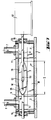
- the basic structure of the casting head 5 is shown in FIG. 2.
- the casting head 5 essentially consists of a metal body 28 which has a bore extending in the longitudinal direction of the metal body 28 and serving as a distribution conduit 29, in which the casting slot 30 opens.
- the casting slot 30 has a length L of 10 to 100 mm and a thickness D of 0.1 to 0.5 mm.
- the scraper rule 32 is fixed to the metal body 28.
- the casting substrate 1 scrolls below the casting head 5 at a constant speed, in the direction of the arrow F.
- the median supply duct 34 opens in the distribution duct 29, in the middle of the metal body 28.
- the supply duct 6 is connected by flanges to the metal body 28 and supplies the distribution duct 29 by means of the mass casting by the supply duct 34.
- the supply duct 7, which feeds the distribution duct 29 at one end of the casting head by means of the colored casting compound, is also connected by flanges to the metal body 28 Sealing plates 35 are screwed to the metal body 28 on the end faces of the latter and seal the distribution duct 29 and the slot 30 at its sides.
- a partition wall 39 in the shape of an ellipsoidal disc, is installed obliquely inside the distribution duct 29 in such a way that the flow section goes each time decreasing continuously on one side of this partition 39, while the flow section increases progressively each time to the same extent on the other side of the partition 39.
- the partition 39 arranged in the distribution duct 29 of round cross section is oriented vertically and at an angle a with respect to the axial direction of the distribution duct 29.
- the angle a is obtained directly from the desired length of the mixing section S, which defines the transition zone between the two casting masses.
- the partition wall 39 is tightly adapted to the wall of the distribution duct, for example by welding to this wall.
- the lower peripheral part 42 of the partition 39 is devoid of any connection to the wall of the distribution duct 29 and leaves a gap between the wall of the distribution duct 29 and the separation partition 39 allowing passage of the masses of which each mix with the casting mass on the other side of the partition 39.
- the optimal size of the slot 43 is a function of the viscosity of the casting masses and can be determined experimentally.
- the lower peripheral surface 43 of the partition 39 has a toothed configuration, which has proven to be particularly advantageous.
- FIG. 6 Another possible embodiment for the mixing section in the distribution duct 29 is illustrated in FIG. 6.
- a conical hollow body 46 is installed inside the distribution duct 29, the base of which is oriented towards the side which is supplied by the supply duct 37 by means of the colored casting compound.
- the conical hollow body 46 is tightly fitted to the wall of the distribution duct 29, but the base part 47 is flattened in the area 41 close to the slot 30, so that the transition from the distribution duct 29 to slot 30 is not interrupted.
- the opening 48 formed in this way therefore allows the passage of the casting mass.
- a row of passage openings 49 is provided in the wall of the conical hollow body 46, the section of which decreases in the direction of the conical tip of the hollow body 46.
- the colored casting mass exits through the openings 49, infiltrates into the colorless casting mass outside the conical hollow body and mixes with it, so that the continuous transition is obtained in this way desired between the two casting masses.
- the flow resistances for the two different casting masses are, in certain circumstances, different in the region of the mixing section 8 depending on the dimensions of the particular passage openings chosen. Since in view of uniform mixing, the hydrostatic pressure of the two casting materials is assumed to be the same in the mixing section, it is necessary, if necessary, to increase the pressure accordingly in one of the two supply lines. supply 6 or 7, to compensate for the pressure drop due to uneven flow resistances.
- Fig. 7 illustrates a variant of the casting head described first, which is distinguished by the fact that the partition 39 is installed inside the distribution duct 29 so as to be able to slide in the axial direction of this duct.
- the elliptical partition wall 39 is fixed to a positioning rod 51, for example by a welded junction 52.
- the positioning rod 51 is slidably mounted in the lateral closure plates 53 and 54, the seals 55 and 56 ensuring the sealing of the obturation of the distribution duct 29.
- the drive device 57 communicates with the positioning rod 51, and thus with the partition wall 39, the desired axial sliding movement in the direction of the double arrow 59, while the sliding surface 58 of the partition 39 cooperates with the wall of the distribution duct in the upper half of the distribution duct 29.
- the drive device 57 ensures, for example, a periodic back-and-forth movement of the partition wall 39, it is possible to obtain a wavy appearance of the separation line between the colored part and the highly transparent part of the poured layer.
- the drive device 57 can ensure periodic movement of the partition wall 39 which gives a succession of transition zones and separation lines in an arc between the colored strip and the highly transparent part of the poured layer. . It is thus possible to produce colored filter strips with a curved transition zone, which are frequently used in windshields for motor vehicles.
- the device according to the invention is advantageously used for the manufacture of polyurethane layers of high optical quality used in laminated glazing and in particular in so-called asymmetrical laminated glazing formed from a monolithic or laminated support and from a sheet of plastic material.
- asymmetrical laminated glazing formed from a monolithic or laminated support and from a sheet of plastic material.
- comprising at least one polyurethane layer as described for example in European patent publications EP 0 132 198, EP 0 131 523, EP 0 133 090, EP 0 190 517.
- These polyurethane layers obtained by reactive casting of a reaction mixture of two components, namely an isocyanate component and a polyol component can be layers having energy absorbing properties and / or scratch resistance properties and abrasion.
- reaction mixtures constituting the colored part of the layers according to the invention are generally formed from the same components as the non-colored part, the only difference being the addition in their composition of suitable coloring agents.
Abstract
Description
La présente invention concerne un dispositif de coulée destinée à appliquer des couches de matières plastiques aptes à la coulée sur des substrats plans, comportant une tête de coulée à racle présentant un conduit de distribution s'étendant sur la largeur d'application, qui est pourvue d'un conduit d'alimentation s'ouvrant dans le conduit de distribution et raccordé à une conduite aboutissant à une pompe d'alimentation, d'une fente de coulée s'ouvrant dans le conduit de distribution et d'une règle de raclage.The present invention relates to a casting device for applying layers of plastics suitable for casting on flat substrates, comprising a doctor blade casting head having a distribution duct extending over the application width, which is provided a supply duct opening in the distribution duct and connected to a duct leading to a supply pump, a pouring slot opening in the distribution duct and a scraper rule.
Une tête de coulée à racle de ce type est décrite dans le document DE-PS-26 14 596. Dans la tête de coulée à racle connue d'après ce document, la fente de coulée s'ouvrant dans le conduit de distribution présente une épaisseur relativement faible et une longueur relativement grande. De ce fait, la masse de coulée rencontre, dans la fente de coulée, une résistance élevée à l'écoulement. Ceci a pour conséquence que la pression statique de la masse de coulée est partout égale à l'intérieur du conduit de distribution, de sorte que la masse de coulée s'échappe à la même vitesse de la fente de coulée sur toute la largeur de celle-ci et que des zones mortes dans le système sont de cette manière évitées. En conséquence de cette construction, une telle tête de coulée à racle convient particulièrement pour la production de couches et de pellicules homogènes à partir de matières plastiques hautement transparentes, par exemple également à partir de mélanges de réaction à plusieurs constituants, dont la réaction débute déjà à l'intérieur de la tête de coulée et pour lesquels, des zones mortes dans le système provoquent la formation de stries dans la couche transparente.A doctor blade casting head of this type is described in document DE-PS-26 14 596. In the doctor blade casting head known from this document, the casting slot opening in the distribution duct has a relatively small thickness and relatively large length. As a result, the casting mass encounters a high resistance to flow in the casting slot. This has the consequence that the static pressure of the casting mass is everywhere equal inside the distribution duct, so that the casting mass escapes at the same speed from the casting slot over the entire width of that and that dead zones in the system are thereby avoided. As a result of this construction, such a doctor blade casting head is particularly suitable for the production of homogeneous layers and films from highly transparent plastics, for example also from multi-component reaction mixtures, the reaction of which already begins inside the casting head and for which dead zones in the system will cause streaks in the transparent layer.
Les têtes de coulée à racle de ce type trouvent un domaine d'application préféré dans la fabrication de couches et de pellicules en polyuréthane hautement transparent, qui sont utilisées comme couches intermédiaires et/ou couches de revêtement antiéclats pour des pare-brise multicouches. A titre de substrat de coulée pour ces couches, on peut utiliser soit le substrat qui doit être pourvu de la couche, soit d'autres substrats plans desquels, après durcissement de la masse de coulée, la couche durcie est enlevée sous la forme d'une pellicule.Scraper casting heads of this type find a preferred field of application in the manufacture of layers and films of highly transparent polyurethane, which are used as intermediate layers and / or anti-splinter coating layers for multilayer windshields. As the casting substrate for these layers, it is possible to use either the substrate which is to be provided with the layer, or other flat substrates from which, after hardening of the casting mass, the hardened layer is removed in the form of a film.
Les pare-brise pour véhicules automobiles sont fréquemment pourvus, le long de leur bord supérieur, d'une bande filtrante de couleur atténuant les rayons du soleil. En règle générale, cette bande filtrante de couleur se trouve dans la pellicule de matière thermoplastique unissant les deux feuilles de verre individuelles d'un vitrage feuilleté. Elle peut être élaborée par coloration de la pellicule ou par coextrusion d'une masse de matière plastique de couleur et d'une masse de matière plastique incolore. Entre la bande de couleur et la zone incolore est prévue une zone de transition dans laquelle la transparence varie de manière continue sur une distance de 1 centimètre à plusieurs centimètres, de sorte que les propriétés de filtrage varient en quelque sorte en forme de coin dans cette zone de transition. Une telle zone de transition continue est exigée par les prescriptions d'homologation.Windshields for motor vehicles are frequently provided, along their upper edge, with a color filter band which attenuates the rays of the sun. As a rule, this colored filter strip is found in the thermoplastic film joining the two individual glass sheets of laminated glazing. It can be produced by coloring the film or by coextrusion of a mass of colored plastic and a mass of colorless plastic. Between the color strip and the colorless zone there is provided a transition zone in which the transparency varies continuously over a distance from 1 centimeter to several centimeters, so that the filtering properties vary in a sort of wedge in this transition zone. Such a continuous transition zone is required by the approval requirements.
Alors que des pellicules en matières thermoplastiques présentant une bande filtrante et une zone de transition continue entre la zone hautement transparente et la bande filtrante peuvent être fabriquées à l'aide d'extrudeuses connues, la fabrication de couches ou de pellicules à bande filtrante à partir de mélanges de réaction à l'aide d'une tête de coulée n'est jusqu à présent pas possible.While thermoplastic films having a filter band and a continuous transition zone between the highly transparent zone and the filter band can be produced using known extruders, the production of layers or film strips Filtering from reaction mixtures using a casting head has so far not been possible.
Le document EP-A-0 287 861 décrit un dispositif de coulée utilisant deux conduits pour l'alimentation d'une fente de coulée de structure géométrique complexe comportant une section de mélange.Document EP-A-0 287 861 describes a casting device using two conduits for the supply of a casting slot of complex geometric structure comprising a mixing section.
Dans ce dispositif il n'est pas prévu de racle empêchant un écoulement direct de la matière coulée sur le support.In this device there is no doctor blade preventing direct flow of the material poured onto the support.
Le dispositif décrit concerne pas un dispositif de coulée à racle et son fonctionnement avec une réserve de matière en amont de la fente de coulée du fait de la racle.The device described does not relate to a doctor blade casting device and its operation with a reserve of material upstream of the casting slot due to the doctor blade.
La présente invention a pour but de développer un dispositif de coulée comportant une tête de coulée à racle du type précité pour la fabrication de pellicules ou de couches de matières plastiques à partir de masses de coulée d'une manière telle que la fabrication de pellicules ou de couches présentant une bande filtrante et une zone de transition continue entre la bande filtrante et le champ de vision hautement transparent de la pellicule ou de la couche devienne possible.The object of the present invention is to develop a casting device comprising a doctor blade casting head of the aforementioned type for the production of films or plastics layers from casting materials in such a way as the production of films or layers having a filter band and a continuous transition zone between the filter band and the highly transparent field of vision of the film or layer becomes possible.
Le dispositif de coulée conforme à l'invention est caractérisé en ce que le conduit de distribution de la tête de coulée à racle est pourvu d'un autre conduit d'alimentation pour l'admission d'une masse de coulée différente de la masse de coulée admise par le premier conduit d'alimentation, que dans la zone du conduit correspondant à la zone de transition souhaitée entre les deux masses de coulée est prévue, entre les deux conduits d'alimentation, une section de mélange dans laquelle s'opère un mélange des deux masses de coulée, et que les pompes servant à l'alimentation des deux masses de coulée sont conçues et peuvent être commandées d'une manière telle qu'à tout moment, elles produisent la même pression des deux masses de coulée à l'intérieur de la section de mélange dans le conduit de distribution de la tête de coulée.The casting device according to the invention is characterized in that the distribution duct of the doctor blade casting head is provided with another supply duct for the admission of a casting mass different from the mass of casting admitted by the first supply conduit, that in the zone of the conduit corresponding to the desired transition zone between the two casting masses is provided, between the two supply conduits, a mixing section in which a mixing of the two casting masses, and that the pumps serving the supply of the two casting masses are designed and can be controlled in such a way that at any time they produce the same pressure of the two casting masses at the same time inside the mixing section in the distribution head of the casting head.
Il s'est avéré que des couches ou des pellicules présentant une bande filtrante et une zone de transition irréprochable inchangée peuvent être réalisées à l'aide d'une tête de coulée à racle et des particularités caractéristiques de l'invention. Une importance particulière doit alors être attribuée à la section de mélange dans le conduit de distribution qui peut, en principe, être d'une configuration différente, pour autant que soit satisfaite la condition que la section transversale d'écoulement pour chacune des deux masses de coulée aille en diminuant en direction de l'autre masse de coulée, chaque fois à partir d'une aire maximale jusqu'à une aire minimale. La commande précise de la pression des pompes d'alimentation pour les deux masses de coulée différentes est également très importante, car les plus petites différences de pression provoquent déjà des irrégularités dans la largeur et l'allure de la zone de transition. Dans le cas de pompes pulsantes, par exemple, il faut garantir l'obtention de mouvements en phase des pistons des pompes.It has been found that layers or films having a filtering band and an unchanged flawless transition zone can be produced using a doctor blade head and characteristic features of the invention. Particular importance must then be assigned to the mixing section in the distribution duct which can, in principle, be of a different configuration, provided that the condition that the flow cross section for each of the two masses of material is satisfied. casting goes decreasing towards the other casting mass, each time from a maximum area to a minimum area. Precise control of the pressure of the feed pumps for both masses of different casting is also very important, as the smallest pressure differences already cause irregularities in the width and shape of the transition zone. In the case of pulsating pumps, for example, it is necessary to guarantee that phase movements of the pistons of the pumps are obtained.
Pour réaliser une zone de transition continue irréprochable entre la bande filtrante et la zone hautement transparente, il est important, en outre, que les deux masses de coulée soient bien miscibles entre elles. Le cas échéant, il faut également assurer, par des additions adéquates à l'une et/ou l'autre des deux masses de coulée, que les paramètres influençant les propriétés de mélange, comme par exemple la tension superficielle des masses de coulée, soient mutuellement adaptés pour assurer, même dans une section de mélange relativement courte, l'obtention d'un mélange homogène.To achieve a flawless continuous transition zone between the filter band and the highly transparent zone, it is also important that the two casting masses are well miscible with each other. If necessary, it must also be ensured, by suitable additions to one and / or the other of the two casting masses, that the parameters influencing the mixing properties, such as for example the surface tension of the casting masses, are mutually adapted to ensure, even in a relatively short mixing section, obtaining a homogeneous mixture.
Suivant un développement avantageux de l'invention, le dispositif formant la section de mélange à l'intérieur du conduit de distribution peut être monté à coulissement dans le sens axial du conduit de distribution, et un mécanisme d'entraînement peut être prévu pour provoquer un mouvement de va-et-vient périodique de ce dispositif et ainsi de la section de mélange. De cette manière, il est possible de conférer à l'interface entre les deux masses de coulée, par exemple, la configuration d'arcs de cercle qui se suivent.According to an advantageous development of the invention, the device forming the mixing section inside the distribution duct can be slidably mounted in the axial direction of the distribution duct, and a drive mechanism can be provided to cause a periodic back and forth movement of this device and thus of the mixing section. In this way, it is possible to give the interface between the two casting masses, for example, the configuration of arcs which follow one another.
Il est ainsi possible de fabriquer des couches ou des pellicules présentant des bandes filtrantes, dont la ligne de délimitation s'étend en arc de cercle parallèlement au bord supérieur du pare-brise, ce qui, en règle générale, est souhaité pour des raisons d'esthétique.It is thus possible to manufacture layers or films having filtering bands, the delimitation line of which extends in an arc of a circle parallel to the upper edge of the windshield, which, as a general rule, is desired for reasons of 'aesthetic.
D'autres particularités de l'invention ressortiront des revendications dépendantes et de la description suivante de divers exemples de réalisation du dispositif de coulée conforme à l'invention.Other features of the invention will emerge from the dependent claims and from the following description of various embodiments of the casting device according to the invention.
Dans les dessins annexés :
- La fig. 1 est une vue d'ensemble schématique d'un dispositif de coulée conforme à l'invention pendant l'enduction d'un substrat de coulée ;
- La fig. 2 est une vue en coupe, à plus grande échelle, suivant la ligne II-II de la fig. 1 ;
- Les fig. 3 à 5 montrent diverses vues en coupe d'une première forme d'exécution d'une tête de coulée ;
- La fig. 6 est une vue en coupe longitudinale verticale d'une autre forme d'exécution d'une tête de coulée, et
- La fig. 7 est également une vue en coupe longitudinale verticale d'une forme d'exécution d'une tête de coulée, dans laquelle la position de la section de mélange est déplaçable par coulissement dans le sens axial.
- Fig. 1 is a schematic overview of a casting device according to the invention during the coating of a casting substrate;
- Fig. 2 is a sectional view, on a larger scale, along the line II-II of FIG. 1;
- Figs. 3 to 5 show various sectional views of a first embodiment of a casting head;
- Fig. 6 is a view in vertical longitudinal section of another embodiment of a casting head, and
- Fig. 7 is also a view in vertical longitudinal section of an embodiment of a casting head, in which the position of the mixing section is movable by sliding in the axial direction.
Une couche 2 d'un mélange de réaction formant la masse de coulée est coulée sur un substrat de coulée plan 1 à l'aide du dispositif de coulée représenté sur la fig. 1. La couche 2 est constituée, dans sa zone marginale 2', d'une masse de coulée colorée dans la masse présentant une transparence et une coloration restant constantes de manière homogène.A
La transparence augmente de manière continue dans la zone de transition 2˝, de sorte qu'un effet de filtrage et d'absorption décroissant est obtenu dans cette zone.The transparency increases continuously in the
Dans le cas représenté, une pellicule est obtenue par enlèvement de la couche 2 du substrat de coulée 1 après son durcissement. La pellicule ou la couche 2 est faite d'un polyuréthane qui est obtenu par réaction d'un polyol (constituant K1) et d'un isocyanate (constituant K2).In the case shown, a film is obtained by removing
L'application de la masse de coulée sur le substrat de coulée 1 s'effectue à l'aide de la tête de coulée à racle 5. La tête de coulée 5 est pourvue d'une conduite de raccordement médiane 6 par laquelle la masse de coulée hautement transparente (K1 + K2) est introduite dans la tête de coulée 5. Dans la section d'extrémité 5', la tête de coulée est pourvue d'une autre conduite de raccordement 7. La conduite de raccordement 7 assure l'alimentation de la masse de coulée colorée dans la masse (K1' + K2') qui est nécessaire pour la formation de la zone marginale colorée 2'.The casting mass is applied to the
La masse de coulée introduite dans la conduite de raccordement 6 et celle introduite dans la conduite de raccordement 7 sont chaque fois préparées séparément. Pour la préparation de la masse de coulée hautement transparente introduite dans la tête de coulée 5 par la conduite 6, le constituant K1 est pompé par la pompe 8 et le constituant K2 est pompé par la pompe 9 dans la tête de mélange 10. A partir de la tête de mélange 10, le mélange de réaction parvient, par la conduite 11, dans un autre mélangeur 12 auquel la conduite 6 se raccorde.The casting mass introduced into the
D'une manière analogue, le constituant K1', formant la masse de coulée pour la zone marginale colorée 2', est pompé par une pompe 15 et le constituant K2' est pompé par une pompe 16 dans une tête de mélange 17.Similarly, the component K1 ', forming the casting mass for the colored marginal zone 2', is pumped by a
A partir de la tête de mélange 17, le mélange de réaction formant la masse de coulée parvient par la conduite 18 dans le mélangeur 19 auquel est raccordée la conduite 7.From the
Un manomètre 21 est raccordé à la conduite 6 et un manomètre 22 est raccordé à la conduite 7. Par l'intermédiaire des lignes de signalisation 23 et 24, les valeurs réelles des pressions régnant dans les deux conduites 6 et 7 sont appliquées à l'unité de régulation 25. Dans cette unité de régulation 25, les pressions effectives sont comparées de manière continue. Par l'intermédiaire des lignes de commande 26, 27, 28 et 29, les pompes 8, 9, 15 et 16 sont soumises à une régulation fine, de telle sorte que les pressions régnant dans les conduites 6 et 7 soient toujours exactement égales. Lorsque les pompes 8, 9, 15 et 16 sont des pompes pulsantes, par exemple des pompes à pistons, l'unité de régulation 25 assure également que les fluctuations de pression périodiques des pompes individuelles, qui sont dues à la pulsation des pompes, soient en phase, afin que les fluctuations de pression périodiques correspondantes dans les conduites 6 et 7 ne présentent pas non plus de déphasage.A
La structure fondamentale de la tête de coulée 5 est indiquée sur la fig. 2. La tête de coulée 5 est essentiellement constituée d'un corps métallique 28 qui présente un alésage s'étendant dans le sens longitudinal du corps métallique 28 et servant de conduit de distribution 29, dans lequel s'ouvre la fente de coulée 30. La fente de coulée 30 a une longueur L de 10 à 100 mm et une épaisseur D de 0,1 à 0,5 mm. La règle de raclage 32 est fixée au corps métallique 28. Le substrat de coulée 1 défile en dessous de la tête de coulée 5 à une vitesse constante, dans le sens de la flèche F.The basic structure of the
Le conduit d'alimentation médian 34 s'ouvre dans le conduit de distribution 29, au milieu du corps métallique 28. La conduite d'alimentation 6 est raccordée par brides au corps métallique 28 et alimente le conduit de distribution 29 au moyen de la masse de coulée par le conduit d'alimentation 34. La conduite d'alimentation 7, qui alimente le conduit de distribution 29 à une extrémité de la tête de coulée au moyen de la masse de coulée colorée, est également raccordée par brides au corps métallique 28. Des plaques obturatrices 35 sont vissées au corps métallique 28 sur les faces d'about de celui-ci et obturent le conduit de distribution 29 et la fente 30 au niveau de ses côtés.The
Comme les fig. 3 à 5 le montrent en détail, dans le conduit de distribution 29, entre le conduit d'alimentation 37, auquel est raccordée la conduite 7 pour la masse de coulée colorée, et le conduit d'alimentation médian 34, auquel est raccordée la conduite 6, se trouve une section de mélange 8 dans laquelle une transition continue entre les deux masses de coulée différentes est formée, c'est-à-dire dans laquelle les deux masses de coulée se mélangent d'une façon telle que la transition continue souhaitée soit formée.As in fig. 3 to 5 show it in detail, in the
A cet effet, une cloison de séparation 39, ayant la forme d'un disque ellipsoïdal, est installée obliquement à l'intérieur du conduit de distribution 29 d'une manière telle que la section d'écoulement aille chaque fois en diminuant de manière continue d'un côté de cette cloison de séparation 39, tandis que la section d'écoulement augmente chaque fois progressivement dans la même mesure de l'autre côté de la cloison de séparation 39. La cloison de séparation 39 disposée dans le conduit de distribution 29 de section transversale ronde est orientée verticalement et ce sous un angle a par rapport à la direction axiale du conduit de distribution 29.For this purpose, a
L'angle a est obtenu directement à partir de la longueur souhaitée de la section de mélange S, qui définit la zone de transition entre les deux masses de coulée. Le long de la partie supérieure 40 de sa surface périphérique, c'est-à-dire sur la section par laquelle elle s'applique contre la moitié supérieure du conduit de distribution 29, la cloison de séparation 39 est adaptée de manière étanche à la paroi du conduit de distribution, par exemple par soudage à cette paroi. La partie périphérique inférieure 42 de la cloison de séparation 39 est dépourvue de toute liaison à la paroi du conduit de distribution 29 et laisse subsister, entre la paroi du conduit de distribution 29 et la cloison de séparation 39, une fente livrant passage aux masses de coulée qui se mélangent chacune avec la masse de coulée se trouvant de l'autre côté de la cloison de séparation 39.The angle a is obtained directly from the desired length of the mixing section S, which defines the transition zone between the two casting masses. Along the
La dimension optimale de la fente 43 est fonction de la viscosité des masses de coulée et peut être déterminée expérimentalement. Dans le cas représenté, la surface périphérique inférieure 43 de la cloison de séparation 39 présente une configuration dentée, ce qui s'est avéré particulièrement avantageux.The optimal size of the
Une autre forme d'exécution possible pour la section de mélange dans le conduit de distribution 29 est illustrée sur la fig. 6. Dans ce cas, est installé à l'intérieur du conduit de distribution 29 un corps creux conique 46 dont la base est orientée vers le côté qui est alimenté par le conduit d'alimentation 37 au moyen de la masse de coulée colorée. Au niveau de sa base 47, le corps creux conique 46 est adapté de manière étanche à la paroi du conduit de distribution 29, mais la partie de base 47 est aplatie dans la zone 41 proche de la fente 30, de sorte que la transition du conduit de distribution 29 à la fente 30 n'est pas interrompue. L'ouverture 48 formée de cette façon permet donc le passage de la masse de coulée.Another possible embodiment for the mixing section in the
Dans la paroi du corps creux conique 46 est prévue une rangée d'ouvertures de passage 49, dont la section va en diminuant en direction de la pointe conique du corps creux 46.A row of
La masse de coulée colorée sort par les ouvertures 49, s'infiltre dans la masse de coulée incolore présente à l'extérieur du corps creux conique et se mélange à celle-ci, de sorte que l'on obtient de cette façon la transition continue souhaitée entre les deux masses de coulée.The colored casting mass exits through the
Dans cette forme d'exécution représentée sur la fig. 6, les résistances à l'écoulement pour les deux masses de coulée différentes sont, dans certaines circonstances, différentes dans la zone de la section de mélange 8 en fonction des dimensions des ouvertures de passage particulières choisies. Etant donné qu'en vue d'un mélange uniforme, la pression hydrostatique des deux masses de coulée est présumée être la même dans la section de mélange, il faut, le cas échéant, augmenter la pression en conséquence dans une des deux conduites d'alimentation 6 ou 7, afin de compenser la perte de charge due aux résistances à l'écoulement inégales.In this embodiment shown in FIG. 6, the flow resistances for the two different casting masses are, in certain circumstances, different in the region of the mixing section 8 depending on the dimensions of the particular passage openings chosen. Since in view of uniform mixing, the hydrostatic pressure of the two casting materials is assumed to be the same in the mixing section, it is necessary, if necessary, to increase the pressure accordingly in one of the two supply lines.
La Fig. 7 illustre une variante de la tête de coulée décrite en premier lieu, qui se distingue par le fait que la cloison de séparation 39 est installée à l'intérieur du conduit de distribution 29 de manière à pouvoir coulisser dans le sens axial de ce conduit. A cet effet, la cloison de séparation elliptique 39 est fixée sur une tige de positionnement 51, par exemple par une jonction soudée 52. La tige de positionnement 51 est montée à coulissement dans les plaques d'obturation latérales 53 et 54, les joints 55 et 56 assurant l'étanchéité de l'obturation du conduit de distribution 29. Le dispositif d'entraînement 57 communique à la tige de positionnement 51, et ainsi à la cloison de séparation 39, le mouvement de coulissement axial souhaité dans le sens de la double flèche 59, tandis que la surface de glissement 58 de la cloison de séparation 39 coopère avec la paroi du conduit de distribution dans la moitié supérieure du conduit de distribution 29.Fig. 7 illustrates a variant of the casting head described first, which is distinguished by the fact that the
Lorsque le dispositif d'entrainement 57 assure, par exemple, un mouvement de va-et-vient périodique de la cloison de séparation 39, on peut obtenir une allure ondulée de la ligne de séparation entre la partie colorée et la partie hautement transparente de la couche coulée. De même, le dispositif d'entraînement 57 peut assurer un mouvement périodique de la cloison de séparation 39 qui donne une succession de zones de transition et de lignes de séparation en arc de cercle entre la bande colorée et la partie hautement transparente de la couche coulée. On peut ainsi réaliser des bandes filtrantes colorées à zone de transition courbe, qui sont fréquemment utilisées dans des pare-brise pour véhicules automobiles.When the
Le dispositif selon l'invention est avantageusement utilisé pour la fabrication de couches de polyuréthane de haute qualité optique utilisé dans les vitrages feuilletés et en particulier dans les vitrages feuilletés dits asymétriques formés d'un support monolithique ou feuilleté et d'une feuille de matière plastique comprenant au moins une couche en polyuréthane comme décrit par exemple dans les publications de brevets européens EP 0 132 198, EP 0 131 523, EP 0 133 090, EP 0 190 517.The device according to the invention is advantageously used for the manufacture of polyurethane layers of high optical quality used in laminated glazing and in particular in so-called asymmetrical laminated glazing formed from a monolithic or laminated support and from a sheet of plastic material. comprising at least one polyurethane layer as described for example in European
Ces couches de polyuréthane obtenues par coulée réactive d'un mélange réactionnel de deux composants, à savoir un composant isocyanate et un composant polyol peuvent être des couches ayant des propriétés d'absorbeur d'énergie et/ou des propriétés de résistance à la rayure et à l'abrasion.These polyurethane layers obtained by reactive casting of a reaction mixture of two components, namely an isocyanate component and a polyol component can be layers having energy absorbing properties and / or scratch resistance properties and abrasion.
Les mélanges réactionnels constituants la partie colorée des couches selon l'invention sont formés généralement à partir des mêmes composants que la partie non colorée, la seule différence étant l'ajout dans leur composition d'agents colorants adaptés.The reaction mixtures constituting the colored part of the layers according to the invention are generally formed from the same components as the non-colored part, the only difference being the addition in their composition of suitable coloring agents.
Claims (12)
- Device for the production of sheets or films of plastics materials by casting liquid masses onto plane substrates, the device comprising a scraper casting head having a distribution duct extending across the width of application, which is provided with a feed duct leading into the distribution duct and connected to a pipe leading from a feed pump, a casting slot opening into the distribution duct and a scraper blade, characterized in that the distribution duct (29) of the scraper casting head (5) is provided with another feed duct (7; 37) for the entry of a casting mass different from the casting mass entering through the first feed duct, that in the region of the distribution duct (29) corresponding to the desired transition zone between the two casting masses there is provided, between the two feed ducts (6, 7; 34, 37), a mixing section (S), in which a mixing of the two casting masses takes place, and that the pumps (8, 9, 15, 16) serving for supplying the two casting masses are designed and can be controlled in such a way that, at any instant, they produce the same pressure in the two casting masses inside the mixing section (S) in the distribution duct (29).
- Device according to Claim 1, characterized in that, inside the mixing section (S), there is installed a separating partition (39) at an angle (a) to the axis of the distribution duct (29), which leaves, between the peripheral surface of the separating partition (39) and the wall face of the distribution duct (29), a passage slit (43) for the two casting masses.
- Device according to Claim 2, characterized in that the separating partition (39) is disposed vertically in the distribution duct (29).
- Device according to Claim 2 or 3, characterized in that the portion of the periphery of the separating partition (39) forming the passage slit (43) has a toothed configuration.
- Device according to one of Claims 2 to 4, characterized in that the separating partition (39) is applied in sealing manner against the wall face of the distribution duct (29) along the upper part of its peripheral surface and the passage slit (43) is formed along the lower part of the peripheral surface (42) of the separating partition.
- Device according to one of Claims 2 to 5, characterized in that the separating partition (39) is mounted fixed in the distribution duct (29).
- Device according to one of Claims 2 to 5, characterized in that the separating partition (39) is mounted slidably in the distribution duct (29) in the axial direction of that duct.
- Device according to Claim 7, characterized in that the separating partition (39) is mounted by means of a positioning rod (51) which can be given periodic sliding movements by a drive device (57).
- Device according to Claim 1, characterized in that, within the mixing section (S) in the distribution duct (29), there is installed a hollow conical body (46), the base portion (47) of which is applied against the wall of the distribution duct (29) and in the wall of which there are provided passage openings (49), the sizes of which decrease towards the apex of the conical hollow body.
- Device according to Claim 9, characterized in that the base portion (47) of the hollow conical body (46) faces towards the feed duct (37) in the end zone of the scraper casting head.
- Application of the device according to one of Claims 1 to 10 to the production of a film of polyurethane having a coloured band and having energy-absorber properties.
- Application of the device according to one of Claims 1 to 11 to the production of a polyurethane film having a coloured band and having properties of scratch resistance and abrasion resistance.
Priority Applications (1)
| Application Number | Priority Date | Filing Date | Title |
|---|---|---|---|
| AT90401749T ATE100374T1 (en) | 1989-06-24 | 1990-06-21 | DEVICE FOR THE MANUFACTURE OF TRANSPARENT PLASTIC COATINGS, WHICH HAVE A COLORED FILTERING TAPE IN THE MASS. |
Applications Claiming Priority (2)
| Application Number | Priority Date | Filing Date | Title |
|---|---|---|---|
| DE3920774 | 1989-06-24 | ||
| DE3920774A DE3920774A1 (en) | 1989-06-24 | 1989-06-24 | CASTING DEVICE FOR CASTING TRANSPARENT PLASTIC LAYERS WITH A COLORED FILTER TAPE |
Publications (3)
| Publication Number | Publication Date |
|---|---|
| EP0406068A2 EP0406068A2 (en) | 1991-01-02 |
| EP0406068A3 EP0406068A3 (en) | 1991-03-20 |
| EP0406068B1 true EP0406068B1 (en) | 1994-01-19 |
Family
ID=6383521
Family Applications (1)
| Application Number | Title | Priority Date | Filing Date |
|---|---|---|---|
| EP90401749A Expired - Lifetime EP0406068B1 (en) | 1989-06-24 | 1990-06-21 | Apparatus for manufacturing transparent plastic layers with a colored filtering band |
Country Status (10)
| Country | Link |
|---|---|
| US (2) | US5044309A (en) |
| EP (1) | EP0406068B1 (en) |
| JP (1) | JP2905570B2 (en) |
| KR (1) | KR0136903B1 (en) |
| AT (1) | ATE100374T1 (en) |
| AU (1) | AU633921B2 (en) |
| BR (1) | BR9002972A (en) |
| CA (1) | CA2019476A1 (en) |
| DE (2) | DE3920774A1 (en) |
| ES (1) | ES2050397T3 (en) |
Families Citing this family (27)
| Publication number | Priority date | Publication date | Assignee | Title |
|---|---|---|---|---|
| DE69121425T2 (en) * | 1991-09-27 | 1997-01-23 | Du Pont | COMPOSED COATING OF DIFFERENT THICKNESS WITH A COLOR GRADIENT CROSS TO THE WAY DIRECTION |
| EP0542635B1 (en) * | 1991-10-15 | 1999-06-09 | Eastman Kodak Company | Magnetic dispersion coating method and apparatus having high shear regions |
| JP2537739B2 (en) * | 1992-07-31 | 1996-09-25 | 三菱化学株式会社 | Die coater |
| DE4337826A1 (en) * | 1993-11-05 | 1995-05-11 | Cerdec Ag | Color paste for the production of internally printed laminated glass panes |
| JP2547307B2 (en) * | 1993-12-07 | 1996-10-23 | 中外炉工業株式会社 | Die coater |
| JP3367572B2 (en) * | 1993-12-08 | 2003-01-14 | 日本板硝子株式会社 | Method of forming water-repellent coating |
| US5384030A (en) * | 1994-02-15 | 1995-01-24 | General Motors Corporation | Exhaust sensor including a composite tile sensing element and methods of making the same |
| JP2665317B2 (en) * | 1994-09-14 | 1997-10-22 | 株式会社アイジー技術研究所 | Painting equipment |
| US5614260A (en) * | 1995-01-06 | 1997-03-25 | Xerox Corporation | Extrusion system with slide dies |
| US6544491B1 (en) | 1995-05-31 | 2003-04-08 | West Virginia University | Methods of making a carbon foam |
| US6180043B1 (en) * | 1998-01-27 | 2001-01-30 | Dai Nippon Toryo Co., Ltd. | Method of in-mold coating |
| US6482264B1 (en) * | 2000-10-26 | 2002-11-19 | General Electric Company | Systems and methods for fabrication of coating libraries |
| US6630028B2 (en) * | 2000-12-08 | 2003-10-07 | Glass Equipment Development, Inc. | Controlled dispensing of material |
| US7048964B2 (en) * | 2000-12-08 | 2006-05-23 | Ged Integrated Solutions, Inc. | Controlled dispensing of material |
| US6689218B2 (en) | 2001-10-23 | 2004-02-10 | General Electric Company | Systems for the deposition and curing of coating compositions |
| US6544334B1 (en) | 2001-10-23 | 2003-04-08 | General Electric Company | Systems and methods for the deposition and curing of coating compositions |
| ES2239897B1 (en) * | 2004-03-17 | 2006-11-16 | Jose Pallarols Clos | COATING FOR LAMINARY PRODUCTS AND RASQUETTE FOR APPLICATION. |
| US7275570B2 (en) * | 2004-08-20 | 2007-10-02 | Glass Equipment, Inc. | Desiccant dispensing system |
| US7610681B2 (en) * | 2004-09-29 | 2009-11-03 | Ged Integrated Solutions, Inc. | Window component stock indexing |
| WO2007045589A1 (en) * | 2005-10-21 | 2007-04-26 | Robatech Ag | Device for spreading a two component material on a carrier in the form of a web |
| DE102006009900B4 (en) * | 2006-03-03 | 2008-06-26 | Kraussmaffei Technologies Gmbh | Integrated system device for producing composite bodies |
| US7718251B2 (en) | 2006-03-10 | 2010-05-18 | Amesbury Group, Inc. | Systems and methods for manufacturing reinforced weatherstrip |
| ITTV20060124A1 (en) * | 2006-07-17 | 2008-01-18 | Hip Mitsu Srl | CUTTING HEAD STRUCTURE, PARTICULARLY OF ONE OR MORE ADHESIVES OR MIXTURES OF STICKERS |
| DE102008059557A1 (en) * | 2008-11-28 | 2010-06-02 | Hofmann Gmbh Maschinenfabrik Und Vertrieb | Method for keeping constant the marking line width at a marking line color on a marking surface to be marked marking machines and marking machine for performing the method |
| US9573159B2 (en) | 2009-08-31 | 2017-02-21 | Illinois Tool Works, Inc. | Metering system for simultaneously dispensing two different adhesives from a single metering device or applicator onto a common substrate |
| US9718081B2 (en) * | 2009-08-31 | 2017-08-01 | Illinois Tool Works Inc. | Metering system for simultaneously dispensing two different adhesives from a single metering device or applicator onto a common substrate |
| US10329834B2 (en) | 2015-02-13 | 2019-06-25 | Amesbury Group, Inc. | Low compression-force TPE weatherseals |
Family Cites Families (25)
| Publication number | Priority date | Publication date | Assignee | Title |
|---|---|---|---|---|
| US2026740A (en) * | 1932-11-10 | 1936-01-07 | Celanese Corp | Extrusion apparatus |
| US3274646A (en) * | 1963-05-13 | 1966-09-27 | Rowlaud Products Inc | Apparatus for making extruded sheet material |
| US3354025A (en) * | 1964-09-18 | 1967-11-21 | Monsanto Co | Color gradated laminates |
| US3398431A (en) * | 1964-10-23 | 1968-08-27 | Nat Distillers And Chemicals C | Laminating extrusion die |
| US3448183A (en) * | 1966-08-05 | 1969-06-03 | Dow Chemical Co | Method for the preparation of multilayer film |
| US3473193A (en) * | 1967-01-03 | 1969-10-21 | Nat Distillers Chem Corp | Reciprocating multi-orificed internal die diverter |
| US3511903A (en) * | 1967-05-05 | 1970-05-12 | Dow Chemical Co | Method for extruding thermally degradable polymers |
| US3886898A (en) * | 1973-12-19 | 1975-06-03 | Burroughs Corp | Multiple, contiguous stripe, extrusion coating apparatus |
| US4001024A (en) * | 1976-03-22 | 1977-01-04 | Eastman Kodak Company | Method of multi-layer coating |
| DE2614596C3 (en) * | 1976-04-05 | 1980-03-13 | Vereinigte Glaswerke Gmbh, 5100 Aachen | Skimmer head for applying castable plastic layers on flat surfaces |
| US4095444A (en) * | 1977-06-15 | 1978-06-20 | Milliken Research Corporation | Apparatus for the application of liquids to moving materials |
| JPS5854622B2 (en) * | 1979-02-28 | 1983-12-06 | 平岡織染株式会社 | coating equipment |
| US4272312A (en) * | 1979-11-01 | 1981-06-09 | Champion International Corporation | Process for extruding films of thermoplastic polyester film-forming materials |
| US4344990A (en) * | 1981-01-21 | 1982-08-17 | Alcan Aluminum Corporation | Process and apparatus for coating strip articles and the like |
| US4356217A (en) * | 1981-01-21 | 1982-10-26 | Alcan Aluminum Corporation | Process for producing striated surface coatings |
| US4562023A (en) * | 1981-08-18 | 1985-12-31 | Dynamit Nobel Aktiengesellschaft | Process and apparatus for producing a synthetic resin sheet having a colored band of varying color intensity |
| DE3132509C2 (en) * | 1981-08-18 | 1984-06-14 | Dynamit Nobel Ag, 5210 Troisdorf | Method and slot tool for producing a color wedge film |
| US4476165A (en) * | 1982-06-07 | 1984-10-09 | Acumeter Laboratories, Inc. | Method of and apparatus for multi-layer viscous fluid deposition such as for the application of adhesives and the like |
| US4521457A (en) * | 1982-09-21 | 1985-06-04 | Xerox Corporation | Simultaneous formation and deposition of multiple ribbon-like streams |
| US4619802A (en) * | 1984-05-21 | 1986-10-28 | Peter Cloeren | Die with combining adaptor insert and melt-lamination process |
| US4731004A (en) * | 1984-10-12 | 1988-03-15 | Princeton Packaging, Inc. | Side-by-side co-extrusion of film using multiple materials |
| DE3517779A1 (en) * | 1985-05-17 | 1986-11-20 | Dynamit Nobel Ag, 5210 Troisdorf | Process and device for generating patterned or marbled layers |
| IT1215422B (en) * | 1986-05-13 | 1990-02-08 | Reifenhaeuser Masch | EXTRUSION FOR THE EXTRUSION OF A PLASTIC TAPE OF THE EXPANDED THERMOPLASTIC TYPE. |
| EP0287861B1 (en) * | 1987-04-03 | 1992-04-29 | Asahi Glass Company Ltd. | Transparent synthetic resin sheet or film, method for its production and applications thereof |
| DE3729266C1 (en) * | 1987-09-02 | 1988-11-10 | Bayer Ag | Method and device for applying a flowable, plastic, in particular foam, reaction mixture |
-
1989
- 1989-06-24 DE DE3920774A patent/DE3920774A1/en not_active Withdrawn
-
1990
- 1990-05-30 AU AU56153/90A patent/AU633921B2/en not_active Ceased
- 1990-06-07 US US07/534,283 patent/US5044309A/en not_active Expired - Fee Related
- 1990-06-21 EP EP90401749A patent/EP0406068B1/en not_active Expired - Lifetime
- 1990-06-21 ES ES90401749T patent/ES2050397T3/en not_active Expired - Lifetime
- 1990-06-21 CA CA002019476A patent/CA2019476A1/en not_active Abandoned
- 1990-06-21 AT AT90401749T patent/ATE100374T1/en active
- 1990-06-21 DE DE69006115T patent/DE69006115T2/en not_active Expired - Fee Related
- 1990-06-22 KR KR1019900009259A patent/KR0136903B1/en not_active IP Right Cessation
- 1990-06-22 JP JP2162974A patent/JP2905570B2/en not_active Expired - Lifetime
- 1990-06-25 BR BR909002972A patent/BR9002972A/en not_active IP Right Cessation
-
1991
- 1991-04-03 US US07/680,141 patent/US5075139A/en not_active Expired - Fee Related
Also Published As
| Publication number | Publication date |
|---|---|
| BR9002972A (en) | 1991-08-20 |
| US5075139A (en) | 1991-12-24 |
| KR0136903B1 (en) | 1998-04-25 |
| JPH03109963A (en) | 1991-05-09 |
| AU5615390A (en) | 1991-01-03 |
| KR910000323A (en) | 1991-01-29 |
| AU633921B2 (en) | 1993-02-11 |
| ES2050397T3 (en) | 1994-05-16 |
| DE69006115D1 (en) | 1994-03-03 |
| ATE100374T1 (en) | 1994-02-15 |
| EP0406068A2 (en) | 1991-01-02 |
| US5044309A (en) | 1991-09-03 |
| JP2905570B2 (en) | 1999-06-14 |
| CA2019476A1 (en) | 1990-12-24 |
| DE69006115T2 (en) | 1994-07-07 |
| EP0406068A3 (en) | 1991-03-20 |
| DE3920774A1 (en) | 1991-01-10 |
Similar Documents
| Publication | Publication Date | Title |
|---|---|---|
| EP0406068B1 (en) | Apparatus for manufacturing transparent plastic layers with a colored filtering band | |
| EP0444998B1 (en) | Apparatus for extruding a profile onto the periphery of a glazed surface | |
| EP0171309A1 (en) | Preparation of a plastic material for extrusion, especially in the form of a gauged strand for joining and spacing glazing assemblies | |
| EP0609550B1 (en) | Apparatus and process for extrusion of raw rubber mixtures | |
| FR2904256A1 (en) | MOBILE DIE CABLE SINGING DEVICE | |
| EP0179521B1 (en) | Adjustable feedback for a coextrusion die | |
| LU82076A1 (en) | IMPROVEMENTS TO CAATION DISTRIBUTOR DEVICES FOR THE CONTINUOUS MANUFACTURE OF PANELS OF EXPANDABLE SYNTHETIC MATERIAL | |
| EP0248706B1 (en) | Method for making layered glass | |
| FR2916383A1 (en) | Rubber material extruding device for manufacturing tread of winter tire, has micro-extruder delivering lubricant material under pressure and determined rate to place fine layer of lubricant material on surface of lubricant material | |
| WO2001074568A1 (en) | Ultrasonic sealing device, related method and package | |
| EP0410852A1 (en) | Method and apparatus for manufacturing a covering for the internal thermal protection of a propeller | |
| FR2679797A1 (en) | EXTRUSION COATING APPARATUS. | |
| FR2514671A1 (en) | DEVICE FOR AUTOMATICALLY APPLYING A GLUE FILET ON THE FENDER OF A FRAME OF A MOTOR VEHICLE BODY | |
| FR2597026A1 (en) | DEVICE FOR MANUFACTURING AN ALVEOLAR PLATE, RESULTING ALVEOLAR PLATE | |
| EP1440788B1 (en) | Method of molding an organic optical element | |
| CA2599845C (en) | Method for molding a profiled weatherstrip on a glazing | |
| FR2673141A1 (en) | Adjustable die with rotating rollers for producing a strip having inclined edges | |
| EP1343624A2 (en) | Extruding device for making a rubber-mixture based product | |
| FR2731378A1 (en) | METHOD FOR MANUFACTURING BIAXIALLY STRETCHED FILMS AND DEVICE FOR CARRYING OUT SAID METHOD | |
| FR2507108A1 (en) | METHOD AND DEVICE FOR COATING SHEETS | |
| EP3368269B1 (en) | Device for extruding a strip of elastomeric material and method for producing a heat shield covering for a thruster body | |
| EP3853001A1 (en) | Coextrusion machine for elastomeric compounds, and method for manufacturing a profiled element strip | |
| FR2491355A1 (en) | ||
| EP0978623B1 (en) | Seal for plastic profile, its placing method and device | |
| BE1006210A6 (en) | Separation sheets meetings with film continue. |
Legal Events
| Date | Code | Title | Description |
|---|---|---|---|
| PUAI | Public reference made under article 153(3) epc to a published international application that has entered the european phase |
Free format text: ORIGINAL CODE: 0009012 |
|
| AK | Designated contracting states |
Kind code of ref document: A2 Designated state(s): AT BE CH DE ES FR GB IT LI LU SE |
|
| PUAL | Search report despatched |
Free format text: ORIGINAL CODE: 0009013 |
|
| AK | Designated contracting states |
Kind code of ref document: A3 Designated state(s): AT BE CH DE ES FR GB IT LI LU SE |
|
| 17P | Request for examination filed |
Effective date: 19910503 |
|
| 17Q | First examination report despatched |
Effective date: 19920724 |
|
| GRAA | (expected) grant |
Free format text: ORIGINAL CODE: 0009210 |
|
| AK | Designated contracting states |
Kind code of ref document: B1 Designated state(s): AT BE CH DE ES FR GB IT LI LU SE |
|
| REF | Corresponds to: |
Ref document number: 100374 Country of ref document: AT Date of ref document: 19940215 Kind code of ref document: T |
|
| REF | Corresponds to: |
Ref document number: 69006115 Country of ref document: DE Date of ref document: 19940303 |
|
| ITF | It: translation for a ep patent filed |
Owner name: DR. ING. A. RACHELI & C. |
|
| GBT | Gb: translation of ep patent filed (gb section 77(6)(a)/1977) |
Effective date: 19940331 |
|
| REG | Reference to a national code |
Ref country code: ES Ref legal event code: FG2A Ref document number: 2050397 Country of ref document: ES Kind code of ref document: T3 |
|
| EPTA | Lu: last paid annual fee | ||
| PLBE | No opposition filed within time limit |
Free format text: ORIGINAL CODE: 0009261 |
|
| STAA | Information on the status of an ep patent application or granted ep patent |
Free format text: STATUS: NO OPPOSITION FILED WITHIN TIME LIMIT |
|
| 26N | No opposition filed | ||
| EAL | Se: european patent in force in sweden |
Ref document number: 90401749.8 |
|
| PGFP | Annual fee paid to national office [announced via postgrant information from national office to epo] |
Ref country code: CH Payment date: 19981001 Year of fee payment: 9 |
|
| PGFP | Annual fee paid to national office [announced via postgrant information from national office to epo] |
Ref country code: SE Payment date: 19990510 Year of fee payment: 10 |
|
| PGFP | Annual fee paid to national office [announced via postgrant information from national office to epo] |
Ref country code: AT Payment date: 19990610 Year of fee payment: 10 |
|
| PGFP | Annual fee paid to national office [announced via postgrant information from national office to epo] |
Ref country code: LU Payment date: 19990629 Year of fee payment: 10 |
|
| PG25 | Lapsed in a contracting state [announced via postgrant information from national office to epo] |
Ref country code: LI Free format text: LAPSE BECAUSE OF NON-PAYMENT OF DUE FEES Effective date: 19990630 Ref country code: CH Free format text: LAPSE BECAUSE OF NON-PAYMENT OF DUE FEES Effective date: 19990630 |
|
| REG | Reference to a national code |
Ref country code: CH Ref legal event code: PL |
|
| PGFP | Annual fee paid to national office [announced via postgrant information from national office to epo] |
Ref country code: GB Payment date: 20000531 Year of fee payment: 11 |
|
| PGFP | Annual fee paid to national office [announced via postgrant information from national office to epo] |
Ref country code: ES Payment date: 20000616 Year of fee payment: 11 |
|
| PG25 | Lapsed in a contracting state [announced via postgrant information from national office to epo] |
Ref country code: LU Free format text: LAPSE BECAUSE OF NON-PAYMENT OF DUE FEES Effective date: 20000621 Ref country code: AT Free format text: LAPSE BECAUSE OF NON-PAYMENT OF DUE FEES Effective date: 20000621 |
|
| PGFP | Annual fee paid to national office [announced via postgrant information from national office to epo] |
Ref country code: FR Payment date: 20000621 Year of fee payment: 11 |
|
| PG25 | Lapsed in a contracting state [announced via postgrant information from national office to epo] |
Ref country code: SE Free format text: LAPSE BECAUSE OF NON-PAYMENT OF DUE FEES Effective date: 20000622 |
|
| PGFP | Annual fee paid to national office [announced via postgrant information from national office to epo] |
Ref country code: BE Payment date: 20000629 Year of fee payment: 11 |
|
| PGFP | Annual fee paid to national office [announced via postgrant information from national office to epo] |
Ref country code: DE Payment date: 20000706 Year of fee payment: 11 |
|
| EUG | Se: european patent has lapsed |
Ref document number: 90401749.8 |
|
| PG25 | Lapsed in a contracting state [announced via postgrant information from national office to epo] |
Ref country code: GB Free format text: LAPSE BECAUSE OF NON-PAYMENT OF DUE FEES Effective date: 20010621 |
|
| PG25 | Lapsed in a contracting state [announced via postgrant information from national office to epo] |
Ref country code: ES Free format text: LAPSE BECAUSE OF NON-PAYMENT OF DUE FEES Effective date: 20010622 |
|
| PG25 | Lapsed in a contracting state [announced via postgrant information from national office to epo] |
Ref country code: BE Free format text: LAPSE BECAUSE OF NON-PAYMENT OF DUE FEES Effective date: 20010630 |
|
| BERE | Be: lapsed |
Owner name: SAINT-GOBAIN VITRAGE INTERNATIONAL Effective date: 20010630 |
|
| GBPC | Gb: european patent ceased through non-payment of renewal fee |
Effective date: 20010621 |
|
| PG25 | Lapsed in a contracting state [announced via postgrant information from national office to epo] |
Ref country code: FR Free format text: LAPSE BECAUSE OF NON-PAYMENT OF DUE FEES Effective date: 20020228 |
|
| PG25 | Lapsed in a contracting state [announced via postgrant information from national office to epo] |
Ref country code: DE Free format text: LAPSE BECAUSE OF NON-PAYMENT OF DUE FEES Effective date: 20020403 |
|
| REG | Reference to a national code |
Ref country code: ES Ref legal event code: FD2A Effective date: 20030303 |
|
| PG25 | Lapsed in a contracting state [announced via postgrant information from national office to epo] |
Ref country code: IT Free format text: LAPSE BECAUSE OF NON-PAYMENT OF DUE FEES;WARNING: LAPSES OF ITALIAN PATENTS WITH EFFECTIVE DATE BEFORE 2007 MAY HAVE OCCURRED AT ANY TIME BEFORE 2007. THE CORRECT EFFECTIVE DATE MAY BE DIFFERENT FROM THE ONE RECORDED. Effective date: 20050621 |