EP0405100A1 - Roue à écartement réglable - Google Patents
Roue à écartement réglable Download PDFInfo
- Publication number
- EP0405100A1 EP0405100A1 EP90108767A EP90108767A EP0405100A1 EP 0405100 A1 EP0405100 A1 EP 0405100A1 EP 90108767 A EP90108767 A EP 90108767A EP 90108767 A EP90108767 A EP 90108767A EP 0405100 A1 EP0405100 A1 EP 0405100A1
- Authority
- EP
- European Patent Office
- Prior art keywords
- rim
- legs
- wheel
- cam
- profile
- Prior art date
- Legal status (The legal status is an assumption and is not a legal conclusion. Google has not performed a legal analysis and makes no representation as to the accuracy of the status listed.)
- Withdrawn
Links
Images


Classifications
-
- B—PERFORMING OPERATIONS; TRANSPORTING
- B60—VEHICLES IN GENERAL
- B60B—VEHICLE WHEELS; CASTORS; AXLES FOR WHEELS OR CASTORS; INCREASING WHEEL ADHESION
- B60B23/00—Attaching rim to wheel body
- B60B23/12—Attaching rim to wheel body by devices arranged to permit variation of axial position of rim relative to wheel body for track width adjustment
Definitions
- the invention relates to a toe wheel with a wheel bowl which is detachably and displaceably arranged on retaining lugs of the rim, the U-shaped retaining lugs distributed over the inner circumference of the rim on their legs, which are provided with aligned bolt holes for fastening the wheel bowl to provide axial screws , are attached to the rim base by means of weld seams running in the rim circumferential direction.
- Track adjustment wheels are used to adjust the track width, especially in agricultural tractors and other vehicles for agricultural and forestry use.
- the usual track adjustment wheels have wheel disks that can be connected to the wheel rim in different axial setting positions.
- the rims are provided with welded brackets which are distributed over their inner circumference and to which the multi-lobe wheel hub is connected.
- different track adjustment options result from the respective position of the rim with respect to the wheel bowl or the wheel bowl with the wheel hub flange, namely eight track settings in general.
- a track adjustment wheel in which the rim is fixed to the wheel body by means of axial screws, eccentric bolts and clamping pieces on a circumferential radial bead of the rim base.
- stop cams are arranged on the rim base (US Pat. No. 2,254,361).
- the rim base on the seat of the holding lugs has cam-like pressings which engage in the holding lugs with positive locking and against the flanks of which the holding lugs are supported laterally with their legs.
- the weld connections are largely relieved of forces that would otherwise only be conducted via the weld seams and the foot radii of the retaining lugs. This results in a greatly reduced and overall a much more favorable stress on the lugs and the welds, so that lugs and weld breaks can be effectively avoided. Excessive deformations of the retaining lugs are also avoided due to the lateral support of the retaining lugs on the cam-like press-in.
- the cam-like press-in operations on the rim base can be produced in the manufacture of the steel rim without excessive effort by cold forming using simple pressing tools. It is easily possible to carry out the local press-in in their shape and in their dimensions so that there are no excessive reductions in the thickness of the rim base which jeopardize the strength of the wheel.
- the cam-like pressings formed during the manufacture of the rim also have the function of centering members aligning and centering the retaining lugs with respect to the rim during subsequent attachment and welding of the retaining lugs, which facilitates the positionally correct connection of the retaining lugs to the rim and thus improved concentricity and axial runout. Values are achievable.
- the cam-like pressings in relation to the diameter plane of the rim are carried out symmetrically with a base convexly curved to the wheel axis and with flanks diverging to the rim base and passing over curves into the rim base.
- the cam-like ones Pressings carried out as local expressions of a circumferential bead or groove of the rim base.
- the all-round bead formed on the rim base also stiffens the rim base, particularly in the intermediate areas between the retaining lugs, so that additional strength advantages are achieved, especially if a four-lobed bowl made of a square sheet is used as a cost-effective wheel hub .
- the arrangement of the circumferential bead also favors the formation of the cam-like press-in, since for this purpose only the bead needs to be shaped locally to form the cam-like press-in.
- the above-mentioned bead is expediently shaped approximately flat-V-shaped in cross section.
- the width of the cam-like press-in can be approximately equal to the width of the bead. It is also possible to dimension the length of the cam-like press-in, viewed in the rim circumferential direction, smaller than the length of the retaining lugs in the rim circumferential direction.
- the cam-like pressures which are preferably located in the area of the bolt holes of the holding lugs, run from the bolt holes of the holding basins to the rim base in a flat, curved manner on both sides.
- U-shaped lugs are used in the basic form, the two approximately parallel U-legs of which are adapted in their mutual spacing to the width of the cam-like press-in, in order to achieve the said positive surface support on the flanks of the cam-like press-in .
- the legs of the retaining lugs are expediently provided with outwardly directed flanks lying against the rim base, on which the retaining lugs are welded to the rim base on both sides of the cam-like pressures.
- the retaining lugs are designed as double lugs for the connection of a four-lobed wheel dish, which can be produced in a material-saving and therefore inexpensive manner from a simple square sheet metal blank.
- the lugs designed as double lugs each have two pairs of bolt holes. The arrangement is advantageously made when using double lugs so that the rim on the seat of the double lugs each has two cam-like press-ins approximately at a distance from the two pairs of bolt holes.
- the lugs measured over their legs, have a width which is considerably smaller than their height.
- the narrow brackets require cam-like press-in of correspondingly small dimensions for their positive connection.
- the basic shape of the U-shaped lugs is characterized by high component strength.
- the profile web of the U-shaped retaining lugs in the two end regions of the retaining lugs receives a bulge directed towards the outside of the profile with an inner radius of curvature that is greater than the radius of curvature between the profile web and profile legs in the intermediate section between the two end regions of the retaining lugs .
- the two profile legs of the holding bracket are in the curved transition region pulled into the arched profile web in relation to the position of the profile legs in the intermediate section in the profile interior, the radius of curvature between the profile web and the profile legs increasing steadily from the transition to the intermediate section in the direction of the end of the holding bracket.
- the holes for the bolts serving for the connection to the wheel hub are in this case expediently arranged outside the shaped end regions on the profile legs of the holding blocks.
- the rim 1 to 5 consists in its main parts of the rim 1, which carries the (not shown) tire, the wheel disc 2 as a connecting piece between the rim and the wheel hub and retaining bracket 3, which the releasable and implementable connection of the Serve wheel bowl 2 with the rim 1.
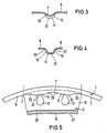
- the one-piece rim 1 with its rim flanges 4, the rim shoulders 5 and the rim base 6 is designed as a drop center rim, in the rim base 6 of which a circumferential bead 7 is incorporated, which has a flat V-shaped cross section is (Fig. 3).
- the bead 7, which is formed symmetrically to the radial plane, is offset from the radial center plane M of the rim by the track dimension on the rim base 6.
- the wheel bowl 2 is made as a four-lobed bowl, the four tabs 8 of which are arranged at the corners of the bowl, which is roughly square in outline. Accordingly, four lugs 3, each offset by 90 ° from one another, are provided for fastening the wheel disc 2 to the rim 1, which are designed as double lugs in the preferred exemplary embodiment.
- the wheel disc 2 is accordingly attached to each bracket 3 with the aid of two screws 10 which are offset with respect to one another in the circumferential direction of the rim.
- the rim base 6 has on the seat of the holding lugs 3 radially inwardly directed cam-like press-in 11, which are designed as local expressions of the surrounding bead 7 of the rim base and which, as shown primarily in Fig. 2, with a positive fit in the holding lugs 3 between their legs Border 12, the legs 12 in the opening area of the U-shaped holding blocks laterally against the flanks 13 of the cam-like pressings.
- the basic shape of the U-shaped bracket 3 with its two legs 12 and the profile web 14 connecting the legs 12 in one piece consist of sheet metal parts.
- the free ends of the legs 12 are provided with outwardly directed flanges 15, which lie on both sides next to the bead 7 and the cam-like press-in 11 against the rim base, on which the retaining lugs are firmly connected to the rim base 6 via weld seams 16 running in the circumferential direction of the rim .
- the legs 12 of the lugs 3 have aligned bolt holes 17 for the passage of the screws 10.
- the wheel bowl 2 is provided on its bowl tab 8 with two bolt holes 18 for the passage of the screws 10.
- the screw connections are secured by means of nuts 19 with washers 20 screwed onto the screws 10.
- the cam-like press-ins 11 provide local formations or depressions of the circumferential ones Bead 7 of the wheel rim 1. As shown in particular in FIGS. 2 and 4, the cam-like press-in operations 11 are symmetrical with the diameter plane of the rim 1 passing through the apex of the bead 7 with a bottom 21 convexly curved toward the wheel axis and towards the rim base 6 diverging flanks 13 formed, which end in the rim base 6 via curves 22. Fig.
- the rim 1 for each bracket 3 has two circumferentially offset cam-like impressions 11 which are formed from the circumferential bead 7 and the distance in the circumferential direction of the rim corresponds approximately to the distance between the bolt holes 17 on the bracket 3.
- the length of the cam-like press-in 11 in the rim circumferential direction is less than uie length of the bracket 3 in the rim circumferential direction.
- the cam-like impressions 11 run on their bottoms 21 from the area of the bolt holes 17 on both sides in a flat curve shape into the rim base 6, as shown at 23 in FIG. 5. From FIGS. 2 and 3 it can also be seen that the width of the cam-like impressions 11 is approximately equal to the width of the bead 7.
- the legs 12 of the lugs 3 nestle with their free end regions of the outer contour of the cam-like elevations 11, as a result of which a relatively large-area support of the legs 12 on the flanks 13 of the press-in portions 11 is achieved.
- the screw forces of the screws 10 used for fastening the bowl hold the legs 12 of the mounting blocks 3 in contact with the flanks 13 of the cam-like press-in 11.
- the arrangement can be such that the internal spacing of their two legs 12 is set during the production of the mounting blocks 3, that it is slightly smaller in the support area than the distance between the outer contact surfaces of the flanks 13. Accordingly, who which the bracket 3 pressed under a certain elastic deflection of their legs 12 from the inside on the press-in 11, whereby a surface prestress is achieved.
- the brackets 3 can then be fixed to the rim 1 with the aid of the weld seams 16.
- the weld seams 16 running in the circumferential direction of the rim 1 are not adversely loaded due to the support of the legs 12 on the flanks 13 under prestress by the axial screw forces. Due to the positive connection of the bracket 3 with the cam-like press-in 11 of the rim 1, the welds 16 are relieved of the axial wheel forces.
- the U-shaped brackets 3, measured between their legs 12, can have a width that is considerably smaller than their height. These dimensional ratios are preferably chosen when the tracking wheel or the like as a front wheel in a tractor. is used. With a narrow construction of the lugs 3, the cam-like press-in 11 can be formed with a correspondingly small width.
- the bracket 3 comprises in one piece the two end regions 25, which, measured over the profile web of the U-profile, extend over a length X, and the intermediate section 26 with the length Y. On the intermediate section 26, the profile web 14 of the U- Profile formed as a flat leg.
- the two profile legs 12 are substantially perpendicular to the profile web 14; they pass into the flat web with the inner radius of curvature Ry.
- the radius of curvature Ry is relatively small; it is generally about 4 to 7 mm.
- the outer surfaces of the profile webs 14 of the intermediate section 26 form flat contact surfaces for the wheel flaps 8.
- the U-profile is formed by the profile web 14 'and the two profile legs 12'.
- the profile web 14 'of the U-profile in the two end regions 25 of the bracket 3 is bulged towards the outside of the profile.
- the two profile legs 12 'in the curved transition region to the arched profile web 14' relative to the position of the profile legs 12 in the intermediate section 26 are drawn into the profile interior. This means that in the end regions 25 the profile legs 12 'with inner radii of curvature Rx into the profile web 14', which are considerably larger than the radii of curvature Ry in the intermediate section 26 of the bracket.
- the arrangement is such that the radius of curvature Rx increases continuously from the transition 27 (FIG. 6) to the intermediate section 26 in the direction of the adjacent end of the support bracket, as a result of which the kinking of the profile web shown in FIG. 6 in the end regions 25 of the Lugs result.
- the inner radius of curvature Rx is expediently considerably larger, preferably at least about 4 to 6 times larger than the radius of curvature Ry in the region of the intermediate section 26.
- the radius of curvature Rx can be at least approximately equal to half the inner profile width at the ends of the holding bracket.
- the center of curvature M lies in or near the vertical central axis A of the U-profile.
- the length X of the end regions 25 of the support bracket 3 formed in the above manner is advantageously approximately 10 to 20% of the total length of the support bracket, measured via its profile web 14, 14 '.
- the screw holes 17 for the screw bolts 10 are located outside the shaped end regions 25, that is to say in the region of the intermediate section 26 on the profile legs 12, in the vicinity of the transition points 27 to the end regions 25.
- the hole axes lie according to FIG. 7 approximately at the center M of the radii of curvature Rx.
- the wheel flaps 8 are supported only over a large area on the straight profile legs 12 in the intermediate section 26, where the screws 10 are also located.
- the transition regions 27 to the shaped end regions of the holding block 3 are indicated in FIG. 5 for the holding block according to FIG. 2.
- the bolt holes 17 are designed in the manner of an elongated hole or keyhole, since the screws 10 on their bolt heads 29 have cams 30 which serve to secure the rotation and which engage in the bolt holes (FIG. 2).
- the track width adjustment is carried out in a known manner in that the wheel disks 2 are connected in their one or other turning position either on the left or on the right profile leg 12 of the bracket 3 welded off-center to the rim.
Landscapes
- Engineering & Computer Science (AREA)
- Mechanical Engineering (AREA)
- Tires In General (AREA)
Applications Claiming Priority (2)
| Application Number | Priority Date | Filing Date | Title |
|---|---|---|---|
| DE3921121 | 1989-06-28 | ||
| DE3921121A DE3921121A1 (de) | 1989-06-28 | 1989-06-28 | Spurverstellrad |
Publications (1)
| Publication Number | Publication Date |
|---|---|
| EP0405100A1 true EP0405100A1 (fr) | 1991-01-02 |
Family
ID=6383740
Family Applications (1)
| Application Number | Title | Priority Date | Filing Date |
|---|---|---|---|
| EP90108767A Withdrawn EP0405100A1 (fr) | 1989-06-28 | 1990-05-10 | Roue à écartement réglable |
Country Status (5)
| Country | Link |
|---|---|
| US (1) | US5067776A (fr) |
| EP (1) | EP0405100A1 (fr) |
| BR (1) | BR9003020A (fr) |
| CA (1) | CA2016612A1 (fr) |
| DE (1) | DE3921121A1 (fr) |
Cited By (4)
| Publication number | Priority date | Publication date | Assignee | Title |
|---|---|---|---|---|
| EP0664227A1 (fr) * | 1994-01-25 | 1995-07-26 | GKN Sankey Limited | Roue |
| EP0684104A1 (fr) * | 1994-05-25 | 1995-11-29 | GKN Sankey Limited | Procédé pour la production d'un ensemble soudé |
| WO1997020704A1 (fr) * | 1995-12-06 | 1997-06-12 | Gkn Sankey Limited | Roues |
| GB2312880A (en) * | 1995-12-06 | 1997-11-12 | Gkn Sankey Ltd | Wheels |
Families Citing this family (5)
| Publication number | Priority date | Publication date | Assignee | Title |
|---|---|---|---|---|
| DE4123583C2 (de) * | 1991-07-12 | 1994-08-18 | Mannesmann Ag | Zweiteiliges Fahrzeugrad |
| IT250370Y1 (it) * | 2000-09-06 | 2003-09-10 | Titan Italia S P A | Ruota a carreggiata variabile con sistema di centraggio a spina |
| US7095342B1 (en) * | 2005-03-31 | 2006-08-22 | Intel Corporation | Compressing microcode |
| EP2607097B1 (fr) * | 2011-12-20 | 2015-11-11 | Titan Italia S.p.A. | Roue avec tracé ajustable |
| CN117734843B (zh) * | 2024-02-20 | 2024-04-30 | 成都理工大学 | 一种可调体型大小的越障机器人 |
Citations (5)
| Publication number | Priority date | Publication date | Assignee | Title |
|---|---|---|---|---|
| DE928868C (de) * | 1953-02-03 | 1955-06-13 | Paul Lemmerz | Scheibenrad fuer luftbereifte Fahrzeuge |
| DE1843932U (de) * | 1961-07-24 | 1961-12-21 | Suedrad G M B H Autoraederfabr | Fahrzeugrad mit mitteln zur spurverstellung. |
| US3117369A (en) * | 1959-06-06 | 1964-01-14 | Kronprinz Ag | Vehicle wheel |
| US4643484A (en) * | 1980-09-16 | 1987-02-17 | Karl Moeller Nagbol | Manually adjustable wheels |
| EP0319694A2 (fr) * | 1987-12-09 | 1989-06-14 | LEMMERZ-WERKE KGaA | Roue à voie réglable |
Family Cites Families (18)
| Publication number | Priority date | Publication date | Assignee | Title |
|---|---|---|---|---|
| US1582494A (en) * | 1921-04-02 | 1926-04-27 | James H Wagenhorst | Rim and felly |
| US2171170A (en) * | 1937-10-23 | 1939-08-29 | French & Hecht Inc | Wheel structure |
| FR871754A (fr) * | 1938-11-10 | 1942-05-09 | Roues, en particulier des roues à rayons pour des véhicules de tout genre, et procédé de fabrication de telles roues | |
| US2254361A (en) * | 1939-05-17 | 1941-09-02 | Allis Chalmers Mfg Co | Vehicle wheel |
| US2294256A (en) * | 1939-07-17 | 1942-08-25 | Cleveland Welding Co | Rim attaching device |
| US2476766A (en) * | 1945-07-30 | 1949-07-19 | Kelsey Hayes Wheel Co | Rim attaching means |
| US2474956A (en) * | 1947-06-18 | 1949-07-05 | Kelsey Hayes Wheel Co | Rim attaching means |
| GB666112A (en) * | 1948-12-22 | 1952-02-06 | Firestone Tire & Rubber Co | Improvements in or relating to wheel construction |
| DE837649C (de) * | 1950-09-28 | 1952-04-28 | Kronprinz Ag Fuer Metallindust | Fahrzeugrad, insbesondere fuer landwirtschaftliche Fahrzeuge |
| GB754725A (en) * | 1953-02-02 | 1956-08-15 | Paul Lemmerz | Disc wheel for vehicles having pneumatic tyres |
| FR1101487A (fr) * | 1953-11-20 | 1955-10-06 | Firestone Tire & Rubber Co | Forme de construction de roue |
| DE1048171B (de) * | 1956-01-16 | 1958-12-31 | Kronprinz Ag | Luftbereiftes Fahrzeugrad |
| DE1740693U (de) * | 1956-09-29 | 1957-02-28 | Lemmerz Werke Gmbh | Laufrad fuer fahrzeuge mit selbsttaetiger spurverstellung. |
| DE1238354B (de) * | 1961-07-19 | 1967-04-06 | Dayton Steel Foundry Co | Luftbereiftes Speichenrad mit abnehmbarer Ringfelge zur Aufnahme von Breitreifen |
| DE2247007C3 (de) * | 1972-09-25 | 1975-11-20 | Lemmerz-Werke Gmbh, 5330 Koenigswinter | Hohe Halteböckchen für die Befestigung von Spurverstellfelgen an den Radscheiben von Fahrzeugen, insbesondere Fahrzeugen für die Landwirtschaft |
| DE7605257U1 (de) * | 1976-02-21 | 1976-07-15 | Lemmerz-Werke Gmbh, 5330 Koenigswinter | Hohe halteboeckchen fuer die befestigung von spurverstellfelgen mit den radschluesseln von vorwiegend landwirtschaftlichen fahrzeugen |
| DE3069900D1 (en) * | 1979-09-18 | 1985-02-14 | Gkn Sankey Ltd | Wheels manually adjustable for varying track |
| DE3821533A1 (de) * | 1988-06-25 | 1989-12-28 | Lemmerz Werke Kgaa | Haltebock fuer spurverstellraeder |
-
1989
- 1989-06-28 DE DE3921121A patent/DE3921121A1/de not_active Withdrawn
-
1990
- 1990-05-10 EP EP90108767A patent/EP0405100A1/fr not_active Withdrawn
- 1990-05-11 CA CA002016612A patent/CA2016612A1/fr not_active Abandoned
- 1990-05-14 US US07/522,915 patent/US5067776A/en not_active Expired - Fee Related
- 1990-06-28 BR BR909003020A patent/BR9003020A/pt unknown
Patent Citations (5)
| Publication number | Priority date | Publication date | Assignee | Title |
|---|---|---|---|---|
| DE928868C (de) * | 1953-02-03 | 1955-06-13 | Paul Lemmerz | Scheibenrad fuer luftbereifte Fahrzeuge |
| US3117369A (en) * | 1959-06-06 | 1964-01-14 | Kronprinz Ag | Vehicle wheel |
| DE1843932U (de) * | 1961-07-24 | 1961-12-21 | Suedrad G M B H Autoraederfabr | Fahrzeugrad mit mitteln zur spurverstellung. |
| US4643484A (en) * | 1980-09-16 | 1987-02-17 | Karl Moeller Nagbol | Manually adjustable wheels |
| EP0319694A2 (fr) * | 1987-12-09 | 1989-06-14 | LEMMERZ-WERKE KGaA | Roue à voie réglable |
Cited By (7)
| Publication number | Priority date | Publication date | Assignee | Title |
|---|---|---|---|---|
| EP0664227A1 (fr) * | 1994-01-25 | 1995-07-26 | GKN Sankey Limited | Roue |
| US5560686A (en) * | 1994-01-25 | 1996-10-01 | Gkn Sankey Limited | Laterally movable wheel rim |
| EP0684104A1 (fr) * | 1994-05-25 | 1995-11-29 | GKN Sankey Limited | Procédé pour la production d'un ensemble soudé |
| WO1997020704A1 (fr) * | 1995-12-06 | 1997-06-12 | Gkn Sankey Limited | Roues |
| GB2312880A (en) * | 1995-12-06 | 1997-11-12 | Gkn Sankey Ltd | Wheels |
| GB2312880B (en) * | 1995-12-06 | 1999-05-12 | Gkn Sankey Ltd | Wheels |
| US5938291A (en) * | 1995-12-06 | 1999-08-17 | Gkn Sankey Limited | Wheels |
Also Published As
| Publication number | Publication date |
|---|---|
| DE3921121A1 (de) | 1991-01-03 |
| US5067776A (en) | 1991-11-26 |
| BR9003020A (pt) | 1991-08-20 |
| CA2016612A1 (fr) | 1990-12-28 |
Similar Documents
| Publication | Publication Date | Title |
|---|---|---|
| DE112008002810B4 (de) | Rad für ein Fahrzeug | |
| DE112006000508T5 (de) | Radscheibe für ein zusammengesetztes Kraftfahrzeugrad sowie zusammengesetztes Kraftfahrzeugrad mit einer solchen Radscheibe | |
| WO2007051453A2 (fr) | Moyeu de roue pourvu d'evidements axiaux formes entre les trous destines a des boulons de roue | |
| EP1951530B1 (fr) | Roue de véhicule et son procédé de fabrication | |
| DE19807943C2 (de) | Rad für ein Fahrzeug, insbesondere Ersatzrad für ein Kraftfahrzeug | |
| DE2137595A1 (de) | Achsenspindel und Verfahren zu ihrer Herstellung | |
| EP0807025B1 (fr) | Roue de vehicule et procede pour sa fabrication | |
| DE202012104260U1 (de) | Fahrzeugrad für Personenkraftwagen | |
| EP0405100A1 (fr) | Roue à écartement réglable | |
| EP1626875B1 (fr) | Roue de vehicule en tole, notamment en tole d'acier | |
| DE3700422C2 (fr) | ||
| EP0319694B1 (fr) | Roue à voie réglable | |
| EP0348613B1 (fr) | Support de fixation pour roues à écartement réglable | |
| EP0522672B1 (fr) | Roue de véhicule en deux pièces | |
| DE2660404C2 (de) | Befestigungsanordnung zur Montage einer Reifenfelge an Radkranzteilen | |
| DE3541123C2 (fr) | ||
| DE102009011378A1 (de) | Türaufprallträger | |
| EP3449148B1 (fr) | Disque de frein pour un véhicule | |
| EP0062271A1 (fr) | Dispositif de fixation | |
| EP3702180B1 (fr) | Châssis pour un véhicule utilitaire, coques associées ainsi qu'agencement de deux coques formant une paire de coques associé | |
| EP1404534B1 (fr) | Roue arriere de bicyclette | |
| DE19836239C2 (de) | Fahrzeugrad | |
| DE4225903C2 (de) | Radadapter für Lastfahrzeugräder | |
| EP3094497B1 (fr) | Jante de roue à rayons | |
| DE2512029C3 (de) | Fahrzeugrad mit axial verstellbarer Felge |
Legal Events
| Date | Code | Title | Description |
|---|---|---|---|
| PUAI | Public reference made under article 153(3) epc to a published international application that has entered the european phase |
Free format text: ORIGINAL CODE: 0009012 |
|
| AK | Designated contracting states |
Kind code of ref document: A1 Designated state(s): AT DE DK ES FR GB IT |
|
| 17P | Request for examination filed |
Effective date: 19910411 |
|
| 17Q | First examination report despatched |
Effective date: 19930126 |
|
| STAA | Information on the status of an ep patent application or granted ep patent |
Free format text: STATUS: THE APPLICATION HAS BEEN WITHDRAWN |
|
| 18W | Application withdrawn |
Withdrawal date: 19930602 |