EP0404041B1 - Caisse repliable pour maintenir des emballages - Google Patents
Caisse repliable pour maintenir des emballages Download PDFInfo
- Publication number
- EP0404041B1 EP0404041B1 EP90111518A EP90111518A EP0404041B1 EP 0404041 B1 EP0404041 B1 EP 0404041B1 EP 90111518 A EP90111518 A EP 90111518A EP 90111518 A EP90111518 A EP 90111518A EP 0404041 B1 EP0404041 B1 EP 0404041B1
- Authority
- EP
- European Patent Office
- Prior art keywords
- side walls
- crate
- side wall
- crates
- hinge
- Prior art date
- Legal status (The legal status is an assumption and is not a legal conclusion. Google has not performed a legal analysis and makes no representation as to the accuracy of the status listed.)
- Expired - Lifetime
Links
Images


Classifications
-
- B—PERFORMING OPERATIONS; TRANSPORTING
- B65—CONVEYING; PACKING; STORING; HANDLING THIN OR FILAMENTARY MATERIAL
- B65D—CONTAINERS FOR STORAGE OR TRANSPORT OF ARTICLES OR MATERIALS, e.g. BAGS, BARRELS, BOTTLES, BOXES, CANS, CARTONS, CRATES, DRUMS, JARS, TANKS, HOPPERS, FORWARDING CONTAINERS; ACCESSORIES, CLOSURES, OR FITTINGS THEREFOR; PACKAGING ELEMENTS; PACKAGES
- B65D11/00—Containers having bodies formed by interconnecting or uniting two or more rigid, or substantially rigid, components made wholly or mainly of plastics material
- B65D11/18—Containers having bodies formed by interconnecting or uniting two or more rigid, or substantially rigid, components made wholly or mainly of plastics material collapsible, i.e. with walls hinged together or detachably connected
- B65D11/1833—Containers having bodies formed by interconnecting or uniting two or more rigid, or substantially rigid, components made wholly or mainly of plastics material collapsible, i.e. with walls hinged together or detachably connected whereby all side walls are hingedly connected to the base panel
Definitions
- the present invention relates to a folding crate for holding packages according to the preamble of claim 1 (FR-A-578 587). More particularly, the present invention relates to a foldable crate for holding gable-top type packages.
- packages that contain various products such as, for example, liquids
- the crates are dimensioned to receive and hold a plurality of packages. In that way, numerous packages can be more easily shipped at the same time.
- the crates in which the packages are to be placed are usually manufactured as a one piece rigid unit.
- that type of construction presents several drawbacks.
- a second disadvantage associated with crates that possess a rigid construction is that after the packages have been removed from the crates, the empty crates must be transported back to the distributor or to the packaging plant. Once again, since the size of the crates cannot be reduced, a large amount of space is required to transport the empty crates. As mentioned, that waste of space is not very cost efficient.
- U.S. -A- 3,841,477 addresses the aforementioned problems. That patent discloses an outer container for holding a plurality of packages in a close, tightly packed arrangement for transport or the like.
- the container is manufactured from a piece of rigid plastic material and includes a base portion and two sides that are connected to the base portion by hinge members. When packages are located in the container, the sides are positioned upright so that the sides and the base portion form a U-shaped member.
- a strap encircles the container and the packages located in the container.
- the hinges that connect the sides to the base member permit the sides to be folded outward so that when the container is not being used to hold packages, the container can be unfolded to a flat configuration.
- the container is susceptible to certain improvements.
- the construction of the container is such that when packages are positioned in the container, the containers cannot be stacked on top of one another in a stable manner because the tops of the packages extend above the edges of the sides of the container.
- the containers rest on the upper surfaces of the packages positioned in the underlying container.
- the containers are able to slide relative to the underlying containers.
- the inability of the containers to be stacked on top of one another in a stable manner becomes an even greater problem when packages having non-planar tops, for example, gable-top type packages are positioned in the containers.
- the aforementioned container also suffers from certain drawbacks with respect to the manner in which the container is folded. Although the aforementioned container is capable of being unfolded in a flat condition, the sides of the container are not adapted to be folded inwardly. Thus, that container is not capable of being folded into a more compact form.
- the container cannot be readily stacked on top of another container and aligned therewith to form a stable stack of flat folded containers.
- the aforementioned container also is not designed to carry loads such as those produced when packages are placed in the container and the package-filler container is stacked on top of another package-filled container.
- the containers are designed so that the packages in the container extend above the top edges of the sides of the container.
- the load produced by the stacked containers must be supported by the packages and the packages may not be designed to support such loads.
- French Patent No. FR-A-578,587 discloses a folding shipping box that has four folding sides.
- the folding arrangement allows the sides to fold inward with one side wall on another to provide a compact arrangement.
- a disadvantage of this shipping box is that the side walls are able to swing outwardly, so that it is necessary for the side walls to be connected together at each corner by hooks. Further, the box is difficult to erect.
- Another object of the present invention is to provide a foldable crate that permits the crate to be easily aligned and stacked when the crate is filled with packages in order to result in a stable stack of crates.
- a further object of the present invention is to provide a foldable crate that is constructed so as to permit the folded crate to be easily stacked and aligned on top of another crate in order to result in a stable stack of folded crates.
- An additional object of the present invention is to provide a foldable crate that is adapted to support the loads produced by the stacking of package-filled crates.
- Another object of the present invention is to provide a folding crate that can accommodate gable-top type packages, while permitting the crates to be stably stacked on, top of one another.
- the folding crate in accordance with the present invention includes a bottom member having a planar support surface upon which a plurality of packages are adapted to be placed, a first side wall and a second side wall.
- a first hinge arrangement hingedly connects the first side wall to the bottom member for permitting the first side wall to be folded toward the bottom member about a hinge axis.
- a second hinge arrangement hingedly connects the second side wall to the bottom member for permitting the second side wall to be folded toward the bottom member about a hinge axis.
- the hinge axis about which the first hinge arrangement pivots is parallel to the hinge axis of the second hinge arrangement and the hinge axis of the first hinge arrangement is spaced from the support surface a greater distance than the hinge axis of the second hinge arrangement.
- Another feature of the invention are at least two projections on the bottom member which are in position to engage in corresponding sockets in the underside of another crate to facilitate stacking the crates when the side walls are placed over the support surface.
- an arrangement that forms a part of the bottom member and the first side wall is provided for inhibiting the first side wall from being folded outwardly beyond a substantially vertical position with respect to the bottom.
- An arrangement that forms a part of the bottom member and the second side wall is also provided for inhibiting the first side wall from being folded outwardly beyond a substantially vertical position with respect to the bottom.
- the bottom member includes slots extending along the bottom and aligned with the hinge pins and the side walls have edge portions shaped to correspond to the slots.
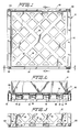
- the folding crate 60 includes, as seen in FIGS. 1-16, a bottom member 62, a first side wall 64 and a second side wall 66.
- the bottom member 62 is manufactured to have a plurality of openings 68 that extend therethrough in order to make the bottom member 62 lighter in weight and cheaper to manufacture as a result of reduced material costs.
- the bottom member 62 has a planar support surface 63 upon which a plurality of packages are to be placed.
- the first side wall 64 has a first end 70 and a second end 72.
- the second side wall 66 has a first end 74 and a second end 76.
- Each of the first and second side walls 64, 66 has a ribbed outer surface and a planar inner surface.
- the planar inner surface permits the packages that are positioned inside the crate 60 to be placed flush up against the inner surface of the first and second side walls 64, 66.
- the ribbed outer surface of each of the side walls 64, 66 results in light weight construction and reduced material costs.
- the first side wall 64 has a handle opening 78 that extends completely therethrough adjacent the first end 70.
- the second side wall 66 has a handle opening 80 that extends completely therethrough adjacent the first end 74.
- the handle openings 78, 80 are positioned at substantially the same distance from the respective first ends 70, 74 so that the handle openings 78, 80 are in substantial horizontal alignment.
- the handle openings 78, 80 serve as handles for lifting the crate when the side walls 64, 66 are positioned vertically upright.
- the first side wall 64 is connected to the bottom 62 by way of a first hinge arrangement 82 while the second side wall 66 is connected to the bottom 62 by way of a second hinge arrangement 84.
- first hinge arrangement 82 the first hinge arrangement
- second hinge arrangement 84 the details of the first and second hinge arrangements 82, 84 will be described.
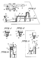
- the first hinge arrangement 82 includes a plurality of knuckles 86 that extend from the second end 72 of the first side wall 64. Each of the knuckles 82 has a longitudinally extending hole 88 that defines a hollow knuckle. The features of the first hinge means 82 are shown more clearly in the exploded view of FIG. 8. In FIG. 8, one of the knuckles 86 and the hole 88 that extends longitudinally therethrough are clearly shown.
- the first hinge means 82 further includes a plurality of spaced apart openings 90 positioned along one side of the bottom 62.
- the arrangement of the spaced apart openings 90 can be more clearly seen in FIG. 3.
- the openings 90 are spaced apart the same distance that the knuckles 86 are spaced apart. In that way, each one of the knuckles 86 can be fitted into one of the openings 90.
- the first hinge arrangement 82 further includes a longitudinal hole 92 that extends along a substantial portion of a length of one side of the bottom 62. Additionally, the first hinge arrangement 82 includes a pin 94 that extends through the longitudinally extending hole 92 in the side of the bottom and through the openings 88 in the knuckles 86 that extend from the second end 72 of the first side wall 64.
- the longitudinally extending hole 92 is open to the exterior of the crate at one side face of the crate, as seen in FIG. 8, so that the pin 94 can be properly inserted through the longitudinally extending hole 92 and through the holes 88 in the knuckles 86 after the knuckles 86 have been positioned in openings 90.
- the longitudinally extending hole 92 does not extend completely through the side of the bottom 62. Rather, the longitudinally extending hole 92 extends only so far as to permit the pin 94 to be inserted through the aligned openings 88, 92 and abut against the wall 96. In that way, the pin 94 is completely housed within the side of the crate.
- the holes 88 extend through the knuckles 86 open to the inner side of the first side wall 64 by way of the slotted opening 96. Similarly, the longitudinally extending hole 88 opens to the outer side of the first side wall 64 through two slotted openings 98.
- the first side wall 64 is inserted into the bottom 62 by first aligning each one of the knuckles 86 with one of the openings 90 in the side of the bottom 62.
- the first side wall 64 is then lowered toward the bottom 62 so that the knuckles 86 are positioned in the openings 90 and so that the longitudinally extending openings 88 in the knuckles 86 are in alignment with the longitudinally extending opening 92 in the side of the bottom 62.
- the pin 94 as seen in FIG. 8, is then inserted through the aligned openings 88 and 92.
- the second side wall 66 is substantially identical to the first side wall 64 and thus, detailed drawings of the second side wall and the knuckles that extend therefrom are not included.
- a second side wall 66 is shown after it has been inserted into the bottom 62.
- Knuckles 87 extending from the second end 76 of the second side wall 66 are positioned in openings 91 in a side of the bottom 62 that is positioned opposite to the side to which the first side wall 64 is hingedly connected.
- Holes 89 that extend longitudinally through the knuckles 87 are aligned with a longitudinally extending hole 93 that extends through the opposite side of the bottom 62.
- a pin 95 is positioned so that it passes through the aligned holes 89 in the knuckles 87 and the longitudinally extending hole 93 in the opposite side of the bottom 62.
- the above-described construction of the bottom 62 and the first and second side walls 64, 66 and the manner in which the first and second side walls 64, 66 are connected to the bottom 62 is advantageous because it permits the first and second side walls 64, 66 to be folded inwardly in order to produce a compact folded crate when the crate is not in use.
- the first side wall 64 and the second side wall 66 can be positioned in a substantially vertical position for receiving packages. After the packages have been removed the second side wall 66 can be folded inwardly as shown in phantom in FIG. 4 in the direction of arrow B.
- the first side wall 64 can be folded inwardly in the direction of arrow A as shown in phantom in FIG. 4.
- the resulting folded configuration of the crate is depicted in FIG. 5.
- the first and second hinge arrangements 82, 84 are positioned such that in the folded configuration, the first and second side walls 64, 66 can lie substantially horizontal and can be positioned substantially parallel to each other and to the support surface 63 as illustrated in FIG. 5.
- the first and second side walls 64, 66 are capable of being positioned in that manner when folded because the hinge axis about which the first side wall 64 pivots or folds is at an elevationally different position than the hinge axis about which the second side wall 66 pivots or folds.
- the hinge axis of the first hinge arrangement 82 lies in a plane parallel to the planar support surface 63 that is spaced from the plane parallel to the planar support surface 63 in which the hinge axis of the second hinge arrangement 84 lies.
- the vertical distance between the hinge axes about which the first and second side walls 64, 66 pivot or fold as measured in a direction perpendicular to the planar support surface 63 is approximately equal to the thickness of the first side wall 64.
- each of the side walls 64, 66 has an end face from which the knuckles extend.
- the knuckle 86 is shown as extending from an end face 102.
- the bottom 62 has an upstanding wall 104 that extends upwardly beyond the planar support surface 63.
- the upstanding wall 104 also has an upper surface 106.
- the first side wall 64 When the first side wall 64 is inserted into the bottom 62 so that the knuckles 86 are positioned in the openings 90, the end face 102 of the first side wall 64 contacts and rests against the upper surface 106 of the upstanding wall 104.
- FIG. 12 which shows the second side wall 66 hingedly connected to the bottom 62, the upper surface 108 of the upstanding wall 110 and the end face 112 of the second side wall 66 abut against one another. Because the end faces 102, 112 of the first and second side walls 64, 66 rest against the upper surfaces 106, 108 of the upstanding walls 104, 110, the first and second side walls 64, 66 cannot fold outwardly away from each other.
- construction of the crate does permit the first and second side walls 64, 66 to fold slightly outwardly beyond the vertical position. That slight outward movement permits a loading assembly to be inserted between the first and second side walls 64, 66 in order to urge the first and second side walls 64, 66 outwardly beyond the vertical position prior to placing the packages in the crate.
- the ability of the loading assembly to urge the first and second side walls 64, 66 outwardly prior to inserting the packages into the crate permits the packages to be more easily inserted into the crate.
- the crate be constructed such that the first and second side walls 64, 66 are able to move slightly outwardly beyond the vertically upright position before the end faces 102, 112 of the first and second side walls 64, 66 come in contact with and rest against the upper surfaces 104, 108 of the upstanding walls 104, 110.
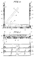
- FIG. 13 Another function associated with the construction of the side walls 64, 66 and the bottom 62 as described above is that such construction helps support the load that develops when the crates are filled with packages and are then stacked on top of one another.
- FIG. 13 two crates 60 are shown in a stacked configuration. It is readily apparent that when packages 200 are placed in the crates 60, the weight of the crates 60 is significantly increased. Depending upon the contents of the crates, the increase in weight can be quite significant.
- the load i.e., the weight of the crates and the packages
- the contact that occurs between the end faces 102, 112 of the first and second side walls 64, 66 and the upper surfaces 106, 108 of the upstanding walls 104, 110 helps distribute the load which is transmitted through the first and second side walls 64, 66. Further, the upper surfaces 106, 108 of the upstanding side walls 104, 110 serve to support a portion of the load produced by stacking package-filled crates.
- the load i.e., the weight of the crates and the packages
- the load that is transmitted through the first and second side walls 64, 66 is also distributed to other areas of the bottom 62 as a result of the manner in which the pins 94, 95 are arranged with respect to the bottom 62.
- FIG. 8 it can be seen that, in the case of the first side wall 64, once the first side wall 64 is positioned on the bottom 62 so that the knuckles 86 extend through the openings 90 to the side of the bottom and the pin 94 is properly inserted through the aligned longitudinally extending hole 92 and the holes 88 in the knuckles 86, the pin 94 will rest on surfaces 14.
- the knuckles 86 will rest on and be supported by the pin 84. Consequently, the load that is transmitted through the first and second side walls 64, 66 will be distributed to the sides of the bottom through the surfaces 114 upon which the pins 84 rest. It is, of course, understood that the second side wall 66 and pin 95 arrangement are configured in substantially the same manner as that noted above and thus, that arrangement also serves to transmit and distribute the load produced by stacked crates that contain packages.
- Another advantage associated with the folding crate according to the first embodiment of the present invention is that an arrangement is provided on the folding crate to facilitate stacking of the crates and orientation of the crates with respect to one another when the crates are in the folded configuration.
- That arrangement includes, as seen in FIG. 5, a plurality of projections 100 that extend upwardly from the sides of the bottom 62.
- a plurality of projections 100 that extend upwardly from the sides of the bottom 62.
- at least two and preferably four projections are provided, each of which extends upwardly from one of the corners of the bottom 62.
- the projections 100 are configured such that when the first and second side walls 64, 66 are folded inwardly and positioned substantially horizontally as illustrated in FIG. 5, the projections 100 extend upwardly a sufficient distance above the outer surface of the first side wall 64.
- the bottom 62 of the crate also includes hollow portions 116 at the underside of the corners of the crate.
- the projections 100 and the hollow underside portions 116 of the crate permit the crates to be easily stacked on top of one another and oriented with respect to one another when the first and second side walls 64, 66 are folded inwardly.
- the projections 100 are set inwardly from the outer side face of the bottom 62 so that the projections 100 on one crate can fit into the hollow underside portions 116 of a crate positioned thereabove.
- the presence of the projections 100 permits the crates to be accurately aligned with respect to one another during stacking so as to produce a stack of crates that is stable.
- the projections 100 are preferably located at the corners of the bottom 62, it can be readily seen that accurate alignment of the stacked crates can also be achieved if the projections 100 are positioned at places other than the corners of the bottom 62.
- the crates may not be readily separable from one another when they are in the stacked condition illustrated in FIG. 5.
- the bottom 62 of the crate is provided with a hole 150 as seen in FIG. 6.
- another substantially identical hole (not shown) is provided on the opposite side of the bottom 62.
- the holes 150 are located in the outer faces of the sides of the bottom 62 and each of the holes 150 opens to the underside surface of the bottom 62.
- Each of the holes 150 is adapted to receive a pin that is preferably positioned in the holes 150 after the crates have been stacked.
- the pin permits the crates to be more easily separated by allowing a downward force to be directed against the bottom most crate while the remaining crates in the stack are lifted upward. That is, a machine can be employed to grab the pins located between the bottom two crates in order to apply a downward force against the bottom most crate while the other crates in the stack are being pulled upwardly.
- a cut-out portion 118 is positioned in an outer side face of the bottom 62.
- another cut-out portion is located in the outer side face of the bottom 62 located opposite to the cut-out 118 shown in FIG. 7.
- the cut-out portions 118 are located on those sides of the bottom 62 where the holes 150 are not located.
- the cut-out portions 118 open to the underside of the bottom 62.
- the cut-out portions 118 are configured in such a manner as to permit a dragging hook to be positioned therein for facilitating movement of a stack of crates across a floor.
- a dragging hook can be positioned in one of the cut-out portions 118 so as to permit the entire stack of crates to be dragged across the floor.
- the underside surface 120 of the bottom 62 includes inclined portions 122.
- the inclined portions 122 of the underside surface 120 extend along opposite sides of the bottom 62.
- the inclined portions 122 of the underside surface 120 are positioned opposite to the cut-out portions 118.
- cut-out portion 118 would be positioned in outer side face surface 124 as seen in FIG. 6 while another cut-out portion would be positioned in outer side face surface 126 of the bottom 62.
- the inclined portions 122 facilitate movement of the crates when a stack of crates is dragged across the floor because the lower edges of the bottom 62 of the crate are raised off the surface of the floor.
- the bottom crate in a stack of crates can move across the floor surface much more readily and with less chance of becoming impeded in its movement.
- the outer face of the first side wall includes at least one and preferably at least two grooves 128 that extend across the entire width thereof.
- the second side wall 66 includes at least one and preferably at least two grooves 130 in the outer face thereof that extend across substantially the entire width of the second side wall 66.
- Each of the grooves 128 in the first side wall 64 are horizontally aligned with one of the grooves 130 in the second side wall 66.
- Straps 132 are positioned in the aligned grooves 128, 130 in the first and second side walls 64, 66. The straps 132 encircle the crate 60 when packages 200 are positioned in the crate 60 so that the packages 200 are securely held in place in the crate 60 and are prevented from falling out of the crate 60.
- the first embodiment of the folding crate 60 is configured such that when packages 200 are positioned in the crate 60, the crates can be stacked on top of one another.
- underside portions 134 of the bottom 62 that are positioned below the hinge connections are hollow.
- the hollow underside portions 134 extend along the portion of the sides of the bottom 62 to which the first and second side walls 64, 66 are hingedly connected.
- the hollow underside portions 134 are adapted to receive the upper ends of the first and second side walls 64, 66. As can be seen from FIG.
- the first and second side walls 64, 66 when one crate 60 is stacked on top of another crate, the first and second side walls 64, 66 must be bent slightly inwardly in the direction of arrows C so that the upper ends of the first and second side walls 64, 66 can be seated in the hollow underside portions 134.
- the upper ends of the first and second side walls 64, 66 could be narrowed in thickness so that the upper ends 64, 66 of the first and second side walls 64, 66 can be seated in the hollow underside portions without bending the side walls 64, 66 inwardly.
- the upper ends of the first and second side walls 64, 66 are preferably beveled so that the side walls 64, 66 can be more easily inserted into the hollow underside portions 134.
- the upper ends of the first and second side walls 64, 66 i.e., the ends farthest from the bottom 22
- the length of the first side wall 64 is shorter than the length of the second side wall 66. That difference in length between the first and second side walls 64, 66 takes into account the fact that the hinge axis about which the first side wall 64 pivots is positioned at a vertically higher position than the hinge axis about which the second side wall 66 pivots.
- the difference in length between the first and second side walls 64, 66 is substantially equal to the vertical distance between the hinge axis about which the first side wall 64 pivots and the hinge axis about which the second side wall 66 pivots.
- a folding crate 360 includes a bottom member 362, a first side wall 364 and a second side wall 366.
- the bottom member 362 is formed to have a plurality of openings 368 that extend therethrough in order to make the bottom member 362 lighter in weight and less expensive to manufacture as a result of reduced material.
- the bottom member 362 has a planar support surface 363 upon which a plurality of packages are to be placed.
- the bottom member 362 of the second embodiment also includes at least four reinforcement ribs 302 extending between the first and second side walls 364, 366 to provide added strength to the bottom member 362. Partial ribs 333 extending only a portion of the distance between the side walls may also be included to provide strength to the bottom member 362.
- the first side wall 364 has a first end 370 and a second end 372. Along the edge of the first end 370 of the first side wall 364 are disposed at least four finger protrusions 303.
- the second side wall 366 has a first end 374 and a second end 376, and positioned along the edge of the second end 376 are finger protrusions 304.
- the finger protrusions 303, 304 of each side wall 364, 366 aid the stacking capability of the crate of the second embodiment.
- each of the first and second side walls 364, 366 has a ribbed outer surface and a planar inner surface.
- the side walls 364, 366 of the second embodiment have more ribs than the side walls 64, 66 of the first embodiment in order to ensure sufficient strength and stability to each of the side walls.
- the planar inner surface of each of the side walls permits packages 200 that are positioned inside the crate 360 to be positioned flush against the inner surface of the first and second side walls 364, 366.
- the first side wall 364 has a handle opening 378 that extends completely therethrough and is located near the first end 370 of the side wall 364.
- the second side wall 366 similarly has a handle opening (not shown) that extends completely therethrough and that is located near the first end 374 of the side wall 366.
- the handle openings on each of the sidewalls are positioned at substantially the same distance from the respective first ends 370, 374 so that the handle openings are in substantial horizontal alignment. The handle openings are useful for lifting the crate when the side walls 364, 366 are positioned vertically upright.
- the first side wall 364 is connected to the bottom 362 at a first hinge arrangement 382, while the second side wall 366 is connected to the bottom 362 at a second hinge arrangement 384.
- the first and second hinge arrangements 382, 384 are substantially the same as the first and second hinge arrangements 82, 84, respectively, of the first embodiment of the present invention.
- the first and second side walls 364, 366 of the second embodiment may be folded inwardly in order to produce a compact, folded crate when the crate is not in use as shown in FIG. 18.
- the first and second hinge arrangements 382, 384 are positioned such that, in the folded configuration, the first and second side walls 364, 366 are positioned substantially horizontal and can be positioned substantially parallel to each other and to the support surface 363 as illustrated in FIGS. 18 and 23.
- the first and second side walls 364, 366 are capable of being positioned in such a manner because the hinge axis about which the first side wall 364 pivots is at an elevationally different position than the hinge axis about which the second side wall 366 pivots. That is, the hinge axis of the first hinge arrangement 382 lies in a plane parallel to the planar support surface 363 and is spaced apart from the plane parallel to the planar support surface 363 in which the hinge axis of the second hinge arrangement 384 lies.
- the vertical distance between the hinge axes about which the first and second side walls 364, 366 pivot is approximately equal to the thickness of the first side wall 364 as measured in a direction perpendicular to the planar support surface 363.
- each of the side walls 364, 366 includes a gusset 310, 312, positioned at a lower end of each side wall 364, 366, respectively, that restricts additional pivoting movement of each side wall 364, 366.
- the gusset 310 of the second side wall 366 as shown in FIG. 17 is comprised of a series of ribs 341 extending upward from a planar land 342 and intersecting with the outside surface of the second side wall 366. Since ribs 341 extend upward and into the outside surface of the second side wall 364, the gusset 312 takes on a substantially triangular shape as viewed from the side as in FIGS. 15 and 18-20.
- the planar land 342 is disposed along the entire edge of the second side wall 366 at the second end 372 and extends perpendicularly therefrom.
- the planar land 342 of the gusset 310 includes a planar abutment surface 11 such that when the second side wall 366 has been pivoted to a vertical position, the abutment surface 311 of the gusset 310 abuts against a mating planar surface 314 of the bottom 362 as shown in FIG. 19.
- the two planar surfaces 311, 314 abut against one another, the second side wall 366 is thus inhibited from further pivoting movement and is thus maintained in a substantially vertical position.
- the gusset 312 of the first side wall 366 is substantially identical to the gusset 310 of the second side wall 366. That is, the gusset 310 is comprised of a series of ribs 345 extending upward from a planar land 346 and intersecting with the outer surface of the first side wall 364. Since the ribs 345 extend upward and into the outside surface of the first wall 364, the gusset 310 takes on a triangular shape as viewed from the side as shown in FIGS. 15 and 18-20.
- the planar land 346 is disposed along the entire edge of the first side wall 364 and extends perpendicularly therefrom.
- the planar land 346 includes a planar abutment surface 313 such that when the second side wall has been pivoted to a vertical position, the abutment surface 313 is abutted with a mating planar surface 316 of the bottom 362 to thus prevent further pivoting movement of the second side wall 366. In this manner, both the first and second side walls 364, 366 are inhibited from being folded outwardly beyond a substantially vertical position relative to the bottom 362.
- the side walls 364, 366 and the bottom 362 of the second embodiment are configured to support the load that develops when each crate is filled with packages and then the crates are stacked on top of one another.
- the second embodiment of the present invention is configured to further facilitate proper weight distribution and to further ensure proper crate strength.
- the bottom 362 is configured to have a plurality of vertical ribs 347 disposed along the side of the bottom 362 that extend from the second hinge arrangement 384 to a bottom surface of the bottom 362.
- the ribs form at least four slots 320 that are configured to receive a corresponding finger protrusion 304 of one of the side walls when crates are loaded and stacked upon each other. More specifically, when a plurality of loaded crates are stacked on top of one another, the finger protrusions 303 of each side wall 364, 366 in an underlying crate are received in a corresponding slot 320 of the bottom 362 when the crates are stacked upon one another. The ribs 347 then come into contact with the top edges of the side walls 364, 366 in the area between each finger protrusion 303 and are thus supported thereby. In this manner, adequate weight distribution and crate support is provided.
- the second embodiment of the present invention includes a plurality of projections 100 that are received in corresponding hollow receptacles 340 of the above stacked crate in order to facilitate the stacking of the crates when the crates are oriented in a folded configuration.
- at least one of the hollow receptacles 340 located on the underside of the bottom 362 at the corners of the crate includes a post 341 extending substantially the height of the receptacle 340.
- at least one of the corners on the top side of the bottom 362 does not have a protrusion 100. Consequently, during stacking of folded crates of the second embodiment, as shown in FIG.
- the hollow receptacle 340 of the above stacked crate not having a protrusion 100 must be situated beneath the hollow receptacle 340 of the above stacked crate having the post 341. If an operator attempts to stack the crate such that a corner having a protrusion 100 is positioned beneath the hollow receptacle 340 of the above stacked crate having the post 341, the protrusion 100 will be prevented from being received by the hollow receptacle 340 due to the post 341 and the operator will be forced to re-orient the crate for correct stacking. In this manner, the alignment of each crate within a stack is maintained.
- the second embodiment includes a cut-out portion 118 for which a dragging hook can be positioned so as to permit an entire stack of crates to be dragged across the floor.
- the second embodiment includes inclined portions 122 on the underside surface of the bottom 362 to facilitate the moving of the stack of crates across the floor surface.
- the outer faces of the side walls in the second embodiment also include at least two grooves 128 that extend across the entire width thereof for receiving straps 132 which secure the packages 200 within the crate.
- first side wall 364 is shorter than the length of the second side wall 366 so as to permit the crates to be stacked on top of one another in a level and stable manner.
- hinge axes of both the first and second hinge arrangements 382, 384 could be positioned at the same height, thus enabling the length of the first and second side walls 364, 366 to be equal.
- the axes of the first and second hinge arrangements must be positioned at a suitable height above the planar surface 363 of the bottom 362 to allow sufficient room for folding the two equal height side walls.
- first and second hinge arrangements 382, 384 must provide sufficient depth relative to the planar surface 363 so that the first and second side walls 364, 366 may be folded inwardly such that the protrusions 100 extend above the first and second side walls in the folded condition.
- the crates 60, 360 are adapted to receive any type of packages.
- the first and second embodiments are especially well suited to receive gable-top type packages 200.
- the crate 60 and the crate 360 are preferably constructed such that the uppermost strap 132 is positioned below the top of the gable-top type packages 200.
- the handle openings in the first and second side walls, respectively are positioned at or above the level of the gable-top type portion of the packages 200 so that an individual can place his hands through the handle openings without interference from the packages 200.
- the folding crates according to the first and second embodiments of the present invention are preferably manufactured from polypropylene, although other types of material such as polyphenylene-oxide and polycarbonate could be employed.
Landscapes
- Engineering & Computer Science (AREA)
- Mechanical Engineering (AREA)
- Rigid Containers With Two Or More Constituent Elements (AREA)
- Supplying Of Containers To The Packaging Station (AREA)
- Basic Packing Technique (AREA)
- Control And Other Processes For Unpacking Of Materials (AREA)
- Auxiliary Devices For And Details Of Packaging Control (AREA)
Claims (4)
- Caisse repliable pour le maintien d'emballages comprenant : un organe de fond rectangulaire (62, 362) ayant une surface support sensiblement plane (63, 363) supportant les emballages ; une paire de parois latérales (64, 66, 364, 366) fixées le long des côtés opposés de l'organe de fond (62, 362) par le moyen d'une disposition articulée (82, 84, 382, 384) qui permet aux parois latérales (64, 66, 364, 366) de pivoter en direction de la surface support (63, 363), la disposition articulée (82, 84, 382, 384) comprend des goupilles d'articulation (94, 95) dans l'organe de fond (62, 362) et les parois latérales (64, 66, 364, 366) et comprend des éléments d'articulation coopérant avec les goupilles, les goupilles d'articulation dans l'une des parois latérales (64, 364) étant espacées d'une plus grande distance au-dessus de la surface (63, 363) que la goupille d'articulation sur l'autre paroi latérale (66, 366) de façon à permettre à l'autre paroi latérale (66, 366) d'être placée sur la surface support (63, 363) et ladite première paroi latérale (64, 364) d'être placée sur l'autre paroi latérale (66, 366) de façon à constituer une disposition compacte, ladite caisse étant caractérisée en ce que l'organe de fond (62, 362) comporte au moins deux saillies (100) disposées de façon à s'engager dans une douille correspondante (116) dans la face inférieure d'une autre caisse de façon à faciliter l'empilage des caisses (60, 360) lorsque les parois latérales (64, 66, 364, 366) sont placées par dessus la surface support (63, 363), en ce que les parois latérales (64, 66, 364, 366) et l'organe de fond (62, 362) comprennent une butée (106, 108, 102, 112) restreignant le pivotement des parois latérales (64, 66, 364, 366) au-delà d'une position sensiblement perpendiculaire à la surface support (63, 363), et en ce que l'organe de fond rectangulaire (62, 362) comprend des fentes (134, 320) s'étendant le long du fond et qui sont alignées avec les goupilles d'articulation (94, 95, 382) et les parois latérales (64, 66, 364, 366) comportent des parties d'arête (70, 72, 303, 304) conformées de façon à correspondre aux fentes (134, 320).
- Caisse repliable selon la revendication 1, dans laquelle les parois latérales (64, 66, 364, 366) comportent des gorges (128, 130) s'étendant le long de l'extérieur des parois latérales (64, 66, 364, 366), les gorges (128, 130) s'étendant sensiblement parallèlement à la goupille d'articulation et les gorges (128, 130) étant conformées de façon à recevoir une bande (132) s'étendant autour et à l'extérieur des deux parois latérales (64, 66, 364, 366) ainsi qu'entre les parois latérales, de façon à maintenir les articles placés sur la surface support (63, 363) entre les parois latérales (64, 66, 364, 366).
- Caisse repliable selon la revendication 1, comportant une seconde caisse ayant la même structure que la première caisse mentionnée (60, 360) et dans laquelle les parois latérales (64, 66, 364, 366) des deux caisses sont positionnées perpendiculairement à la surface de fond (63, 363) et la seconde caisse est superposée sur la première caisse mentionnée en présentant les bords de ses parois latérales qui sont reçus dans les fentes (134, 320) de façon à constituer une disposition d'empilage stable.
- Caisse repliable selon la revendication 2, dans laquelle deux gorges (128, 130) sont prévues dans chaque paroi latérale, l'une des gorges étant espacée d'une plus grande distance de la goupille d'articulation que l'autre gorge.
Applications Claiming Priority (4)
| Application Number | Priority Date | Filing Date | Title |
|---|---|---|---|
| US36984889A | 1989-06-22 | 1989-06-22 | |
| US369848 | 1989-06-22 | ||
| US07/535,341 US5076457A (en) | 1989-06-22 | 1990-06-12 | Folding crate for holding packages |
| US535341 | 1990-06-12 |
Publications (2)
| Publication Number | Publication Date |
|---|---|
| EP0404041A1 EP0404041A1 (fr) | 1990-12-27 |
| EP0404041B1 true EP0404041B1 (fr) | 1995-02-15 |
Family
ID=27004723
Family Applications (1)
| Application Number | Title | Priority Date | Filing Date |
|---|---|---|---|
| EP90111518A Expired - Lifetime EP0404041B1 (fr) | 1989-06-22 | 1990-06-19 | Caisse repliable pour maintenir des emballages |
Country Status (9)
| Country | Link |
|---|---|
| US (1) | US5076457A (fr) |
| EP (1) | EP0404041B1 (fr) |
| JP (1) | JPH07121741B2 (fr) |
| AT (1) | ATE118435T1 (fr) |
| AU (1) | AU632349B2 (fr) |
| CA (1) | CA2033986C (fr) |
| DE (1) | DE69016846T2 (fr) |
| ES (1) | ES2068284T3 (fr) |
| WO (1) | WO1991000222A2 (fr) |
Cited By (2)
| Publication number | Priority date | Publication date | Assignee | Title |
|---|---|---|---|---|
| US7717283B2 (en) | 2007-11-06 | 2010-05-18 | Rehrig Pacific Company | Collapsible container |
| US7726502B2 (en) | 2005-11-01 | 2010-06-01 | Rehrig Pacific Company | Container |
Families Citing this family (44)
| Publication number | Priority date | Publication date | Assignee | Title |
|---|---|---|---|---|
| DE4201145C2 (de) * | 1992-01-17 | 2001-02-08 | Giso Verwaltungsgmbh & Co Beha | Behälter aus Kunststoff, insbesondere Gemüsebehälter, mit klappbaren Seitenwänden |
| US5255491A (en) * | 1992-01-31 | 1993-10-26 | Tetra Alfa Holdings S.A. | Method and apparatus for applying bands to crates |
| US5257830A (en) * | 1992-06-19 | 1993-11-02 | Pflueger Rodney J | Collapsible freight and storage container |
| FR2702198A1 (fr) * | 1993-03-01 | 1994-09-09 | Raef Sarl Location | Cageot repliable pour le transport de fruits et légumes. |
| US5538153A (en) * | 1993-12-30 | 1996-07-23 | Tetra Laval Holdings & Finance Sa | Folding crate for holding packages |
| EP0784570B1 (fr) * | 1994-10-07 | 1998-08-12 | Schoeller International Engineering S.A. | Recipient plastique pliable |
| EP0857144A1 (fr) * | 1995-10-26 | 1998-08-12 | Schoeller International Engineering S.A. | Recipient pliable en matiere plastique |
| US6269963B1 (en) * | 1996-08-13 | 2001-08-07 | John Daniel Containers Limited | Transport container |
| US6015056A (en) * | 1997-12-19 | 2000-01-18 | Rehrig Pacific Company | Collapsible container |
| US6918502B1 (en) | 1997-12-19 | 2005-07-19 | Rehrig Pacific Company | Collapsible container |
| US5957322A (en) * | 1998-04-15 | 1999-09-28 | Pugh; Dana | Barrel storage unit |
| US6601724B1 (en) | 1999-11-20 | 2003-08-05 | Rehrig Pacific Company | Collapsible merchandizing container |
| US6386388B1 (en) | 1999-12-27 | 2002-05-14 | Rehrig Pacific Company | Container |
| US6398054B1 (en) * | 1999-12-27 | 2002-06-04 | Rehrig Pacific Co. | Collapsible container |
| AU2004218733B2 (en) * | 1999-12-27 | 2007-06-28 | Rehrig Pacific Company | Collapsible container |
| US6409041B1 (en) | 2000-09-21 | 2002-06-25 | Rehrig Pacific Company | Container |
| US6631822B1 (en) | 2000-10-28 | 2003-10-14 | Rehrig Pacific Company | Collapsible container |
| US6899242B2 (en) * | 2001-12-20 | 2005-05-31 | Rehrig Pacific Company | Collapsible container with recessed side-panel latch |
| US7104414B2 (en) | 2002-01-12 | 2006-09-12 | Rehrig Pacific Company | Collapsible container |
| US6863180B2 (en) * | 2002-02-15 | 2005-03-08 | Rehrig Pacific Company | Collapsible container |
| US7478726B2 (en) | 2002-05-28 | 2009-01-20 | Rehrig Pacific Company | Collapsibile crate with support members |
| US7152751B2 (en) * | 2002-12-17 | 2006-12-26 | Bartasevich Jr William E | Lightweight shipping container |
| CN101039853B (zh) * | 2004-09-01 | 2011-08-24 | 可折叠集装箱控股有限公司 | 在侧盖中有中心铰链的大型可折叠容器 |
| US20070000921A1 (en) * | 2005-06-29 | 2007-01-04 | Butler Leonard T | One-way cargo container |
| US7802526B2 (en) * | 2007-03-05 | 2010-09-28 | Paccar Inc | Modular and customizable returnable rack system |
| US7971733B2 (en) * | 2007-09-18 | 2011-07-05 | Amcor Packaging Distribution | Window pallet and method of use thereof |
| US8267048B2 (en) | 2008-09-19 | 2012-09-18 | Carlson Pet Products, Inc. | Breakable down folding pet crate |
| US20100072199A1 (en) * | 2008-09-24 | 2010-03-25 | Nathan Manuel | Collapsible bin |
| EP2194001B1 (fr) | 2008-12-02 | 2013-01-23 | Rehrig Pacific Company | Conteneur compressible |
| DE102010002530A1 (de) * | 2010-01-22 | 2011-07-28 | Dirk Fleischhut | Getränkekiste |
| EP2390199B1 (fr) | 2010-05-27 | 2013-07-10 | Rehrig Pacific Company | Récipient pliant comprenant une structure d'empilement à deux hauteurs |
| GB2508415B (en) | 2012-11-30 | 2017-02-01 | Laminar Medica Ltd | A thermally insulated shipping container |
| CA2850832A1 (fr) | 2013-04-30 | 2014-10-30 | Kyle L. Baltz | Pallette et habillage correspondant |
| CA2960500A1 (fr) | 2016-03-11 | 2017-09-11 | Rehrig Pacific Company | Caisse ecrasable a apparence de bois |
| CN206375215U (zh) * | 2016-08-01 | 2017-08-04 | 南通中集特种运输设备制造有限公司 | 双层可折叠的框架箱 |
| DE102017216062A1 (de) * | 2017-09-12 | 2019-03-14 | Ford Global Technologies, Llc | Tragbarer Transportbehälter und Transportbehälter-Halterungssystem eines Fahrzeugs |
| KR102072441B1 (ko) * | 2018-05-11 | 2020-02-03 | 엔피씨(주) | 자동차 유리 운송용 팔레트 |
| US11338961B2 (en) | 2018-05-15 | 2022-05-24 | Dominic P. Ismert | Systems and methods for customizable storage |
| US11597557B2 (en) | 2018-10-04 | 2023-03-07 | Rehrig Pacific Company | Reconfigurable beverage crate |
| CN110654695B (zh) * | 2019-09-02 | 2023-11-03 | 上海鸿研物流技术有限公司 | 周转容器 |
| US11891236B2 (en) * | 2020-02-25 | 2024-02-06 | Pvpallet, Inc. | Transport container |
| FR3108894B1 (fr) * | 2020-04-02 | 2022-04-01 | Pa Cotte Sa | Colis pour transport d’objets |
| CN111746938B (zh) * | 2020-07-06 | 2022-03-29 | 广东电网有限责任公司东莞供电局 | 一种方便运输的设备缺陷监测装置 |
| KR102518781B1 (ko) * | 2021-02-19 | 2023-04-06 | (주)모스트비주얼 | 접철식 포장 박스 |
Citations (2)
| Publication number | Priority date | Publication date | Assignee | Title |
|---|---|---|---|---|
| FR578587A (fr) * | 1924-02-20 | 1924-09-30 | Caisse de transport pliante | |
| CH524509A (fr) * | 1959-02-10 | 1972-06-30 | Baud Michel | Cadre grillagé pour palette |
Family Cites Families (25)
| Publication number | Priority date | Publication date | Assignee | Title |
|---|---|---|---|---|
| GB910606A (en) * | 1959-06-24 | 1962-11-14 | Richard Hunter | An improved collapsible stillage or pallet |
| US3231084A (en) * | 1963-05-27 | 1966-01-25 | Libbey Owens Ford Glass Co | Shipping crate for unitized packages |
| US3250434A (en) * | 1964-07-06 | 1966-05-10 | Dunlop Rubber Australia Ltd | Electrolyte container for dry charge batteries |
| CH420968A (fr) * | 1964-12-23 | 1966-09-15 | Alba Imballaggi S P A | Caissette repliable |
| US3424365A (en) * | 1967-10-30 | 1969-01-28 | Emilio Venturi | Collapsible plastic container |
| US3493107A (en) * | 1968-02-08 | 1970-02-03 | Willcox & Gibbs Inc | Stacking package |
| US3557855A (en) * | 1969-03-07 | 1971-01-26 | Us Air Force | Pallet having hinged end panels and flexible cover members |
| SE362399B (fr) * | 1971-08-06 | 1973-12-10 | Tetra Pak Int | |
| US3819044A (en) * | 1971-10-29 | 1974-06-25 | Vanguard Industries | Container cooperable with a like container in an empty nesting relation and a plurality of article containing stacking relations |
| AU4991372A (en) * | 1972-12-09 | 1974-06-13 | Cyclone Company Of Australia Pty. Limited | IMPROVED COLLAPSIBLE Specification PALLET |
| US3865239A (en) * | 1973-05-08 | 1975-02-11 | Vanguard Industries | Container assembly |
| US3874546A (en) * | 1973-10-11 | 1975-04-01 | Pinckney Molded Plastic Inc | Convertible container-pallet |
| US4044910A (en) * | 1976-05-05 | 1977-08-30 | Box Theodor | Collapsible crate |
| US4320845A (en) * | 1978-12-07 | 1982-03-23 | Waller John G | Collapsible container |
| US4235346A (en) * | 1979-09-19 | 1980-11-25 | Joseph Liggett | Collapsible lightweight shipping container |
| US4300695A (en) * | 1979-11-30 | 1981-11-17 | Hsu Te Chi | Folding container |
| US4491231A (en) * | 1983-05-13 | 1985-01-01 | Family Distributors, Inc. | Collapsible case |
| DE3570224D1 (en) * | 1984-01-20 | 1989-06-22 | Gloeyer Wolfgang | Multiple package |
| CA1225941A (fr) * | 1985-01-22 | 1987-08-25 | Larry R. Hughes | Contenant d'expedition pliant |
| US4674647A (en) * | 1985-06-21 | 1987-06-23 | Xytec Plastics, Inc. | Collapsible storage bin |
| US4735331A (en) * | 1987-04-06 | 1988-04-05 | Chrysler Motors Corporation | Collapsible bin |
| US4781300A (en) * | 1987-04-16 | 1988-11-01 | Long Florence M | Folding basket for laundry and other uses |
| DE3814256C2 (de) * | 1987-07-23 | 1999-05-20 | Kunimori Kagaku Kk | Faltbarer Behälter |
| IL87557A (en) * | 1987-08-24 | 1991-12-12 | Braitrim Uk Ltd | Transit box |
| US4775068A (en) * | 1988-01-11 | 1988-10-04 | Xytec Plastics, Inc. | Collapsible container with removable access panel |
-
1990
- 1990-06-12 US US07/535,341 patent/US5076457A/en not_active Expired - Lifetime
- 1990-06-18 AU AU59445/90A patent/AU632349B2/en not_active Ceased
- 1990-06-18 CA CA002033986A patent/CA2033986C/fr not_active Expired - Fee Related
- 1990-06-18 WO PCT/US1990/003326 patent/WO1991000222A2/fr active Application Filing
- 1990-06-18 JP JP2509549A patent/JPH07121741B2/ja not_active Expired - Fee Related
- 1990-06-19 ES ES90111518T patent/ES2068284T3/es not_active Expired - Lifetime
- 1990-06-19 AT AT90111518T patent/ATE118435T1/de not_active IP Right Cessation
- 1990-06-19 DE DE69016846T patent/DE69016846T2/de not_active Expired - Fee Related
- 1990-06-19 EP EP90111518A patent/EP0404041B1/fr not_active Expired - Lifetime
Patent Citations (2)
| Publication number | Priority date | Publication date | Assignee | Title |
|---|---|---|---|---|
| FR578587A (fr) * | 1924-02-20 | 1924-09-30 | Caisse de transport pliante | |
| CH524509A (fr) * | 1959-02-10 | 1972-06-30 | Baud Michel | Cadre grillagé pour palette |
Cited By (2)
| Publication number | Priority date | Publication date | Assignee | Title |
|---|---|---|---|---|
| US7726502B2 (en) | 2005-11-01 | 2010-06-01 | Rehrig Pacific Company | Container |
| US7717283B2 (en) | 2007-11-06 | 2010-05-18 | Rehrig Pacific Company | Collapsible container |
Also Published As
| Publication number | Publication date |
|---|---|
| AU5944590A (en) | 1991-01-17 |
| CA2033986C (fr) | 1995-07-18 |
| WO1991000222A2 (fr) | 1991-01-10 |
| ES2068284T3 (es) | 1995-04-16 |
| ATE118435T1 (de) | 1995-03-15 |
| AU632349B2 (en) | 1992-12-24 |
| WO1991000222A3 (fr) | 1991-03-07 |
| DE69016846T2 (de) | 1995-06-08 |
| US5076457A (en) | 1991-12-31 |
| EP0404041A1 (fr) | 1990-12-27 |
| JPH04500350A (ja) | 1992-01-23 |
| JPH07121741B2 (ja) | 1995-12-25 |
| CA2033986A1 (fr) | 1990-12-23 |
| DE69016846D1 (de) | 1995-03-23 |
Similar Documents
| Publication | Publication Date | Title |
|---|---|---|
| EP0404041B1 (fr) | Caisse repliable pour maintenir des emballages | |
| US4765480A (en) | Container with collapsible lid members | |
| US5538153A (en) | Folding crate for holding packages | |
| US5918744A (en) | Shipping container system and method of constructing the same | |
| CA2119067C (fr) | Contenant en carton pour liquides avec une partie superieure et une ouverture pouvant etre agrippee | |
| US5328048A (en) | Tote box | |
| EP1127009B1 (fr) | Conteneur de transport pliant | |
| EP0373547B1 (fr) | Caisse d'envoi pour l'emballage d'unités | |
| US4739921A (en) | Storage box with tray | |
| CA2086274C (fr) | Emballage en carton pour aliments | |
| GB2257422A (en) | Stackable collapsible containers | |
| EP0404520B1 (fr) | Récipient pliant pour l'entreposage et le transport d'articles manufacturés | |
| US4236664A (en) | Stackable transport container | |
| SK18098A3 (en) | Stacking and nesting containers | |
| GB2283728A (en) | Container | |
| US6386365B1 (en) | Nesting stacking crate | |
| US6557706B2 (en) | Bottomless battery container | |
| GB2150534A (en) | Stackable packages | |
| US5975289A (en) | Container for transport of printed products | |
| EP0096537B1 (fr) | Plateau d'emballage avec poignée | |
| EP0570343B1 (fr) | Récipient de distribution pour petits articles en vrac | |
| RU2048389C1 (ru) | Складная тара | |
| EP0666217A1 (fr) | Récipient empilable en carton | |
| GB2096970A (en) | Article tray | |
| JP3693866B2 (ja) | 缶ビン類の運搬保管用容器 |
Legal Events
| Date | Code | Title | Description |
|---|---|---|---|
| PUAI | Public reference made under article 153(3) epc to a published international application that has entered the european phase |
Free format text: ORIGINAL CODE: 0009012 |
|
| AK | Designated contracting states |
Kind code of ref document: A1 Designated state(s): AT BE CH DE DK ES FR GB GR IT LI LU NL SE |
|
| 17P | Request for examination filed |
Effective date: 19910103 |
|
| 17Q | First examination report despatched |
Effective date: 19920228 |
|
| GRAA | (expected) grant |
Free format text: ORIGINAL CODE: 0009210 |
|
| AK | Designated contracting states |
Kind code of ref document: B1 Designated state(s): AT BE CH DE DK ES FR GB GR IT LI LU NL SE |
|
| PG25 | Lapsed in a contracting state [announced via postgrant information from national office to epo] |
Ref country code: NL Effective date: 19950215 Ref country code: GR Free format text: LAPSE BECAUSE OF FAILURE TO SUBMIT A TRANSLATION OF THE DESCRIPTION OR TO PAY THE FEE WITHIN THE PRESCRIBED TIME-LIMIT Effective date: 19950215 Ref country code: FR Effective date: 19950215 Ref country code: DK Effective date: 19950215 Ref country code: BE Effective date: 19950215 Ref country code: AT Effective date: 19950215 |
|
| REF | Corresponds to: |
Ref document number: 118435 Country of ref document: AT Date of ref document: 19950315 Kind code of ref document: T |
|
| ITF | It: translation for a ep patent filed |
Owner name: STUDIO INGG. FISCHETTI & WEBER |
|
| REF | Corresponds to: |
Ref document number: 69016846 Country of ref document: DE Date of ref document: 19950323 |
|
| REG | Reference to a national code |
Ref country code: ES Ref legal event code: FG2A Ref document number: 2068284 Country of ref document: ES Kind code of ref document: T3 |
|
| EN | Fr: translation not filed | ||
| NLV1 | Nl: lapsed or annulled due to failure to fulfill the requirements of art. 29p and 29m of the patents act | ||
| PLBE | No opposition filed within time limit |
Free format text: ORIGINAL CODE: 0009261 |
|
| STAA | Information on the status of an ep patent application or granted ep patent |
Free format text: STATUS: NO OPPOSITION FILED WITHIN TIME LIMIT |
|
| 26N | No opposition filed | ||
| PGFP | Annual fee paid to national office [announced via postgrant information from national office to epo] |
Ref country code: LU Payment date: 19960501 Year of fee payment: 7 |
|
| PG25 | Lapsed in a contracting state [announced via postgrant information from national office to epo] |
Ref country code: LU Free format text: LAPSE BECAUSE OF NON-PAYMENT OF DUE FEES Effective date: 19970619 |
|
| REG | Reference to a national code |
Ref country code: GB Ref legal event code: IF02 |
|
| PGFP | Annual fee paid to national office [announced via postgrant information from national office to epo] |
Ref country code: SE Payment date: 20020531 Year of fee payment: 13 |
|
| PGFP | Annual fee paid to national office [announced via postgrant information from national office to epo] |
Ref country code: CH Payment date: 20020603 Year of fee payment: 13 |
|
| PGFP | Annual fee paid to national office [announced via postgrant information from national office to epo] |
Ref country code: GB Payment date: 20030611 Year of fee payment: 14 |
|
| PG25 | Lapsed in a contracting state [announced via postgrant information from national office to epo] |
Ref country code: SE Free format text: LAPSE BECAUSE OF NON-PAYMENT OF DUE FEES Effective date: 20030620 |
|
| PG25 | Lapsed in a contracting state [announced via postgrant information from national office to epo] |
Ref country code: LI Free format text: LAPSE BECAUSE OF NON-PAYMENT OF DUE FEES Effective date: 20030630 Ref country code: CH Free format text: LAPSE BECAUSE OF NON-PAYMENT OF DUE FEES Effective date: 20030630 |
|
| PGFP | Annual fee paid to national office [announced via postgrant information from national office to epo] |
Ref country code: DE Payment date: 20030630 Year of fee payment: 14 |
|
| PGFP | Annual fee paid to national office [announced via postgrant information from national office to epo] |
Ref country code: ES Payment date: 20030708 Year of fee payment: 14 |
|
| EUG | Se: european patent has lapsed | ||
| REG | Reference to a national code |
Ref country code: CH Ref legal event code: PL |
|
| PG25 | Lapsed in a contracting state [announced via postgrant information from national office to epo] |
Ref country code: GB Free format text: LAPSE BECAUSE OF NON-PAYMENT OF DUE FEES Effective date: 20040619 |
|
| PG25 | Lapsed in a contracting state [announced via postgrant information from national office to epo] |
Ref country code: ES Free format text: LAPSE BECAUSE OF NON-PAYMENT OF DUE FEES Effective date: 20040621 |
|
| PG25 | Lapsed in a contracting state [announced via postgrant information from national office to epo] |
Ref country code: DE Free format text: LAPSE BECAUSE OF NON-PAYMENT OF DUE FEES Effective date: 20050101 |
|
| GBPC | Gb: european patent ceased through non-payment of renewal fee |
Effective date: 20040619 |
|
| PG25 | Lapsed in a contracting state [announced via postgrant information from national office to epo] |
Ref country code: IT Free format text: LAPSE BECAUSE OF NON-PAYMENT OF DUE FEES;WARNING: LAPSES OF ITALIAN PATENTS WITH EFFECTIVE DATE BEFORE 2007 MAY HAVE OCCURRED AT ANY TIME BEFORE 2007. THE CORRECT EFFECTIVE DATE MAY BE DIFFERENT FROM THE ONE RECORDED. Effective date: 20050619 |
|
| REG | Reference to a national code |
Ref country code: ES Ref legal event code: FD2A Effective date: 20040621 |