EP2194001B1 - Conteneur compressible - Google Patents
Conteneur compressible Download PDFInfo
- Publication number
- EP2194001B1 EP2194001B1 EP09177790A EP09177790A EP2194001B1 EP 2194001 B1 EP2194001 B1 EP 2194001B1 EP 09177790 A EP09177790 A EP 09177790A EP 09177790 A EP09177790 A EP 09177790A EP 2194001 B1 EP2194001 B1 EP 2194001B1
- Authority
- EP
- European Patent Office
- Prior art keywords
- support
- collapsible container
- container
- end wall
- arm
- Prior art date
- Legal status (The legal status is an assumption and is not a legal conclusion. Google has not performed a legal analysis and makes no representation as to the accuracy of the status listed.)
- Not-in-force
Links
Images


Classifications
-
- B—PERFORMING OPERATIONS; TRANSPORTING
- B65—CONVEYING; PACKING; STORING; HANDLING THIN OR FILAMENTARY MATERIAL
- B65D—CONTAINERS FOR STORAGE OR TRANSPORT OF ARTICLES OR MATERIALS, e.g. BAGS, BARRELS, BOTTLES, BOXES, CANS, CARTONS, CRATES, DRUMS, JARS, TANKS, HOPPERS, FORWARDING CONTAINERS; ACCESSORIES, CLOSURES, OR FITTINGS THEREFOR; PACKAGING ELEMENTS; PACKAGES
- B65D21/00—Nestable, stackable or joinable containers; Containers of variable capacity
- B65D21/02—Containers specially shaped, or provided with fittings or attachments, to facilitate nesting, stacking, or joining together
- B65D21/06—Containers specially shaped, or provided with fittings or attachments, to facilitate nesting, stacking, or joining together with movable parts adapted to be placed in alternative positions for nesting the containers when empty and for stacking them when full
- B65D21/062—Containers specially shaped, or provided with fittings or attachments, to facilitate nesting, stacking, or joining together with movable parts adapted to be placed in alternative positions for nesting the containers when empty and for stacking them when full the movable parts being attached or integral and displaceable into a position overlying the top of the container, e.g. bails, corner plates
-
- B—PERFORMING OPERATIONS; TRANSPORTING
- B65—CONVEYING; PACKING; STORING; HANDLING THIN OR FILAMENTARY MATERIAL
- B65D—CONTAINERS FOR STORAGE OR TRANSPORT OF ARTICLES OR MATERIALS, e.g. BAGS, BARRELS, BOTTLES, BOXES, CANS, CARTONS, CRATES, DRUMS, JARS, TANKS, HOPPERS, FORWARDING CONTAINERS; ACCESSORIES, CLOSURES, OR FITTINGS THEREFOR; PACKAGING ELEMENTS; PACKAGES
- B65D11/00—Containers having bodies formed by interconnecting or uniting two or more rigid, or substantially rigid, components made wholly or mainly of plastics material
- B65D11/18—Containers having bodies formed by interconnecting or uniting two or more rigid, or substantially rigid, components made wholly or mainly of plastics material collapsible, i.e. with walls hinged together or detachably connected
- B65D11/1833—Containers having bodies formed by interconnecting or uniting two or more rigid, or substantially rigid, components made wholly or mainly of plastics material collapsible, i.e. with walls hinged together or detachably connected whereby all side walls are hingedly connected to the base panel
Definitions
- the present invention relates generally to collapsible crates and more particularly to a collapsible crate with retractable support members for supporting another container thereon.
- Collapsible crates are well known.
- Four walls are each connected via a hinge to a base and are selectively movable about the hinge between an upright (or use) position, in which the wall is generally perpendicular to the base, and a collapsed position onto the base.
- Various latch mechanisms have been provided to connect adjacent walls at the corner to selectively lock the crate in the use position.
- Some collapsible crates also include retractable supports so that another container can be supported thereon.
- One such crate includes end walls, each of which have a support that is partially supported on the adjacent walls when in the support position.
- the support does not extend far enough into the mouth of the container, away from the end wall. As a result, it is difficult to reliably stack the other container onto the supports without the other container slipping down between the supports. It would be desirable for the supports to extend further into the container, without interfering with the goods in the container below the supports, and such that the supports are still able to be fully retracted out of the interior of the container.
- a collapsible container having the features of the preamble of claim 1 is disclosed in EP-A-1785360 .
- a nestable container with a pivoting and sliding support is disclosed in WO 98/156688 .
- FIG 1 is a perspective view of a collapsible container 10 which as illustrated falls outside the scope of the claims, in an upright position.
- the container 10 includes a base 12, upstanding side walls 14 (or long walls) and upstanding end walls 18 (or short walls).
- the side walls 14 and end walls 18 are pivotably connected along long and short edges of the base 12, respectively.
- Figure 2 portrays the collapsible container 10 in the collapsed position.
- the end walls 18 are collapsed onto the base 12, and the side walls 14 are collapsed onto the end walls 18.
- the volume of the container 10 is reduced and the container 10 can be easily stored.
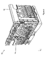
- Figure 3 is a perspective view of a quarter of the container 10. The remainder of the container 10 is symmetric.
- the container 10 is shown in the upright (or assembled) position.
- Each end wall 18 has a support 20.
- the support 20 is pivotably and slidably mounted on the end wall 18 and movable between a retracted position and a support position.
- the support 20 is shown in Figure 3 in support position, where it projects into the interior of the container 10 where it can support another container stacked thereon.
- the supports 20 project into arcuate channels 22 formed in each side wall 14. The ends of the supports 20 move in the arcuate channels 22 as the end walls 18 are collapsed onto the base 12.
- Figure 4 is an exterior view of the corner of the container 10 of Figure 3 .
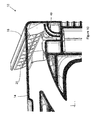
- Figure 5 is an enlarged view of the interior corner of the container 10 of Figure 3 .
- the side wall 14 includes an integrally molded deformable arm 40 (or some other deformable structure) that contacts an outer surface of the support 20.
- the arm 40 urges the support 20 away from the end wall 18 to the support position.
- FIG 6 shows a bottom perspective view of the interior corner of Figure 3 .
- the end wall 18 includes a plurality of openings 24 formed in a plurality of brackets 26.
- the support 20 includes a plurality of arms 28 (one shown in this view), each having a hinge pin 30 formed at a lower end thereof.
- the hinge pins 30 are received in the brackets 26 and are captured in the openings 24 of the brackets 26.
- the hinge pins 30 are pivotable and slidable within the openings 24 in the brackets 26.
- the hinge pins 30 define a movable axis about which the support 20 pivots. The hinge pins 30 slide to the upper end of the openings 24 when the support 20 is in the support position 20.
- the arms 28 extend at an angle inwardly and upwardly from the hinge pins 30, such that the support 20 extends further into the interior of the container 10 than the supports in some known containers.
- the end of the support 20 includes a tab 32 projected downwardly behind a rail 34 adjacent the channel 22. The tab 32 interlocks with the rail 34 to prevent the side wall 14 from deflecting outward which could otherwise permit the support 20 to slip off of the side wall 14 when a load is placed on the support 20.
- Figure 7 illustrates the support 20 moved to the retracted position within the end wall 18.
- the side wall 14 includes an upper rib 50 providing an upper contact surface that contacts the support 20 as the support 20 is moved toward the retracted position.
- the arm 28 is pivoted outwardly and the support 20 contacts the upper rib 50, which causes the hinge pin 30 to slide downward within the vertically elongated openings 24.
- the arm 40 is deflected outwardly. The arm 40 continues to urge the support 20 toward the support position, so the support 20 will return to the support position automatically upon release. Note that when the end wall 18 is collapsed onto the base, the support 20 is no longer biased toward the support position.
- Figure 8 is a section view through the side wall 14 toward the interior of the container 10.
- the arm 40 is in contact with the support 20, but in an undeflected or substantially undeflected, undeformed state.
- Figure 9 as the support 20 is pushed into the retracted position, the support 20 contacts the upper rib 50 of the side wall 14. This forces the support 20 to translate downward (i.e. the hinge pin 30 slides down within the opening 24 ( Figure 7 )).
- the arm 40 is deflected and elastically deformed outwardly until the support 20 is received in the end wall 18 in the retracted position, as shown in Figure 10 .
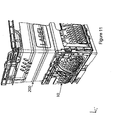
- a second container 200 can be supported on the supports 20.
- the support 20 extends further into the interior of the container 10 than some of the supports in the known containers because the support 20 is at the end of a longer, angled arm 28 that pivots and slides relative to the end wall 18 as the support 20 moves to the support position.
- FIGS 13 and 14 illustrate an alternate container 110 which embodies the invention.
- the container 110 is substantially similar to the container 10 of Figures 1-12 , and corresponding parts are referenced with the same reference number, preappended with the numeral "1.”
- the container 110 includes supports 120 pivotably and slidably mounted to the end walls 118.
- the end wall 118 includes a plurality of openings 124 formed in a plurality of brackets 126.
- the support 120 includes a plurality of arms 128 (one shown in this view), each having a hinge pin 130 formed at a lower end thereof.
- the hinge pins 130 are received in the brackets 126 and are captured in the openings 124 of the brackets 126.
- the hinge pins 130 are pivotable and slidable within the openings 124 in the brackets 126.
- the hinge pins 130 define a movable axis about which the support 120 pivots.
- the hinge pins 130 slide to the upper end of the openings 124 when the support 120 is in the support position 120.
- the arms 128 extend at an angle inwardly and upwardly from the hinge pins 130, such that the support 120 extends further into the interior of the container 110 than the supports in some known containers.
- Each support 120 further includes one or more limit arms 144 projecting outwardly and downwardly therefrom.
- a stop 146 projects outwardly from each limit arm 144.
- FIG. 14 illustrates the support 120 in the retracted position, where the stop 146 on the arm 144 of the support 120 is pivoted away from the stop 148 on the end wall 118.
Claims (12)
- Contenant repliable (10 ; 110) comprenant :une base (12) ;une paroi latérale (14) ;une paroi d'extrémité (18 ; 118) transversale à la paroi latérale (14) ;chacune de la paroi latérale (14) et de la paroi d'extrémité (18 ; 118) étant connectée de manière pivotante à la base (12) entre une position debout généralement perpendiculaire à la base (12) et une position repliée sur la base (12) ;un support (20 ; 120) déplaçable entre une position rentrée sous un bord supérieur de la paroi d'extrémité (18 ; 118) et une position de support s'étendant dans le contenant (10), le support (20 ; 120) étant monté de manière pivotante sur la paroi d'extrémité (18 ; 118) autour d'un axe de pivotement mobile ; caractérisé en ce que :l'axe de pivotement est plus proche du bord supérieur de la paroi d'extrémité (18 ; 118) lorsque le support (20 ; 120) est dans la position de support que lorsque le support (20 ; 120) est dans la position rentrée ; et en ce que le support (120) comporte un bras de limitation (144) faisant saillie depuis le support (120) et capable de s'engager avec une butée (148) formée dans la paroi d'extrémité (118), le support (120) est capable de s'engager avec la butée (148) lorsqu'il se déplace de la position rentrée dans la position de support, et l'engagement du support (120) avec la butée (148) empêche le support (120) de tourner au-delà de la position de support.
- Contenant repliable (10) selon la revendication 1, dans lequel la paroi d'extrémité (18) comporte une console (26 ; 126) sur un côté intérieur de la paroi d'extrémité (18 ; 118), la console (26 ; 126) comportant une ouverture allongée verticalement (24 ; 124) ; et
le support (20 ; 120) comporte une goupille d'articulation (30 ; 130) autour de laquelle le support (20 ; 120) pivote, la goupille d'articulation (30 ; 130) étant reçue dans l'ouverture allongée verticalement de manière à permettre au support (20 ; 120) de pivoter et de glisser. - Contenant repliable (10) selon la revendication 2, dans lequel le support comporte un bras de support (28 ; 128) s'étendant vers le haut et vers l'intérieur depuis la goupille d'articulation (30 ; 130) jusqu'à une portion de support.
- Contenant repliable (10) selon la revendication 2 ou 3, dans lequel la goupille d'articulation (30 ; 130) glisse jusqu'à une extrémité supérieure de l'ouverture allongée verticalement (24 ; 124) lorsque le support (20 ; 120) est dans la position de support.
- Contenant repliable (10) selon l'une quelconque des revendications 2 à 4, dans lequel la goupille d'articulation (30 ; 130) glisse jusqu'à une extrémité inférieure de l'ouverture allongée verticalement (24 ; 124) lorsque le support (20 ; 120) est dans la position rentrée.
- Contenant repliable (10) selon l'une quelconque des revendications précédentes, dans lequel, lorsque le support (20) est pivoté de la position de support dans la position rentrée, le support (20) vient en contact avec une nervure (50) s'étendant depuis le bord supérieur de la paroi latérale (14) et le mouvement de pivotement du support (20) est converti en un mouvement vers le bas en réponse à la mise en contact du support (20) avec la nervure (50).
- Contenant repliable (10) selon l'une quelconque des revendications précédentes, dans lequel, lorsque la paroi latérale (14) et la paroi d'extrémité (18) sont dans la position debout, le support (20) est poussé vers la position de support par un bras (40) s'étendant depuis la paroi latérale.
- Contenant repliable (10) selon la revendication 7, dans lequel, lorsque le support (20) est déplacé vers la position de support, le bras (40) vient en contact avec le support (20) de telle sorte que le bras se déplace vers un état non sollicité.
- Contenant repliable (10) selon la revendication 7 ou 8, dans lequel, lorsque le support (20) est déplacé depuis la position de support dans la position rentrée, le support (20) dévie le bras (40).
- Contenant repliable (10) selon l'une quelconque des revendications 7 à 9, comportant en outre le fait que le bras (40) est déformé élastiquement en réponse au mouvement de glissement du support (20).
- Contenant repliable (10) selon l'une quelconque des revendications précédentes, dans lequel la paroi latérale (14) comporte une nervure supérieure (50) s'étendant depuis un bord supérieur de celle-ci, et dans lequel le pivotement du support (20) depuis la position de support vers la position rentrée amène le support (20) en contact avec la nervure supérieure (50) de telle sorte que le mouvement de pivotement du support (20) soit converti en un mouvement de glissement vers le bas du support.
- Contenant (10) selon l'une quelconque des revendications précédentes, dans lequel le support (20 ; 120) est monté sur un côté intérieur de la paroi d'extrémité (18 ; 118).
Applications Claiming Priority (1)
| Application Number | Priority Date | Filing Date | Title |
|---|---|---|---|
| US11917308P | 2008-12-02 | 2008-12-02 |
Publications (2)
| Publication Number | Publication Date |
|---|---|
| EP2194001A1 EP2194001A1 (fr) | 2010-06-09 |
| EP2194001B1 true EP2194001B1 (fr) | 2013-01-23 |
Family
ID=41608169
Family Applications (1)
| Application Number | Title | Priority Date | Filing Date |
|---|---|---|---|
| EP09177790A Not-in-force EP2194001B1 (fr) | 2008-12-02 | 2009-12-02 | Conteneur compressible |
Country Status (4)
| Country | Link |
|---|---|
| US (1) | US8317045B2 (fr) |
| EP (1) | EP2194001B1 (fr) |
| CA (1) | CA2686829A1 (fr) |
| MX (1) | MX2009013122A (fr) |
Families Citing this family (6)
| Publication number | Priority date | Publication date | Assignee | Title |
|---|---|---|---|---|
| EP2289811B1 (fr) * | 2009-08-27 | 2013-05-29 | Rehrig Pacific Company | Caisse pliable |
| DE202010007099U1 (de) * | 2010-05-21 | 2010-08-26 | Surplus Systems Ug | Kiste |
| CA2751182A1 (fr) * | 2010-09-01 | 2012-03-01 | Rehrig Pacific Company | Contenant emboitable |
| GB201112660D0 (en) * | 2011-07-22 | 2011-09-07 | Linpac Allibert Ltd | Collapsible container |
| US10065763B2 (en) | 2016-09-15 | 2018-09-04 | Arena Packaging, Llc | Wall latching system |
| US11820552B2 (en) | 2019-08-26 | 2023-11-21 | Rehrig Pacific Company | Containers for oil bottles or the like |
Citations (2)
| Publication number | Priority date | Publication date | Assignee | Title |
|---|---|---|---|---|
| EP1785360A1 (fr) * | 2005-11-02 | 2007-05-16 | LINPAC Materials Handling Limited | Conteneur pliable |
| US20080116201A1 (en) * | 2006-11-17 | 2008-05-22 | Kyle Baltz | Container |
Family Cites Families (39)
| Publication number | Priority date | Publication date | Assignee | Title |
|---|---|---|---|---|
| DE1536040A1 (de) | 1966-10-12 | 1969-12-11 | Wolfgang Friedrich | Zusammenklappbarer Transportkasten |
| GB1529485A (en) | 1976-08-12 | 1978-10-18 | Worldwide Plastics Dev | Collapsible container |
| NL7905105A (nl) | 1979-06-29 | 1980-12-31 | Wavin Bv | Stapelbare en nestbare bak uit kunststof. |
| FR2468510A1 (fr) * | 1979-10-08 | 1981-05-08 | Allibert Exploitation | Bac emboitable |
| US4573577A (en) | 1980-02-08 | 1986-03-04 | Buckhorn Material Handling Group Inc. | Stackable container |
| EP0073357A3 (fr) | 1981-08-19 | 1984-02-22 | NESPAK S.p.A. Società Generale per L'Imballaggio | Caisse, assemblable et empilable, en matière plastique et machine pour l'assemblage |
| US4423813A (en) | 1982-05-24 | 1984-01-03 | Pinckney Molded Plastics, Inc. | Multilevel stacking container |
| GB2124588B (en) | 1982-08-04 | 1986-02-19 | Crayonne Ltd | Stacking/nesting tray |
| GB2171980B (en) | 1982-10-26 | 1987-03-11 | Paxton C G Ltd | Stacking/nesting containers |
| GB2129401B (en) | 1982-10-26 | 1987-03-11 | Paxton C G Ltd | Stacking/nesting containers |
| GB8314141D0 (en) | 1983-05-21 | 1983-06-29 | Paxton Ltd C G | Hinges |
| DE3511321A1 (de) | 1985-03-28 | 1986-10-02 | Seitz, Peter, 6550 Bad Kreuznach | Stapelbare behaelter |
| DE3521894A1 (de) | 1985-06-19 | 1987-01-02 | Peter Seitz | Stapelbarer behaelter |
| US4901859A (en) | 1987-07-04 | 1990-02-20 | Jones David L | Container |
| EP0341074A1 (fr) | 1988-05-06 | 1989-11-08 | Styropack (Uk) Limited | Récipient |
| US4917255A (en) | 1989-02-24 | 1990-04-17 | J.I.T. Corporation | Collapsible container |
| US5076457A (en) | 1989-06-22 | 1991-12-31 | Tetra Pak Holdings S.A. | Folding crate for holding packages |
| GB2296009B (en) | 1992-02-15 | 1996-09-04 | Mckechnie Uk Ltd | Container |
| FR2702198A1 (fr) | 1993-03-01 | 1994-09-09 | Raef Sarl Location | Cageot repliable pour le transport de fruits et légumes. |
| IT242479Y1 (it) | 1996-01-18 | 2001-06-14 | Tontarelli Sergio | Cassetta stampata in materiali plastici dotata di sponde ribaltabiliverso l'interno |
| GB2340485B (en) * | 1996-03-22 | 2000-08-23 | Mckechnie Uk Ltd | Containers |
| WO1997049613A1 (fr) | 1996-06-24 | 1997-12-31 | Schoeller International Engineering S.A. | Charniere et verrouillage des parois laterales d'un recipient repliable en forme de caisse |
| WO1998056668A1 (fr) | 1997-06-11 | 1998-12-17 | Mckechnie Uk Limited | Contenant empilable et emboitable |
| IT244855Y1 (it) | 1998-06-05 | 2002-03-14 | Tontarelli Sergio | Cassetta stampata in plastica dotata di pareti abbattibili e dimezzi particolarmente affidabili per lo stabile bloccaggio delle |
| SE514353C2 (sv) | 1998-11-06 | 2001-02-12 | Arca Systems Ab | Fällbart emballage |
| SE521473C2 (sv) | 1999-04-30 | 2003-11-04 | Arca Systems Ab | Fällbar låda |
| DE19939019A1 (de) | 1999-08-18 | 2001-02-22 | Schoeller Plast Ag | Stapelbarer Klappbehälter |
| JP3707973B2 (ja) | 1999-11-09 | 2005-10-19 | 三甲株式会社 | 折り畳みコンテナー |
| WO2001044060A1 (fr) | 1999-12-16 | 2001-06-21 | C.G. Paxton Ltd. | Recipients |
| DE20002537U1 (de) | 2000-02-12 | 2001-06-13 | Zimmermann Jens | Stapelsystem für Transportbehälter |
| US6938772B2 (en) | 2002-06-04 | 2005-09-06 | Rehrig Pacific Company | Portable storage container |
| US7234598B2 (en) * | 2004-03-16 | 2007-06-26 | Schaefer Systems International, Inc. | Material handling container with card holder |
| US20070095842A1 (en) | 2005-11-01 | 2007-05-03 | Apps William P | Container |
| US7357269B2 (en) | 2005-11-01 | 2008-04-15 | Rehrig Pacific Company | Container |
| US20070272579A1 (en) * | 2006-05-24 | 2007-11-29 | Rehrig Pacific Company | Collapsible crate with support members |
| AU2007322997A1 (en) * | 2006-11-22 | 2008-05-29 | Sergio Tontarelli | Box with collapsible walls designed to stack a corresponding box with lower dimensions |
| USD600020S1 (en) | 2007-04-02 | 2009-09-15 | Linpac Allibert Limited | Collapsible container |
| MX2009001811A (es) | 2008-02-18 | 2009-09-03 | Rehrig Pacific Co | Contenedor plegable. |
| US8091706B2 (en) * | 2008-08-25 | 2012-01-10 | Rehrig Pacific Company | Container |
-
2009
- 2009-12-02 US US12/629,344 patent/US8317045B2/en active Active
- 2009-12-02 CA CA2686829A patent/CA2686829A1/fr not_active Abandoned
- 2009-12-02 MX MX2009013122A patent/MX2009013122A/es not_active Application Discontinuation
- 2009-12-02 EP EP09177790A patent/EP2194001B1/fr not_active Not-in-force
Patent Citations (2)
| Publication number | Priority date | Publication date | Assignee | Title |
|---|---|---|---|---|
| EP1785360A1 (fr) * | 2005-11-02 | 2007-05-16 | LINPAC Materials Handling Limited | Conteneur pliable |
| US20080116201A1 (en) * | 2006-11-17 | 2008-05-22 | Kyle Baltz | Container |
Also Published As
| Publication number | Publication date |
|---|---|
| EP2194001A1 (fr) | 2010-06-09 |
| MX2009013122A (es) | 2010-06-25 |
| US8317045B2 (en) | 2012-11-27 |
| US20100133267A1 (en) | 2010-06-03 |
| CA2686829A1 (fr) | 2010-06-02 |
Similar Documents
| Publication | Publication Date | Title |
|---|---|---|
| EP2194001B1 (fr) | Conteneur compressible | |
| EP2194000B1 (fr) | Récipient doté de supports rétractables | |
| EP2058238B1 (fr) | Conteneur pliable | |
| US20070095842A1 (en) | Container | |
| EP2003062B1 (fr) | Conteneur pliable avec dispositif d'empilage | |
| EP2311744B1 (fr) | Conteneur compressible | |
| EP2159159B1 (fr) | Conteneur | |
| EP2390199B1 (fr) | Récipient pliant comprenant une structure d'empilement à deux hauteurs | |
| EP2241511A1 (fr) | Conteneur pliable | |
| EP2039615B1 (fr) | Récipient pliable | |
| US20100065558A1 (en) | Collapsible crate with multiple position support | |
| EP2145829B1 (fr) | Conteneur repliable | |
| EP2098456A1 (fr) | Conteneur compressible | |
| EP2277789A1 (fr) | Conteneur pliable |
Legal Events
| Date | Code | Title | Description |
|---|---|---|---|
| PUAI | Public reference made under article 153(3) epc to a published international application that has entered the european phase |
Free format text: ORIGINAL CODE: 0009012 |
|
| AK | Designated contracting states |
Kind code of ref document: A1 Designated state(s): AT BE BG CH CY CZ DE DK EE ES FI FR GB GR HR HU IE IS IT LI LT LU LV MC MK MT NL NO PL PT RO SE SI SK SM TR |
|
| 17P | Request for examination filed |
Effective date: 20100803 |
|
| 17Q | First examination report despatched |
Effective date: 20100930 |
|
| RIC1 | Information provided on ipc code assigned before grant |
Ipc: B65D 6/18 20060101ALI20120605BHEP Ipc: B65D 21/06 20060101AFI20120605BHEP |
|
| GRAP | Despatch of communication of intention to grant a patent |
Free format text: ORIGINAL CODE: EPIDOSNIGR1 |
|
| GRAS | Grant fee paid |
Free format text: ORIGINAL CODE: EPIDOSNIGR3 |
|
| GRAA | (expected) grant |
Free format text: ORIGINAL CODE: 0009210 |
|
| AK | Designated contracting states |
Kind code of ref document: B1 Designated state(s): AT BE BG CH CY CZ DE DK EE ES FI FR GB GR HR HU IE IS IT LI LT LU LV MC MK MT NL NO PL PT RO SE SI SK SM TR |
|
| REG | Reference to a national code |
Ref country code: GB Ref legal event code: FG4D |
|
| REG | Reference to a national code |
Ref country code: CH Ref legal event code: EP |
|
| REG | Reference to a national code |
Ref country code: AT Ref legal event code: REF Ref document number: 594814 Country of ref document: AT Kind code of ref document: T Effective date: 20130215 Ref country code: CH Ref legal event code: EP |
|
| REG | Reference to a national code |
Ref country code: IE Ref legal event code: FG4D |
|
| REG | Reference to a national code |
Ref country code: DE Ref legal event code: R096 Ref document number: 602009012960 Country of ref document: DE Effective date: 20130321 |
|
| REG | Reference to a national code |
Ref country code: AT Ref legal event code: MK05 Ref document number: 594814 Country of ref document: AT Kind code of ref document: T Effective date: 20130123 |
|
| REG | Reference to a national code |
Ref country code: LT Ref legal event code: MG4D |
|
| REG | Reference to a national code |
Ref country code: NL Ref legal event code: VDEP Effective date: 20130123 |
|
| PG25 | Lapsed in a contracting state [announced via postgrant information from national office to epo] |
Ref country code: IS Free format text: LAPSE BECAUSE OF FAILURE TO SUBMIT A TRANSLATION OF THE DESCRIPTION OR TO PAY THE FEE WITHIN THE PRESCRIBED TIME-LIMIT Effective date: 20130523 Ref country code: NO Free format text: LAPSE BECAUSE OF FAILURE TO SUBMIT A TRANSLATION OF THE DESCRIPTION OR TO PAY THE FEE WITHIN THE PRESCRIBED TIME-LIMIT Effective date: 20130423 Ref country code: BE Free format text: LAPSE BECAUSE OF FAILURE TO SUBMIT A TRANSLATION OF THE DESCRIPTION OR TO PAY THE FEE WITHIN THE PRESCRIBED TIME-LIMIT Effective date: 20130123 Ref country code: BG Free format text: LAPSE BECAUSE OF FAILURE TO SUBMIT A TRANSLATION OF THE DESCRIPTION OR TO PAY THE FEE WITHIN THE PRESCRIBED TIME-LIMIT Effective date: 20130423 Ref country code: SE Free format text: LAPSE BECAUSE OF FAILURE TO SUBMIT A TRANSLATION OF THE DESCRIPTION OR TO PAY THE FEE WITHIN THE PRESCRIBED TIME-LIMIT Effective date: 20130123 Ref country code: ES Free format text: LAPSE BECAUSE OF FAILURE TO SUBMIT A TRANSLATION OF THE DESCRIPTION OR TO PAY THE FEE WITHIN THE PRESCRIBED TIME-LIMIT Effective date: 20130504 Ref country code: AT Free format text: LAPSE BECAUSE OF FAILURE TO SUBMIT A TRANSLATION OF THE DESCRIPTION OR TO PAY THE FEE WITHIN THE PRESCRIBED TIME-LIMIT Effective date: 20130123 Ref country code: LT Free format text: LAPSE BECAUSE OF FAILURE TO SUBMIT A TRANSLATION OF THE DESCRIPTION OR TO PAY THE FEE WITHIN THE PRESCRIBED TIME-LIMIT Effective date: 20130123 |
|
| PG25 | Lapsed in a contracting state [announced via postgrant information from national office to epo] |
Ref country code: LV Free format text: LAPSE BECAUSE OF FAILURE TO SUBMIT A TRANSLATION OF THE DESCRIPTION OR TO PAY THE FEE WITHIN THE PRESCRIBED TIME-LIMIT Effective date: 20130123 Ref country code: PT Free format text: LAPSE BECAUSE OF FAILURE TO SUBMIT A TRANSLATION OF THE DESCRIPTION OR TO PAY THE FEE WITHIN THE PRESCRIBED TIME-LIMIT Effective date: 20130523 Ref country code: NL Free format text: LAPSE BECAUSE OF FAILURE TO SUBMIT A TRANSLATION OF THE DESCRIPTION OR TO PAY THE FEE WITHIN THE PRESCRIBED TIME-LIMIT Effective date: 20130123 Ref country code: SI Free format text: LAPSE BECAUSE OF FAILURE TO SUBMIT A TRANSLATION OF THE DESCRIPTION OR TO PAY THE FEE WITHIN THE PRESCRIBED TIME-LIMIT Effective date: 20130123 Ref country code: FI Free format text: LAPSE BECAUSE OF FAILURE TO SUBMIT A TRANSLATION OF THE DESCRIPTION OR TO PAY THE FEE WITHIN THE PRESCRIBED TIME-LIMIT Effective date: 20130123 Ref country code: PL Free format text: LAPSE BECAUSE OF FAILURE TO SUBMIT A TRANSLATION OF THE DESCRIPTION OR TO PAY THE FEE WITHIN THE PRESCRIBED TIME-LIMIT Effective date: 20130123 Ref country code: GR Free format text: LAPSE BECAUSE OF FAILURE TO SUBMIT A TRANSLATION OF THE DESCRIPTION OR TO PAY THE FEE WITHIN THE PRESCRIBED TIME-LIMIT Effective date: 20130424 |
|
| PG25 | Lapsed in a contracting state [announced via postgrant information from national office to epo] |
Ref country code: HR Free format text: LAPSE BECAUSE OF FAILURE TO SUBMIT A TRANSLATION OF THE DESCRIPTION OR TO PAY THE FEE WITHIN THE PRESCRIBED TIME-LIMIT Effective date: 20130123 |
|
| PG25 | Lapsed in a contracting state [announced via postgrant information from national office to epo] |
Ref country code: SK Free format text: LAPSE BECAUSE OF FAILURE TO SUBMIT A TRANSLATION OF THE DESCRIPTION OR TO PAY THE FEE WITHIN THE PRESCRIBED TIME-LIMIT Effective date: 20130123 Ref country code: EE Free format text: LAPSE BECAUSE OF FAILURE TO SUBMIT A TRANSLATION OF THE DESCRIPTION OR TO PAY THE FEE WITHIN THE PRESCRIBED TIME-LIMIT Effective date: 20130123 Ref country code: CZ Free format text: LAPSE BECAUSE OF FAILURE TO SUBMIT A TRANSLATION OF THE DESCRIPTION OR TO PAY THE FEE WITHIN THE PRESCRIBED TIME-LIMIT Effective date: 20130123 Ref country code: DK Free format text: LAPSE BECAUSE OF FAILURE TO SUBMIT A TRANSLATION OF THE DESCRIPTION OR TO PAY THE FEE WITHIN THE PRESCRIBED TIME-LIMIT Effective date: 20130123 Ref country code: RO Free format text: LAPSE BECAUSE OF FAILURE TO SUBMIT A TRANSLATION OF THE DESCRIPTION OR TO PAY THE FEE WITHIN THE PRESCRIBED TIME-LIMIT Effective date: 20130123 |
|
| PG25 | Lapsed in a contracting state [announced via postgrant information from national office to epo] |
Ref country code: CY Free format text: LAPSE BECAUSE OF FAILURE TO SUBMIT A TRANSLATION OF THE DESCRIPTION OR TO PAY THE FEE WITHIN THE PRESCRIBED TIME-LIMIT Effective date: 20130123 |
|
| PLBE | No opposition filed within time limit |
Free format text: ORIGINAL CODE: 0009261 |
|
| STAA | Information on the status of an ep patent application or granted ep patent |
Free format text: STATUS: NO OPPOSITION FILED WITHIN TIME LIMIT |
|
| PG25 | Lapsed in a contracting state [announced via postgrant information from national office to epo] |
Ref country code: IT Free format text: LAPSE BECAUSE OF FAILURE TO SUBMIT A TRANSLATION OF THE DESCRIPTION OR TO PAY THE FEE WITHIN THE PRESCRIBED TIME-LIMIT Effective date: 20130123 |
|
| 26N | No opposition filed |
Effective date: 20131024 |
|
| REG | Reference to a national code |
Ref country code: DE Ref legal event code: R097 Ref document number: 602009012960 Country of ref document: DE Effective date: 20131024 |
|
| PG25 | Lapsed in a contracting state [announced via postgrant information from national office to epo] |
Ref country code: MC Free format text: LAPSE BECAUSE OF FAILURE TO SUBMIT A TRANSLATION OF THE DESCRIPTION OR TO PAY THE FEE WITHIN THE PRESCRIBED TIME-LIMIT Effective date: 20130123 |
|
| REG | Reference to a national code |
Ref country code: CH Ref legal event code: PL |
|
| PG25 | Lapsed in a contracting state [announced via postgrant information from national office to epo] |
Ref country code: LU Free format text: LAPSE BECAUSE OF FAILURE TO SUBMIT A TRANSLATION OF THE DESCRIPTION OR TO PAY THE FEE WITHIN THE PRESCRIBED TIME-LIMIT Effective date: 20131202 |
|
| REG | Reference to a national code |
Ref country code: IE Ref legal event code: MM4A |
|
| PG25 | Lapsed in a contracting state [announced via postgrant information from national office to epo] |
Ref country code: IE Free format text: LAPSE BECAUSE OF NON-PAYMENT OF DUE FEES Effective date: 20131202 Ref country code: CH Free format text: LAPSE BECAUSE OF NON-PAYMENT OF DUE FEES Effective date: 20131231 Ref country code: LI Free format text: LAPSE BECAUSE OF NON-PAYMENT OF DUE FEES Effective date: 20131231 |
|
| PGFP | Annual fee paid to national office [announced via postgrant information from national office to epo] |
Ref country code: GB Payment date: 20141126 Year of fee payment: 6 Ref country code: DE Payment date: 20141125 Year of fee payment: 6 |
|
| PGFP | Annual fee paid to national office [announced via postgrant information from national office to epo] |
Ref country code: FR Payment date: 20141208 Year of fee payment: 6 |
|
| PG25 | Lapsed in a contracting state [announced via postgrant information from national office to epo] |
Ref country code: SM Free format text: LAPSE BECAUSE OF FAILURE TO SUBMIT A TRANSLATION OF THE DESCRIPTION OR TO PAY THE FEE WITHIN THE PRESCRIBED TIME-LIMIT Effective date: 20130123 |
|
| PG25 | Lapsed in a contracting state [announced via postgrant information from national office to epo] |
Ref country code: TR Free format text: LAPSE BECAUSE OF FAILURE TO SUBMIT A TRANSLATION OF THE DESCRIPTION OR TO PAY THE FEE WITHIN THE PRESCRIBED TIME-LIMIT Effective date: 20130123 |
|
| PG25 | Lapsed in a contracting state [announced via postgrant information from national office to epo] |
Ref country code: HU Free format text: LAPSE BECAUSE OF FAILURE TO SUBMIT A TRANSLATION OF THE DESCRIPTION OR TO PAY THE FEE WITHIN THE PRESCRIBED TIME-LIMIT; INVALID AB INITIO Effective date: 20091202 Ref country code: MK Free format text: LAPSE BECAUSE OF FAILURE TO SUBMIT A TRANSLATION OF THE DESCRIPTION OR TO PAY THE FEE WITHIN THE PRESCRIBED TIME-LIMIT Effective date: 20130123 |
|
| PG25 | Lapsed in a contracting state [announced via postgrant information from national office to epo] |
Ref country code: MT Free format text: LAPSE BECAUSE OF FAILURE TO SUBMIT A TRANSLATION OF THE DESCRIPTION OR TO PAY THE FEE WITHIN THE PRESCRIBED TIME-LIMIT Effective date: 20130123 |
|
| REG | Reference to a national code |
Ref country code: DE Ref legal event code: R119 Ref document number: 602009012960 Country of ref document: DE |
|
| GBPC | Gb: european patent ceased through non-payment of renewal fee |
Effective date: 20151202 |
|
| REG | Reference to a national code |
Ref country code: FR Ref legal event code: ST Effective date: 20160831 |
|
| PG25 | Lapsed in a contracting state [announced via postgrant information from national office to epo] |
Ref country code: DE Free format text: LAPSE BECAUSE OF NON-PAYMENT OF DUE FEES Effective date: 20160701 Ref country code: GB Free format text: LAPSE BECAUSE OF NON-PAYMENT OF DUE FEES Effective date: 20151202 |
|
| PG25 | Lapsed in a contracting state [announced via postgrant information from national office to epo] |
Ref country code: FR Free format text: LAPSE BECAUSE OF NON-PAYMENT OF DUE FEES Effective date: 20151231 |