EP0402794B1 - Positionsmesseinrichtung mittels Kodierung durch Beugung - Google Patents
Positionsmesseinrichtung mittels Kodierung durch Beugung Download PDFInfo
- Publication number
- EP0402794B1 EP0402794B1 EP90110909A EP90110909A EP0402794B1 EP 0402794 B1 EP0402794 B1 EP 0402794B1 EP 90110909 A EP90110909 A EP 90110909A EP 90110909 A EP90110909 A EP 90110909A EP 0402794 B1 EP0402794 B1 EP 0402794B1
- Authority
- EP
- European Patent Office
- Prior art keywords
- grating
- laser
- laser beam
- diffracted
- beams
- Prior art date
- Legal status (The legal status is an assumption and is not a legal conclusion. Google has not performed a legal analysis and makes no representation as to the accuracy of the status listed.)
- Expired - Lifetime
Links
- 238000001514 detection method Methods 0.000 claims description 16
- 238000000034 method Methods 0.000 claims description 9
- 238000012360 testing method Methods 0.000 claims description 5
- 230000003287 optical effect Effects 0.000 claims description 4
- 230000001427 coherent effect Effects 0.000 claims 1
- 230000000694 effects Effects 0.000 description 9
- 238000005259 measurement Methods 0.000 description 6
- 238000013459 approach Methods 0.000 description 4
- 230000010363 phase shift Effects 0.000 description 2
- 239000000758 substrate Substances 0.000 description 2
- 238000010420 art technique Methods 0.000 description 1
- 230000003247 decreasing effect Effects 0.000 description 1
- 238000013461 design Methods 0.000 description 1
- 238000011161 development Methods 0.000 description 1
- 238000006073 displacement reaction Methods 0.000 description 1
- CPBQJMYROZQQJC-UHFFFAOYSA-N helium neon Chemical compound [He].[Ne] CPBQJMYROZQQJC-UHFFFAOYSA-N 0.000 description 1
- 230000002040 relaxant effect Effects 0.000 description 1
- 230000035945 sensitivity Effects 0.000 description 1
Images

Classifications
-
- G—PHYSICS
- G01—MEASURING; TESTING
- G01D—MEASURING NOT SPECIALLY ADAPTED FOR A SPECIFIC VARIABLE; ARRANGEMENTS FOR MEASURING TWO OR MORE VARIABLES NOT COVERED IN A SINGLE OTHER SUBCLASS; TARIFF METERING APPARATUS; MEASURING OR TESTING NOT OTHERWISE PROVIDED FOR
- G01D5/00—Mechanical means for transferring the output of a sensing member; Means for converting the output of a sensing member to another variable where the form or nature of the sensing member does not constrain the means for converting; Transducers not specially adapted for a specific variable
- G01D5/26—Mechanical means for transferring the output of a sensing member; Means for converting the output of a sensing member to another variable where the form or nature of the sensing member does not constrain the means for converting; Transducers not specially adapted for a specific variable characterised by optical transfer means, i.e. using infrared, visible, or ultraviolet light
- G01D5/32—Mechanical means for transferring the output of a sensing member; Means for converting the output of a sensing member to another variable where the form or nature of the sensing member does not constrain the means for converting; Transducers not specially adapted for a specific variable characterised by optical transfer means, i.e. using infrared, visible, or ultraviolet light with attenuation or whole or partial obturation of beams of light
- G01D5/34—Mechanical means for transferring the output of a sensing member; Means for converting the output of a sensing member to another variable where the form or nature of the sensing member does not constrain the means for converting; Transducers not specially adapted for a specific variable characterised by optical transfer means, i.e. using infrared, visible, or ultraviolet light with attenuation or whole or partial obturation of beams of light the beams of light being detected by photocells
- G01D5/36—Forming the light into pulses
- G01D5/38—Forming the light into pulses by diffraction gratings
Definitions
- the present invention is generally concerned with position detection and more specifically, with position detection using light-beams such as produced by lasers in conjunction with a grating whose movement or position is being detected. Even more specifically, the invention is related to the effective change in phase of a laser signal after passing through a grating and producing diffracted orders higher than zero, and using detection apparatus to measure the difference between the zero order beam and one of the higher order beams for use in accurately measuring displacement of the grating.
- Prior art position detector apparatus have used gratings as an encoder for linear or angular measurements and comprises a common technique used in many commercial devices.
- One such prior art device is illustrated in a paper authored by myself and S. Holly in the proceedings of SPIE - The International Society For Optical Engineering, Volume 887, as presented January 14, 1988, in Los Angeles, California, in the Acquisition, Tracking and Pointing group. The title of the article was, "Development of An Interferometric Encoder For High Resolution Angular Measurements".
- the prior art technology of this paper concerns heterodyne detection.
- the grating for many prior art devices is produced holographically by two beams which interfere at an angle of incidence theta ( ⁇ ), on a substrate which retains the image of the laser pattern.
- the spacing of the grating will be an amount G which equals lambda ( ⁇ ) divided by (2 times sine of the angle theta) where lambda is the wavelength of the beam
- Prior art techniques have compared the position of a reference grating with one being produced at the time of measurement by the laser involved. Data from the two gratings are then compared in a phase measurement type test to provide an indication of position.
- a device such as a computer can keep track of the phase changes for total number of cycles changed to get absolute position relative to a reference.
- the present invention involves the discovery that the grating can have a spacing comparable to or less than the wavelength, one aspect of the present invention allows the gratings to be produced by a short wavelength, (more expensive) laser from the fringe effects produced by the interference of two such lasers and then this grating be used with a longer wavelength but less expensive laser in combination with a low cost phase detector to produce the measurement desired.
- a further realization in the present invention is that if a diffracted beam is redirected through the grating N times before being detected, the change in phase will be N times the change in phase of a single pass system.
- a multipass system using only the multipass concept portion of the present invention is illustrated by an article in Motion magazine, July/August, 1986, authored by Nishimura and Ishizuka.
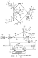
- a laser source supplies a light beam signal on a path or beam labeled 10.
- This beam is passed through a block 12 labeled AOM for acouso-optic modulator which superimposes a modulated signal on the laser beam at a frequency that can be easily detected.
- the laser beam had a wavelength of 633 nanometers which is approximately equivalent to 4.7 x 10¹² megahertz.
- the modulating frequency from the AOM 12 may be a much lower value such as 40 megahertz.
- a second laser beam 14 is shown passing through a second AOM 16 and producing an output beam 18 modulated at 41 megahertz.
- the source 14 may be the same as source 10 and redirected using mirrors or may be a separate source if it is in phase with 10.
- the light beam 18 after passing through a grating 20 continues as a zero order beam 22 and a portion of the original beam 18 is diffracted as an N order beam such as first order beam 24.
- the output of AOM 12 is supplied as a zero order beam 26 to the grating 20 and after passage through the grating 20, continues as a zero order beam 28 and a diffracted beam 30.
- the phase of the diffracted beams 24 and 30 change phase in opposite directions for a given direction of movement of grating 20.
- beam 30 may be any of N orders but for the purposes of explanation will be a first order beam.
- the beam 30 is deflected from a mirror 32 to a beam splitter 34.
- the beam 24 is reflected off a further mirror 36 and is also supplied to beam splitter 34.
- the signals are combined to produce a fringe pattern which is detected with a detecting device of the square law type such as a photo detector.
- Detector 38 is labeled as the detector of the fringe pattern.
- a portion of the beam reflected from beam 32 is labeled as beam 40 and is the remaining portion of beam 30 which is still in existence after the combining or mixing process.
- Beam 40 would be supplied to some type of beam dump 42 and would be unused.
- the output of detector 38 would be an electrical signal indicative of the difference frequency between the modulated signal on beams 24 and 30. This output is labeled 44.
- the beams 22 and 28 are combined in a beam splitter generally designated as 46 and a fringe pattern resulting from the combination of 22 and 28 is detected by a detector 48 which operates in a manner similar to that of 38.
- a reference signal output is obtained from the detector 48 and is supplied on a lead 50.
- the extension of light beam 28 that is the unused portion, is also supplied to a beam dump 52.
- a laser 75 is shown supplying a light beam to a beam splitter generally designated as 77 and the beam of light is output as two separate beams 79 and 81 from beam splitter 77.
- Beam 79 goes through a modulating device such as an AOM 83 and then passes through a grate 85 where it continues as a beam 87 of zero order and a first order beam 89.
- the beam 89 is reflected by a pair of mirrors generally designated as 91 and returned to the grate 85 where again a zero order beam continues, and is dissipated in a beam dump and a further deflected beam of the first order 93 is returned to beam splitter 77.
- the beam 81 is passed through a further modulator (AOM) 95 which modulates the signal at a slightly different frequency than does the modulator 83 and provides an output 97.
- the output 97 passes through grating 85 and produces a zero order beam 99 and a first order diffracted beam 101.
- Beam 101 is reflected from a pair of mirrors generally designated as 103 and is returned as a beam 105 which is again passed through grating 85.
- a first order component of beam 105 is designated as 107 and it is returned to beam splitter 77.
- the beams 93 and 107 produce a fringe effect which is detected by a detector 109.
- Detector 109 provides an electrical signal on a lead 111 to a phase detector 113.
- the beam 87 is reflected by a mirror 115 and supplied to a beam splitter generally designated as 117.
- the beam 99 is reflected by a mirror 119 and also supplied to beam splitter 117.
- the two beams received by beam splitter 117 interfere to produce a fringe effect and the fringe effect is detected by detector 121 and an output signal is produced on lead 123 and supplied to phase detector 113.
- the output of phase detector 113 is a voltage proportional to the phase difference between signals from 121 and 111, and this provides a total movement indication of the grating 85.
- This signal can be converted to a voltage by block 125 and stored in a computer or viewed on any voltage measuring device such as an oscilloscope 127.
- the beam starting out as 79 passes through the grating 85 on two separate passes each of which has the same relative angle for a given direction of movement of the grating 85.
- the two beams which pass through grating 85 as a result of initial beam 81 are aligned such that they have a component which is opposite the previously referenced beam. Movement of the grating 85 produces an effect similar to a Doppler effect in phase shifting the modulating frequency of the light beam passing through. This phenomena is well-known in the art and may be verified in many reference books such as on Page 864 of a book entitled, "Applied Optics - A Guide To Optical System Design/Volume 2", by Leo Levi, copyrighted in 1980 and published by John Wiley and Sons.
- a laser 150 supplies a laser beam through an acousto-optic modulator 152 to provide an output zero order beam 154 and a first order beam 156.
- the beam 154 goes directly to a beam splitter 158 while the first order beam 156 is supplied to a grating 160 where it is output as a beam 162 which continues to a beam dump 164 and a diffracted first order beam 166 is passed to the beam splitter 158.
- the two beams 154 and 166 interfere or combine in the splitter 158 and produce a fringe effect output which is detected by a detector 170.
- the continuation of beam 154 is passed to and terminated by a beam dump 172.
- An electrical output of detector 170 is supplied to a dash line block generally designated as 174 which contains an RF amplifier 176.
- An output of the amplifier 176 is supplied to a mixer 178 whose output is supplied to a phase detector 180.
- a 40 megahertz signal is supplied both to the AOM 152 to provide modulation for it and to a mixer 182 within block 174.
- a 41 megahertz signal is supplied on a lead 184 to the two mixers 178 and 182.
- An output of phase detector 180 is supplied on a lead 186 which is indicative of the phase difference between the reference beam 154 which does not pass through grating 160 and the beam 156 which has a diffracted output 166 after passing through grating 160.
- the grating 20 can be produced holographically by two beams which interfere at an angle of incidence on a substrate which retains the image of the interference pattern.
- the spacing is a function of the wavelength of the beams and the angle of incidence according to well-known formulas.
- An ultraviolet laser having a wavelength of 300 nanometers could be used to produce a spacing on a grating at 300 nanometers where the angle of incidence is 30 degrees.
- a cheaper laser such as a helium neon laser with a wavelength of 633 nanometers could be used to provide the laser beams 10 and 14. It may be assumed that each of the acoustic modulators 12 and 16 modulate the main laser beams at slightly different values which, for purposes of discussion, might be 40 and 41 megahertz.
- the beams 18 and 26 will each have a basic wavelength of 633 nanometers which is approximately equivalent to 4.7 times 1012 megahertz with a superimposed ripple of about 40 megahertz on this lightwave.
- a zero order beam 22 appears at the output side in line with the beam 18.
- a higher order beam such as a first order beam 24 is produced from diffraction.
- the first order beam has the least phase shift in the diffraction and thus, if the intensity of an even higher order beam can be detected (as is the case for phase gratings or specially designed sinusoidal gratings), more phase shift is involved and thus, from the electrical phase detection standpoint, it is easier to detect a small movement of the grating 20.
- the beam 22, which is the zero order extension of beam 18, is combined in the beam splitter 46 with the zero order extension 28 of the beam 26.
- the interference or combination of the two beams 22 and 28 within the beam splitter 46 produces a fringe pattern which is detected by a square law detector such as a photodiode within detector 48.
- An electrical output signal is produced on lead 50 indicative of the difference between base frequency 40 and 41 megahertz signals modulated onto the original light beams by the AOM's 12 and 16.
- the diffracted beam 24 is reflected by mirror 36 to a beam splitter 34 where it combines with or interferes with a similar beam diffracted from beam 26 which is shown as beam 30 after being reflected from mirror 32.
- An interference or fringe pattern is produced by beam splitter 34 and the combination of the two incoming light beams, and this fringe pattern is detected by detector 38 and output on lead 44 as a signal which is very close to the one megahertz difference signal output by detector 48 but is phase shifted in accordance with the position of the grate 20.
- the difference in phase between the signals 44 and 50 can never exceed 2 pi, unless a phase counter is added which can count two pi changes, as we have used in our heterodyne systems.
- phase change at output 44 is twice as much as would be indicated by movement of grating 20. In other words, if the movement of grating 20 was 75 nanometers or 1/4 the spacing, then the phase change at output 44 would be pi or 180 degrees of phase difference with respect to the signal on lead 50.
- Figure 2 The operation of Figure 2 is relatively straightforward once Figure 1 is understood in that the laser beam from laser 75 is split into two separate components 79 and 81 modulated at two different frequencies such as 40 and 41 megahertz by the acoustic modulators 83 and 95. Each of these modulated light beams is then sent through the grating, reflected and returned through the grating to be combined within splitter 77. The fringe effect that is produced upon the combining is detected by detector 109 to produce a movement output signal on lead 111. The original modulated beams as appear at the output of modulators 83 and 95 have a component which is reflected by mirrors 115 and 119 wherein they are combined in splitter 117 and applied to detector 121.
- Detector 121 has an output which is primarily equivalent to the difference between the modulating signals applied by the two modulators 83 and 95 or, in other words, a one megahertz signal which is always within one cycle or one complete phase change of the signal appearing at the output of detector 109.
- the phase detector 113 detects the phase difference at any point in time between the reference detector 121 and the test detector 109. Thus, an accumulated summary of the incremental phase changes is then stored or sent to 127 indicative of the exact position of grating 85 with respect to an initial reference.
- the grating comprises part of a disk which is being measured for radial movement, or in other words, to measure angular motion, the only requirement is that the plane of incidence and diffraction be perpendicular to the disk upon which a grating has been produced.
- the single pass version of Figure 3 operates in a manner extremely similar to that described previously for Figures 1 and 2.
- the laser beam from laser 150 is passed through the acoustic modulator 152 and provides as an output a zero order beam represented by indicator 154 which is passed directly to the beam splitter 158 and an N order beam such as first order which is represented by 156.
- indicator 154 being the zero order beam is not modulated by AOM
- beam 156 carries the AOM modulation frequency of 40 megahertz.
- the diffracted portion of the beam represented as 166 will be of a phase relative to the beam 154 in accordance with the position of the grating 160.
- the incident extension of beam 156 which is labeled 162 is merely terminated in a beam dump 164.
- the beam splitter 158 combines the two beams 154 and 166 and through the fringe effect and modulating difference, provides an output which is detected as moving fringes by detector 170.
- the output of detector 170 is indicative of the phase difference between the two beams 154 and 166 and this difference as previously indicated, is as a result of the absolute position of the grating 160.
- the two signals which have a base of 40 megahertz as illustrated in this drawing, are then mixed in respective mixers with a 41 megahertz signal 184.
- the signal source 184 is providing a constant reference for the two mixers.
- the output signals of the two mixers are phase detected by phase detector 180 which then provides an output on 186 to be supplied to some type of accumulator such as 125 in Figure 2.
- the present invention is directed to a concept which either greatly increases the accuracy of motion detection over prior art, or greatly reduces the complexity of the electronic phase detecting apparatus for a given accuracy with respect to the prior art or some intermediate combination of both. This feat is accomplished by utilizing multiple passes of a laser beam through a grating, or using higher order diffracted beams than the first order or both.
- a further aspect of the invention is the realization that the spacing of the grating can be equal to or less than the wavelength of the laser thereby further decreasing the detector phase resolution requirements of the electronic portion of the circuit for a given frequency laser beam generating device.
Landscapes
- Physics & Mathematics (AREA)
- General Physics & Mathematics (AREA)
- Optical Transform (AREA)
Claims (7)
- Verfahren zum Ermitteln der Verstellung eines Gitters (85) bezogen auf eine Laserlichtquelle (75), gekennzeichnet durch die folgenden Schritte:- Hindurchleiten eines ersten Laserstrahls (79) mit vorgegebener erster Wellenlänge, der durch einen akustooptischen Modulator (AOM) mit einer ersten Frequenz moduliert wird, unter einem ersten Winkel (ϑ) durch ein Gitter (85) von einer ersten Seite auf die entgegengesetzte zweite Seite, wobei das Gitter (85) einen Gitterlinienabstand aufweist, der aus dem Strahl erster Wellenlänge einen gebeugten Strahl erzeugt und wobei der erste Laserstrahl eine Komponente in einer ersten Richtung parallel zum Gitter hat, wobei der erste Laserstrahl (79) nach Wechselwirkung mit dem Gitter (85) eine einfallende und eine gebeugte Komponente aufweist;- Umlenken der gebeugten Komponente des ersten Laserstrahls (79) der ersten Wellenlänge, um einen zweiten Laserstrahl (89) zu erzeugen, der unter einem Winkel relativ zum Gitter (85) steht, der mit dem ersten Winkel übereinstimmt, um von der zweiten Seite zur ersten Seite durch das Gitter (85) zu laufen, wobei der zweite Laserstrahl (89) nach Wechselwirkung mit dem Gitter eine einfallende und eine gebeugte Komponente aufweist;- Hindurchleiten eines dritten Laserstrahls (81) einer zweiten Frequenz, die durch einen akustooptischen Modulator (AOM) (95) geringfügig gegen die erste Frequenz versetzt ist, unter einem zweiten Winkel durch das Gitter (85) von der ersten Seite zur zweiten Seite, wobei das Gitter einen Gitterlinienabstand aufweist, der dazu ausreicht, aus der Wellenlänge der zweiten Frequenz Beugungsordnungen zu erzeugen, und wobei der dritte Laserstrahl (81) eine Komponente in einer zweiten Richtung entgegengesetzt zur ersten Richtung und parallel zum Gitter aufweist, wobei der dritte Laserstrahl (81) nach Wechselwirkung mit dem Gitter eine einfallende und eine gebeugte Komponente aufweist;- Umlenken der gebeugten Komponente (101) des dritten Laserstrahls der zweiten Frequenz, um einen vierten Laserstrahl (105) zu erzeugen, der unter einem Winkel relativ zum Gitter (85) steht, der mit dem zweiten Winkel übereinstimmt, um von der zweiten Seite auf die erste Seite durch das Gitter (85) zu laufen, wobei der vierte Laserstrahl (85) nach Wechselwirkung mit dem Gitter eine einfallende und eine gebeugte Komponente aufweist, wobei die Winkel und Frequenzen und Komponenten, wie zuvor genannt, so gewählt sind, daß eine Ebene, die die einfallenden und gebeugten Strahlen enthält, rechtwinklig zum Gitter steht, und so, daß die gebeugte Komponente des vierten Laserstrahls (107) die gebeugte Komponente des zweiten Laserstrahls (93) schneidet, um in einem Strahlteiler (77) ein Streifenmuster zu erzeugen, das sich mit der durch die AOMs (83, 95) eingeführten Differenzfrequenz bewegt;- Erzeugen eines Bezugssignals aus den Einfallskomponenten (87, 89) des ersten Laserstrahls (79) und des dritten Laserstrahls (81) nach dem Durchlaufen durch das Gitter (85);- Erzeugen eines phasenverschobenen ersten Ausgangssignals aus dem sich bewegenden Streifenmuster; und- Erfassen der Phasendifferenz zwischen dem Bezugssignal und dem ersten Ausgangssignal, um ein zweites Ausgangssignal zu erzeugen, das die Relativposition des Gitters bezogen auf eine Bezugsposition anzeigt.
- Einrichtung zum Erfassen der Verstellung eines Gitters (85) bezogen auf eine Laserlichtquelle (75), gekennzeichnet durch:- eine Lasereinrichtung (75) zum Liefern eines ersten Laserstrahls;- eine würfelförmige Strahlteilereinrichtung (77) zum Aufteilen des ersten Laserstrahls in einen zweiten Laserstrahl (79) und einen dritten Laserstrahl (81), die im wesentlichen rechtwinklig zueinander ausgerichtet sind und eine Ebene festlegen;- eine erste Moduliereinrichtung (83) zum Modulieren des zweiten Laserstrahls (79) mit einer ersten Frequenz; eine zweite Moduliereinrichtung (95) zum Modulieren des dritten Laserstrahls (81) mit einer zweiten Frequenz, die gegen die erste Frequenz leicht versetzt ist;- eine Gittereinrichtung (85), die so positioniert ist, daß sie den modulierten zweiten Strahl (79) und den modulierten dritten Strahl (81) im wesentlichen im selben Abstand entfernt von der würfelförmigen Strahlteilereinrichtung (77) schneidet und einen Linienabstand G aufweist, der dazu ausreicht, eine Beugungsordnung aus der Wellenlänge L der Laserquelle (75) zu erzeugen, wobei das Durchlaufen des zweiten Laserstrahls (79) und des dritten Laserstrahls (81) durch die Gittereinrichtung (85) von einer Seite zu einer zweiten Seite einen vierten (87) bzw. fünften (99) einfallenden Laserstrahl und einen sechsten (89) bzw. siebten (101) gebeugten Laserstrahl erzeugt;- eine zweite würfelförmige Strahlteilereinrichtung (117) mit einer Reflexionseinrichtung (115, 119) zum Umlenken des einfallenden fünften (99) und vierten (87) Laserstrahls auf einen Schnittpunkt, um ein erstes sich bewegendes Streifenmuster zu erzeugen, das ein Bezugsfrequenzsignal kennzeichnet;- eine erste Reflexionseinrichtung (91), die in der Ebene positioniert ist, um den gebeugten sechsten Laserstrahl (89) durch die Gittereinrichtung (85) angrenzend an den Durchlaufbereich des zweiten Laserstrahls (79) durch dieselbe umzulenken, um mindestens einen gebeugten achten Laserstrahl (93) auf der einen Seite der Gittereinrichtung zu erzeugen;- eine zweite Reflexionseinrichtung (103), die in der Ebene positioniert ist, um den gebeugten siebten Laserstrahl (101) durch das Gitter (85) angrenzend an den Durchlaufbereich des dritten Strahls (81) durch dieselbe umzulenken, um mindestens einen gebeugten neunten Laserstrahl (107) auf der einen Seite des Gitters zu erzeugen, der den achten Laserstrahl (93) schneidet;- eine Streifeneinrichtung, die an der Schnittstelle des neunten (107) und achten (93) Laserstrahls angeordnet ist, um ein zweites sich bewegendes Streifenmuster zu erzeugen, das die Differenzfrequenz zwischen dem neunten (107) und dem achten (93) Laserstrahl anzeigt und ferner die Position der Gittereinrichtung (85) bezogen auf eine Bezugsposition anzeigt; und- eine Phasendetektoreinrichtung (113), die so angeordnet ist, daß sie die vom ersten und zweiten Streifenmuster repräsentierten Signale erfaßt und ein Ausgangssignal erzeugt, das die Phasendifferenz zwischen diesen anzeigt, die die Position der Gittereinrichtung bezogen auf das Bezugsstreifenmuster nullter Ordnung anzeigt.
- Codiereinrichtung zum Messen der Bewegung eines optischen Gitters (20), gekennzeichnet durch:- eine Einrichtung zum Erzeugen eines ersten Lichtstrahls (10, 14) von einer kohärenten Quelle mit der Wellenlänge L, wobei G, das der Abstand zwischen benachbarten Gitterlinien ist, so gewählt ist, daß mindestens eine Beugungsordnung zu L erzeugt wird, mit einer Ausrichtung in einem vorgegebenen ersten Pfad;- eine Einrichtung (12, 16), die in diesem ersten Pfad liegt, um aus dem ersten Lichtstrahl (10, 14) einen zweiten (26) Lichtstrahl F₂ und einen dritten (18) Lichtstrahl F₁ zu erzeugen, wobei der zweite (26) und der dritte (18) Lichtstrahl leicht verschiedene Frequenzen aufweisen und durch ein optisches Gitter (20) mit dem Linienabstand G laufen, um einen vierten (28), fünften (30), sechsten und siebten Lichtstrahl zu erzeugen, wobei der vierte (28) und der fünfte (30) Lichtstrahl ein Strahl nullter bzw. N-ter Ordnung sind, die vom zweiten Lichtstrahl (26) an der Ausgangsseite des Gitters gewonnen wurden, und wobei der sechste (22) und der siebte (24) Lichtstrahl ein Strahl nullter Ordnung bzw. N-ter Ordnung sind, die vom dritten Lichtstrahl (18) an der Ausgangsseite des Gitters gewonnen wurden, wobei die Richtungen des zweiten (26) und des dritten (18) Lichtstrahls solche sind, daß eine Verstellung des Gitters (20) in einer vorgegebenen Richtung nach oben die Frequenz des vierten (28) und fünften (30) Lichtstrahls ändert, dagegen nach unten die Frequenz des sechsten (22) und siebten (24) Lichtstrahls ändert;- eine Einrichtung (48), die so angeordnet ist, daß sie den vierten (28) und sechsten (22) Lichtstrahl schneidet, um aus dem sich bewegenden Interferenzmuster, wie es zwischen dem vierten (28) und sechsten (22) Lichtstrahl nullter Ordnung erzeugt wird, eine Bezugsphase zu erfassen, um ein erstes elektrisches Signal (50) zu erzeugen;- eine Einrichtung (38), die so angeordnet ist, daß sie den fünften (30) und siebten (24) Lichtstrahl schneidet, um aus dem sich bewegenden Interferenzmuster, wie es zwischen dem fünften (30) und siebten (24) Lichtstahl N-ter Ordnung erzeugt wird, eine Prüfphase zu erfassen, um ein zweites elektrisches Signal (44) zu erzeugen; und- eine mit den zwei letztgenannten Einrichtungen (48, 38) verbundene Einrichtung, um von diesen das erste und zweite Signal zu erhalten, um ein drittes elektrisches Ausgangssignal zu erzeugen, das die Phasendifferenz Zwischen dem ersten und zweiten Signal und damit das Ausmaß der Verstellung des Gitters anzeigt.
- Verfahren zum Erfassen der Verstellung eines Gitters (20) unter Verwendung einer Laserstrahieinrichtung, gekennzeichnet durch folgende Schritte:- Hindurchführen eines ersten Laserstrahls (26) mit erster Frequenz durch ein Gitter (20) unter einem solchen Winkel, daß eine Vektorkomponente des ersten Laserstrahls existiert, die mit einer ersten Bewegungsrichtung des Gitters (20) übereinstimmt, um einen zweiten Laserstrahl (28) nullter Ordnung und einen dritten Laserstrahl (30) N-ter Beugungsordnung auf der anderen Seite des Gitters zu erzeugen;- Hindurchführen eines vierten Laserstrahls (18) mit zweiter Frequenz durch das Gitter (20) unter einem solchen Winkel, daß eine Vektorkomponente des vierten Laserstrahls (18) zweiter Frequenz existiert, die mit der ersten Verstellrichtung des Gitters (20) zusammenfällt, aber dieser entgegengerichtet ist, um einen fünften Laserstrahl (22) nullter Ordnung und einen sechsten Laserstrahl (24) N-ter Beugungsordnung auf der anderen Seite des Gitters zu erzeugen;- Erfassen einer Bezugsphase aus dem sich bewegenden Interferenzmuster, das zwischen dem zweiten Laserstrahl (28) und dem fünften Laserstrahl (22) erzeugt wird, und Erstellen eines ersten elektrischen Signals (50), das diese anzeigt;- Erfassen einer Prüfphase aus dem sich bewegenden Interferenzmuster, das zwischen dem ersten (30) und dem sechsten (24) Laserstrahl erzeugt wird, und Erstellen eines zweiten elektrischen Signals (44), das diese anzeigt; und- Erfassen der Phasendifferenz zwischen dem ersten (50) und dem zweiten (44) elektrischen Signal, um ein Summenausgangssignal zu erzeugen, das die Größe und Richtung der Verstellung des Gitters anzeigt.
- Verfahren zum Erfassen der Verstellung eines Gitters (160) unter Verwendung einer sich auf Laserstrahlen stützenden Vorrichtung, gekennzeichnet durch folgende Schritte:- Erzeugen eines ersten Laserstrahls (154) nullter Ordnung und eines zweiten Laserstrahls (156) N-ter Beugungsordnung, moduliert mit einer ersten Frequenz;- Hindurchführen des zweiten Laserstrahls (150) N-ter Ordnung, der mit der ersten Frequenz moduliert ist, durch ein Gitter (160) unter einem solchen Winkel, daß eine Vektorkomponente des Strahls N-ter Ordnung besteht, die mit einer ersten Bewegungsrichtung des Gitters (160) übereinstimmt, um einen dritten Laserstrahl (166) N-ter Beugungsordnung auf der anderen Seite des Gitters zu erzeugen;- Erfassen der Phasendifferenz zwischen dem ersten Laserstrahl (154) nullter Ordnung und dem dritten Laserstrahl (166) N-ter Ordnung unter Verwendung von Techniken zum Erzeugen von Interferenzstreifenmustern;- Erstellen eines elektrischen Ausgangssignal unter Verwendung von Überlagerungstechniken, das die Phasendifferenz anzeigt; und- Aufsummieren der Änderungswerte des elektrischen Ausgangssignals zum Erzeugen eines Einrichtungsausgangssignals, das die Größe und Richtung der Verstellung des Gitters anzeigt.
- Einrichtung zum Erfassen der Verstellung eines Gitters (130) unter Verwendung einer sich auf Laserstrahlen stützenden Vorrichtung, gekennzeichnet durch:- eine Einrichtung (150, 152) zum Erzeugen eines ersten Laserstrahls (154) nullter Ordnung und eines zweiten Laserstrahls (156) N-ter Beugungsordnung, moduliert mit einer ersten Frequenz;- eine Gittereinrichtung (160) mit einem Gitterlinienabstand G, um den zweiten Laserstrahl (156) N-ter Ordnung hindurchzuleiten, um einen gebeugten Strahl zu erzeugen, wobei das Gitter (160) unter einem solchen Winkel steht, daß eine Vektorkomponente des zweiten Strahls (156) vorliegt, die mit einer ersten Bewegungsrichtung des Gitters (160) übereinstimmt, um einen dritten Laserstrahl (166) N-ter Beugungsordnung auf der anderen Seite des Gitters zu erzeugen;- eine Einrichtung zum Schneiden (158) des ersten (154) und dritten (166) Laserstrahls und zum Erfassen (170) der Phasendifferenz zwischen den Modulationssignalen dieser Laserstrahlen unter Verwendung von Techniken zum Erzeugen von Interferenzstreifenmustern;- eine Überlagerungseinrichtung zum Erzeugen eines ersten elektrischen Ausgangssignals, das die Phasendifferenz anzeigt; und- eine Einrichtung zum Aufsummieren der Änderungswerte des ersten Signals, um ein Ausgangssignal zu erzeugen, das die Größe und Richtung der Verstellung des Gitters anzeigt.
- Einrichtung zum Erfassen der Verstellung eines Gitters (20), gekennzeichnet durch:- eine Gittereinrichtung (20), die in einer ersten und einer zweiten Richtung verstellbar ist, die einander entgegengerichtet sind;- eine erste Lasereinrichtung zum Führen eines durch einen ersten AOM (12) mit einer Frequenz modulierten ersten Laserstrahls (26) durch die Gittereinrichtung (20) unter einem solchen Winkel, daß eine Vektorkomponente des Strahls vorliegt, die mit der ersten Bewegungsrichtung des Gitters übereinstimmt, um einen dritten Strahl (28) nullter Ordnung und einen vierten Strahl (30) N-ter Beugungsordnung auf der anderen Seite des Gitters (20) zu erzeugen;- eine zweite Lasereinrichtung zum Führen eines durch einen ersten AOM (16) mit einer Frequenz modulierten zweiten Laserstrahls (18) durch die Gittereinrichtung (20) unter einem solchen Winkel, daß eine Vektorkomponente des Strahls vorliegt, die mit der zweiten Bewegungsrichtung des Gitters übereinstimmt, um einen fünften Strahl (22) nullter Ordnung und einen sechsten Strahl (24) N-ter Beugungsordnung auf der anderen Seite des Gitters (20) zu erzeugen;- eine erste Erfassungseinrichtung (48), die so angeordnet ist, daß sie mit dem dritten (28) und dem fünften (22) Strahl wechselwirkt, um eine Bezugsphase zwischen dem dritten (28) und fünften (22) Strahl zu erfassen und um ein erstes elektrisches Bezugsausgangssignal (50) zu erzeugen, das diese anzeigt;- eine zweite Erfassungseinrichtung (33), die so angeordnet ist, daß sie den vierten (30) und sechsten (24) Strahl schneidet, um eine Prüfphase zwischen dem vierten (30) und sechsten (24) Strahl zu erfassen und um ein zweites elektrisches Bewegungsausgangssignal (44) zu erzeugen, das diese anzeigt; und- eine dritte Erfassungseinrichtung, die mit der ersten (48) und der zweiten (38) Erfassungseinrichtung verbunden ist, um von diesen das erste (50) und zweite (44) elektrische Ausgangssignal zu erhalten, um die Phasendifferenz zwischen dem ersten (50) und zweiten (44) elektrischen Signal zu erfassen, um ein Summenausgangssignal zu erzeugen, das die Große und Richtung der Verstellung des Gitters (20) anzeigt.
Applications Claiming Priority (2)
| Application Number | Priority Date | Filing Date | Title |
|---|---|---|---|
| US07/365,990 US5050993A (en) | 1989-06-14 | 1989-06-14 | Diffraction encoded position measuring apparatus |
| US365990 | 1989-06-14 |
Publications (2)
| Publication Number | Publication Date |
|---|---|
| EP0402794A1 EP0402794A1 (de) | 1990-12-19 |
| EP0402794B1 true EP0402794B1 (de) | 1995-02-01 |
Family
ID=23441241
Family Applications (1)
| Application Number | Title | Priority Date | Filing Date |
|---|---|---|---|
| EP90110909A Expired - Lifetime EP0402794B1 (de) | 1989-06-14 | 1990-06-08 | Positionsmesseinrichtung mittels Kodierung durch Beugung |
Country Status (4)
| Country | Link |
|---|---|
| US (1) | US5050993A (de) |
| EP (1) | EP0402794B1 (de) |
| JP (1) | JPH0342519A (de) |
| DE (1) | DE69016505D1 (de) |
Cited By (1)
| Publication number | Priority date | Publication date | Assignee | Title |
|---|---|---|---|---|
| WO2006054258A3 (en) * | 2004-11-22 | 2006-09-14 | Koninkl Philips Electronics Nv | Detection system for detecting translations of a body |
Families Citing this family (10)
| Publication number | Priority date | Publication date | Assignee | Title |
|---|---|---|---|---|
| JPH05232318A (ja) * | 1991-02-19 | 1993-09-10 | Sony Magnescale Inc | 反射形ホログラムスケール |
| JP3513247B2 (ja) * | 1994-07-11 | 2004-03-31 | キヤノン株式会社 | 周波数シフター及びそれを用いた光学式変位計測装置 |
| JP2809190B2 (ja) * | 1996-04-30 | 1998-10-08 | 日本電気株式会社 | 光アイソレータ |
| US7057741B1 (en) | 1999-06-18 | 2006-06-06 | Kla-Tencor Corporation | Reduced coherence symmetric grazing incidence differential interferometer |
| US7126695B2 (en) * | 2003-10-10 | 2006-10-24 | The Boeing Company | Heterodyne frequency modulated signal demodulator and method of operating the same |
| US7283251B1 (en) | 2005-10-26 | 2007-10-16 | Lockheed Martin Corporation | Black fringe wavefront sensor |
| EP2553401B1 (de) * | 2010-03-30 | 2015-09-02 | Zygo Corporation | Interferometrische encoder-systeme |
| JP6705649B2 (ja) * | 2015-12-22 | 2020-06-03 | 株式会社ミツトヨ | エンコーダ |
| JP6664211B2 (ja) * | 2015-12-22 | 2020-03-13 | 株式会社ミツトヨ | エンコーダ |
| CN117948897B (zh) * | 2024-03-27 | 2024-06-04 | 中国科学院长春光学精密机械与物理研究所 | 一种混合位移测量装置 |
Family Cites Families (4)
| Publication number | Priority date | Publication date | Assignee | Title |
|---|---|---|---|---|
| US3738753A (en) * | 1970-09-21 | 1973-06-12 | Holograf Corp | Interferometer utilizing gratings to measure motion |
| AU507872B2 (en) * | 1977-05-16 | 1980-02-28 | Matsushita Electric Industrial Co., Ltd. | Circuitry for lira recognition ofa television signal |
| EP0146244B2 (de) * | 1983-11-04 | 2002-07-03 | Sony Precision Technology Inc. | Optisches Instrument zur Messung einer Verschiebung |
| DE3702314C1 (de) * | 1987-01-27 | 1988-01-14 | Heidenhain Gmbh Dr Johannes | Lichtelektrische Messeinrichtung |
-
1989
- 1989-06-14 US US07/365,990 patent/US5050993A/en not_active Expired - Fee Related
-
1990
- 1990-06-08 DE DE69016505T patent/DE69016505D1/de not_active Expired - Lifetime
- 1990-06-08 EP EP90110909A patent/EP0402794B1/de not_active Expired - Lifetime
- 1990-06-14 JP JP2154175A patent/JPH0342519A/ja active Pending
Cited By (1)
| Publication number | Priority date | Publication date | Assignee | Title |
|---|---|---|---|---|
| WO2006054258A3 (en) * | 2004-11-22 | 2006-09-14 | Koninkl Philips Electronics Nv | Detection system for detecting translations of a body |
Also Published As
| Publication number | Publication date |
|---|---|
| DE69016505D1 (de) | 1995-03-16 |
| JPH0342519A (ja) | 1991-02-22 |
| US5050993A (en) | 1991-09-24 |
| EP0402794A1 (de) | 1990-12-19 |
Similar Documents
| Publication | Publication Date | Title |
|---|---|---|
| JP2673086B2 (ja) | 異なって偏光された光ビーム間の位相差を干渉的に決定する方法および装置 | |
| JP2603305B2 (ja) | 変位測定装置 | |
| US4970388A (en) | Encoder with diffraction grating and multiply diffracted light | |
| US5574560A (en) | Dual-beam interferometer with a phase grating | |
| US5120132A (en) | Position measuring apparatus utilizing two-beam interferences to create phase displaced signals | |
| JPH04270920A (ja) | 位置検出器及び位置測定方法 | |
| JPH01503172A (ja) | 光学的ヘテロダイン処理を有する2波長のインターフェロメトリーのための方法および装置と位置または距離測定のための使用 | |
| EP0402794B1 (de) | Positionsmesseinrichtung mittels Kodierung durch Beugung | |
| JPS63502778A (ja) | 物理量を遠隔検出するためのオプトエレクトロニック検出装置 | |
| JP2004144581A (ja) | 変位検出装置 | |
| EP0682230B1 (de) | Apparat zur Verschiebungsmessung eines Gegenstandes unter Verwendung eines Beugungsgitters | |
| EP0342016B1 (de) | Optische Positionsmessung | |
| JPS58191907A (ja) | 移動量測定方法 | |
| Hardy et al. | Shearing interferometry: a flexible technique for wavefront measurement | |
| US5541729A (en) | Measuring apparatus utilizing diffraction of reflected and transmitted light | |
| US6570660B2 (en) | Measuring instrument | |
| US5067813A (en) | Optical apparatus for measuring displacement of an object | |
| CN111964587B (zh) | 检测系统、检测方法及光栅尺 | |
| JPH03146822A (ja) | エンコーダー | |
| JP2718440B2 (ja) | 測長または測角装置 | |
| CN113252163A (zh) | 基于频分复用的自混合干涉多通道振动测量仪及测量方法 | |
| JPH0235248B2 (de) | ||
| JP3038860B2 (ja) | エンコーダ | |
| US20090147265A1 (en) | Detection system for detecting translations of a body | |
| JP2997765B2 (ja) | 高感度空間位置決め方法 |
Legal Events
| Date | Code | Title | Description |
|---|---|---|---|
| PUAI | Public reference made under article 153(3) epc to a published international application that has entered the european phase |
Free format text: ORIGINAL CODE: 0009012 |
|
| AK | Designated contracting states |
Kind code of ref document: A1 Designated state(s): CH DE FR GB IT LI |
|
| 17P | Request for examination filed |
Effective date: 19910604 |
|
| 17Q | First examination report despatched |
Effective date: 19920520 |
|
| GRAA | (expected) grant |
Free format text: ORIGINAL CODE: 0009210 |
|
| AK | Designated contracting states |
Kind code of ref document: B1 Designated state(s): CH DE FR GB IT LI |
|
| ITF | It: translation for a ep patent filed | ||
| REF | Corresponds to: |
Ref document number: 69016505 Country of ref document: DE Date of ref document: 19950316 |
|
| ET | Fr: translation filed | ||
| PG25 | Lapsed in a contracting state [announced via postgrant information from national office to epo] |
Ref country code: DE Effective date: 19950503 |
|
| PG25 | Lapsed in a contracting state [announced via postgrant information from national office to epo] |
Ref country code: GB Effective date: 19950608 |
|
| PG25 | Lapsed in a contracting state [announced via postgrant information from national office to epo] |
Ref country code: LI Effective date: 19950630 Ref country code: CH Effective date: 19950630 |
|
| PLBE | No opposition filed within time limit |
Free format text: ORIGINAL CODE: 0009261 |
|
| STAA | Information on the status of an ep patent application or granted ep patent |
Free format text: STATUS: NO OPPOSITION FILED WITHIN TIME LIMIT |
|
| 26N | No opposition filed | ||
| GBPC | Gb: european patent ceased through non-payment of renewal fee |
Effective date: 19950608 |
|
| PG25 | Lapsed in a contracting state [announced via postgrant information from national office to epo] |
Ref country code: FR Effective date: 19960229 |
|
| REG | Reference to a national code |
Ref country code: CH Ref legal event code: PL |
|
| REG | Reference to a national code |
Ref country code: FR Ref legal event code: ST |
|
| PG25 | Lapsed in a contracting state [announced via postgrant information from national office to epo] |
Ref country code: IT Free format text: LAPSE BECAUSE OF NON-PAYMENT OF DUE FEES;WARNING: LAPSES OF ITALIAN PATENTS WITH EFFECTIVE DATE BEFORE 2007 MAY HAVE OCCURRED AT ANY TIME BEFORE 2007. THE CORRECT EFFECTIVE DATE MAY BE DIFFERENT FROM THE ONE RECORDED. Effective date: 20050608 |