EP0402586B1 - Sonnenblende für Fahrzeuge - Google Patents
Sonnenblende für Fahrzeuge Download PDFInfo
- Publication number
- EP0402586B1 EP0402586B1 EP90106480A EP90106480A EP0402586B1 EP 0402586 B1 EP0402586 B1 EP 0402586B1 EP 90106480 A EP90106480 A EP 90106480A EP 90106480 A EP90106480 A EP 90106480A EP 0402586 B1 EP0402586 B1 EP 0402586B1
- Authority
- EP
- European Patent Office
- Prior art keywords
- sun visor
- half shell
- cover plate
- shell
- spring
- Prior art date
- Legal status (The legal status is an assumption and is not a legal conclusion. Google has not performed a legal analysis and makes no representation as to the accuracy of the status listed.)
- Expired - Lifetime
Links
- 239000000463 material Substances 0.000 claims description 8
- 239000004033 plastic Substances 0.000 claims description 4
- 229920003023 plastic Polymers 0.000 claims description 4
- 239000002984 plastic foam Substances 0.000 claims description 2
- 238000010276 construction Methods 0.000 claims 5
- 238000013459 approach Methods 0.000 description 4
- 238000013461 design Methods 0.000 description 4
- 230000015572 biosynthetic process Effects 0.000 description 3
- 239000002991 molded plastic Substances 0.000 description 3
- 239000000853 adhesive Substances 0.000 description 2
- 230000001070 adhesive effect Effects 0.000 description 2
- 239000006260 foam Substances 0.000 description 2
- 238000002347 injection Methods 0.000 description 2
- 239000007924 injection Substances 0.000 description 2
- 239000004743 Polypropylene Substances 0.000 description 1
- 238000011161 development Methods 0.000 description 1
- 230000000694 effects Effects 0.000 description 1
- 238000002474 experimental method Methods 0.000 description 1
- 238000001746 injection moulding Methods 0.000 description 1
- 238000003780 insertion Methods 0.000 description 1
- 230000037431 insertion Effects 0.000 description 1
- 239000002245 particle Substances 0.000 description 1
- -1 polypropylene Polymers 0.000 description 1
- 229920001155 polypropylene Polymers 0.000 description 1
- 239000000243 solution Substances 0.000 description 1
- 238000012549 training Methods 0.000 description 1
Images
Classifications
-
- B—PERFORMING OPERATIONS; TRANSPORTING
- B60—VEHICLES IN GENERAL
- B60J—WINDOWS, WINDSCREENS, NON-FIXED ROOFS, DOORS, OR SIMILAR DEVICES FOR VEHICLES; REMOVABLE EXTERNAL PROTECTIVE COVERINGS SPECIALLY ADAPTED FOR VEHICLES
- B60J3/00—Antiglare equipment associated with windows or windscreens; Sun visors for vehicles
- B60J3/02—Antiglare equipment associated with windows or windscreens; Sun visors for vehicles adjustable in position
- B60J3/0204—Sun visors
- B60J3/0278—Sun visors structure of the body
Definitions
- the invention relates to a sun visor for vehicles with a sun visor body, which consists of a first half-shell made of injection-molded plastic and an associated second half-shell made of plastic foam, the sprayed half-shell having a bearing design for the one-end reception of a sun visor axis and a spring that clamps it.
- a sun visor of the generic type has become known, inter alia, from EP-A-00 76 174.
- Such sun visors are valued by users because they feel particularly easy to handle due to the foamed shell half.
- the foamed shell half which faces the user when the sun visor is in use, meets today's increased safety requirements because it creates a cushioning effect in the event of an accident-related impact.
- EP-A-00 76 174 was a difficult injection molding tool elaborate camp training provided for the sun visor axis and spring and also selected a new spring concept that is not perceived as optimal, especially since the buyers apparently springs, as shown and described in DE-PS 25 51 633 or EP-B-00 90 157 , prefers.
- the present invention is based on the object of developing a sun visor of the type mentioned at the outset in such a way that it has the advantages of a double-shell, hard-soft design of the sun visor body with the advantages of a spring which has been excellently proven in practice by DE-PS 25 51 633 or EP-B-00 90 157 known type combined together.
- the solution proposed according to the invention takes into account the fact that the soft elastic property of the foamed half-shell is not suitable for counteracting a wobbling movement of the spring when the sun visor is pivoted, provided that the foamed half-shell is used directly to support the spring.
- a cover plate made of hard, preferably injection-molded plastic material, which is fastened to the molded half-shell, is very well able to hold and secure a spring in connection with the molded half-shell, in the manner of a receiving nest.
- the cover plate can be produced and assembled in such a simple and cost-effective manner that a sun visor equipped therewith is only negligibly expensive, but the quality is significantly improved.
- the bearing receptacle has spaced-apart material approaches with bearing eyes for the sun visor axis, which are formed both on the molded half-shell and on the cover plate and engage in a toothed arrangement. This results in an essential one
- the cover plate is held by the sun visor axis passing through the bearing eyes.
- the cover plate can be fixed to the molded half-shell by means of a clamp, clip, adhesive or welded connection.
- the bearing design is designed with webs formed on the molded half-shell and / or cover plate for fixing the spring in the axial direction of the sun visor axis.
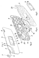
- Fig. 1 shows a sun visor body 1, consisting essentially of a first shell half 2 made of injection molded plastic and a second shell half 3 made of foamed plastic which are set against each other approximately in the central plane of the sun visor body 1 and are coated together with a covering material 4.
- the sun visor body 1 has an upper longitudinal edge 5. At a short distance from the longitudinal edge 5 and essentially parallel to it, there is a folding axis, around which the sun visor body 1 can be moved from a rest position under the vehicle headlining into a use position in front of the windshield.
- the folding axis is formed by the long leg of the L-shaped sun visor axis 6 (whose short leg is supported in the bearing block 7, which in turn is to be fastened to the vehicle body) and the counter bearing pin 8 aligned therewith, the counter bearing pin being detachably in one of the Vehicle body to be fastened to the bracket (not shown) can be locked.
- the sun visor body 1 can also be equipped with a mirror 10 carried by a frame 9. It should be noted that the sun visor body 1 can also be equipped with a lighting device, not shown here, which enables the mirror 10 to be used even in the dark, and that a cover for the mirror in the form of a slide or hinged lid can also be realized.
- the first, injected shell half 2 has stiffening ribs 11 and a framed receiving opening 12 for receiving the frame 9 and the mirror 10.
- the first shell half 2 is designed with a bearing design, generally designated 13, which consists of material projections 15 and webs 16 formed with bearing eyes 14.
- the bearing eyes 14 serve to receive the sun visor axis 6 and the webs 6 for lateral support of the catch spring 17 shown in FIG. 2, the structure of which is described in DE-PS 25 51 633 or EP-B-00 90 157, so that here further explanations can be dispensed with.
- a cover plate 18 shown in FIG. 3 which consists of a plastic injection molded part.
- the cover plate 18 has material approaches 19 with bearing eyes 20 and the material approaches 19 engage between the material approaches 15 and webs 16 of the shell half 2.
- the bearing eyes 14 and 20 together form a pivot bearing receptacle for the sun visor axis 6.
- a pin 21 is also formed on the cover plate 18 which can be clamped in a pin receptacle 22 of the shell half 2.
- the cover plate 18 can also be fixed to the shell half 2 by a clip, adhesive or welded connection.
- the second shell half 3 consists of foam plastic and is preferably formed from polypropylene particle foam.
- the shell half 3 corresponds in its surface dimensions to the shell half 2 and it has at its upper edge 5 a recess 23 for the counter bearing pin 8 (which is formed, for example, in one piece with the shell half 2 but can also be retrofitted as a loose part) and a breakthrough in the surface 24 for the mirror assembly 9, 10.
Landscapes
- Engineering & Computer Science (AREA)
- Mechanical Engineering (AREA)
- Injection Moulding Of Plastics Or The Like (AREA)
- Pivots And Pivotal Connections (AREA)
- Superstructure Of Vehicle (AREA)
Description
- Die Erfindung bezieht sich auf eine Sonnenblende für Fahrzeuge mit einem Sonnenblendenkörper, der aus einer ersten Halbschale aus gespritztem Kunststoff und einer damit verbundenen zweiten Halbschale aus Kunststoffschaum besteht, wobei die gespritzte Halbschale eine Lagerausbildung für die einendige Aufnahme einer Sonnenblendenachse und einer diese klemmenden Feder aufweist.
- Eine Sonnenblende der gattungsgemäßen Art ist unter anderem durch die EP-A- 00 76 174 bekannt geworden. Solche Sonnenblenden werden von den Benutzern geschätzt, weil sie sich bei der Handhabung, bedingt durch die geschäumte Schalenhälfte, besonders griffig anfühlen. Auch kommt die geschäumte Schalenhälfte, die in der Gebrauchslage der Sonnenblende dem Benutzer zugewandt ist, den heutigen, erhöhten Sicherheitsanforderungen entgegen, weil sie bei einem unfallbedingten Aufprall einen Polstereffekt bewirkt. Andererseits ist es bei solchen zweischaligen, hart-weich ausgeführten Sonnenblenden schwierig, eine die Sonnenblendenachse klemmende Feder, die für die Endrastung und Einstellung der Schwenkpositionen des Sonnenblendenkörpers vorzusehen ist, im Sonnenblendenkörper zu integrieren. Beim Gegenstand der EP-A-00 76 174 z.B. wurde eine spritztechnisch schwierige und werkzeugseitig aufwendige Lagerausbildung für die Sonnenblendenachse und Feder vorgesehen und zudem eine neue Federkonzeption gewählt, die nicht als optimal empfunden wird, zumal die Käuferschaft offenbar Federn, wie sie in der DE-PS 25 51 633 oder EP-B- 00 90 157 gezeigt und beschrieben sind, bevorzugt.
- Der vorliegenden Erfindung liegt nun die Aufgabe zugrunde, eine Sonnenblende der eingangs näher erwähnten Art so weiterzubilden, daß sie die Vorteile einer zweischaligen, hart-weichen Ausführung des Sonnenblendenkörpers mit den Vorteilen einer sich in der Praxis hervorragend bewährten Feder der durch die DE-PS 25 51 633 oder EP-B- 00 90 157 bekannt gewordenen Art miteinander vereinigt.
- Diese Aufgabe wird der Erfindung zufolge dadurch gelöst, daß die Lagerausbildung auf der der geschäumten Halbschale zugewandten Seite unter positionierter Festlegung der in der Lagerausbildung angeordneten Feder, durch eine Abdeckplatte verschlossen ist.
- Die erfindungsgemäß vorgeschlagene Lösung trägt dem Umstand Rechnung, daß die weichelastische Eigenschaft der geschäumten Halbschale nicht geeignet ist, einer Taumelbewegung der Feder beim Verschwenken der Sonnenblende entgegenzuwirken, sofern die geschäumte Halbschale unmittelbar zur Abstützung der Feder herangezogen wird. Hingegen ist eine Abdeckplatte aus hartem, vorzugsweise spritzgegossenem Kunststoffmaterial, die an der gespritzten Halbschale befestigt ist, sehr wohl in der Lage, eine Feder in Verbindung mit der gespritzten Halbschale, nach Art eines Aufnahmenestes zu haltern und zu sichern. Versuche und Berechnungen haben ergeben, daß die Abdeckplatte sich derart einfach und kostengünstig herstellen und montieren läßt, daß eine damit ausgerüstete Sonnenblende nur vernachläßigbar gering verteuert, qualitätsmäßig hingegen wesentlich verbessert wird.
- Gemäß einer Ausgestaltung der Erfindung kann vorgesehen sein, daß die Lageraufnahme einander beabstandete Materialansätze mit Lageraugen für die Sonnenblendenachse aufweist, die sowohl an der gespritzten Halbschale als auch an der Abdeckplatte angeformt sind und in verzahnter Anordnung ineinander greifen. Damit ergibt sich schon eine wesentliche Halterung der Abdeckplatte durch die die Lageraugen durchsetzende Sonnenblendeachse. Zusätzlich oder alternativ kann vorgesehen sein, daß die Abdeckplatte an der gespritzten Halbschale durch eine Klemm-, Klips-, Klebe- oder Schweißverbindung festlegbar ist.
- Schließlich besteht eine Weiterbildung der Erfindung noch darin, daß die Lagerausbildung mit an der gespritzten Halbschale und/oder Abdeckplatte angeformten Stegen zur Festlegung der Feder in Achsrichtung der Sonnenblendenachse ausgebildet ist.
- Ein Ausführungsbeispiel der Erfindung wird nachfolgend anhand der Zeichnung näher erläutert. Es zeigen
- Fig. 1 eine perspektivische Ansicht der Sonnenblende mit separat dargestellter Sonnenblendenachse nebst Lagerböckchen,
- Fig. 2 eine erste, gespritzte Halbschale des Sonnenblendenkörpers,
- Fig 3 eine Einzelheit der Erfindung,
- Fig. 4 eine zweite, geschäumte Halbschale des Sonnenblendenkörpers und
- Fig. 5 einen die Sonnenblende vervollständigenden, in einem Rahmen eingefaßten Spiegel.
- Fig. 1 zeigt einen Sonnenblendenkörper 1, im wesentlichen bestehend aus einer ersten Schalenhälfte 2 aus gespritztem Kunststoff und einer zweiten Schalenhälfte 3 aus geschäumten Kunststoff die etwa in der Mittelebene des Sonnenblendenkörpers 1 gegeneinander gesetzt und gemeinsam mit einem Umhüllungsmaterial 4 ummantelt sind. Der Sonnenblendenkörper 1 weist eine obere Längskante 5 auf. Mit geringem Abstand von der Längskante 5 und im wesentlichen parallel dazu, verläuft eine Klappachse, um die herum der Sonnenblendenkörper 1 aus einer Ruhelage unter dem Fahrzeughimmel in eine Gebrauchslage vor der Windschutzscheibe bewegt werden kann. Die Klappachse wird durch den langen Schenkel der L-förmig ausgebildeten Sonnenblendenachse 6 (deren kurzer Schenkel im Lagerböckchen 7, das seinerseits an der Fahrzeugkarosserie zu befestigen ist, gelagert ist) und dem damit fluchtenden Gegenlagerstift 8 gebildet, wobei der Gegenlagerstift lösbar in einem an der Fahrzeugkarosserie zu befestigenden Gegenlagerböckchen (nicht gezeigt) einrastbar ist. Fig. 1 zeigt weiterhin, daß der Sonnenblendenkörper 1 auch mit einem von einem Rahmen 9 getragenen Spiegel 10 ausgerüstet sein kann. Es sei bemerkt, daß der Sonnenblendenkörper 1 ferner mit einer, hier nicht dargestellten Beleuchtungseinrichtung, die eine Benutzung des Spiegels 10 auch bei Dunkelheit ermöglicht, ausgerüstet sein kann und daß auch eine Abdeckung für den Spiegel in Form eines Schiebers oder Klappdeckels realisierbar ist.
- Wie Fig. 2 zeigt, weist die erste, gespritzte Schalenhälfte 2 Versteifungsrippen 11 und eine umrahmte Aufnahmeöffnung 12 für die Aufnahme des Rahmens 9 und des Spiegels 10 auf. Insbesondere ist die erste Schalenhälfte 2 mit einer, insgesamt mit 13 bezeichneten Lagerausbildung ausgeführt, die aus mit Lageraugen 14 ausgebildeten Materialansätzen 15 und Stegen 16 besteht. Die Lageraugen 14 dienen zur Aufnahme der Sonnenblendenachse 6 und die Stege 6 zur seitlichen Abstützung der in Fig. 2 mit dargestellten Rastfeder 17, deren Aufbau in der DE-PS 25 51 633 oder EP-B- 00 90 157 beschrieben ist, so daß hier auf weitere Erläuterungen verzichtet werden kann. Nach dem Einsetzen der U-förmigen Rastfeder 17 in den durch die Stege 16 gebildeten Aufnahmeraum wird dieselbe in Richtung zur Schalenhälfte 3 hin gesichert, wozu eine in Fig. 3 dargestellte Abdeckplatte 18 vorgesehen ist, die aus einem Kunststoffspritzgußteil besteht. Die Abdeckplatte 18 weist Materialansätze 19 mit Lageraugen 20 auf und die Materialansätze 19 greifen zwischen die Materialansätze 15 und Stege 16 der Schalenhälfte 2. Die Lageraugen 14 und 20 bilden gemeinsam eine Drehlageraufnahme für die Sonnenblendenachse 6. An der Abdeckplatte 18 ist weiterhin ein Zapfen 21 angeformt, der in eine Zapfenaufnahme 22 der Schalenhälfte 2 einklemmbar ist. Die Abdeckplatte 18 kann auch durch eine Klips-, Klebe- oder Schweißverbindung an der Schalenhälfte 2 festgelegt sein. Wesentlich ist, daß die Lagerausbildung 13 ein die Feder 17 allseitig abstützendes Nest bildet,und zwar in Verbindung mit der Abdeckplatte 18. Die zweite Schalenhälfte 3 besteht aus Schaumkunststoff und ist vorzugsweise aus Polypropylen-Partikelschaum gebildet. Die Schalenhälfte 3 entspricht in ihren Flächenabmessungen der Schalenhälfte 2 und sie weist an ihrem oberen Rand 5 eine Aussparung 23 für den Gegenlagerstift 8 (der z.B. einstückig mit der schalenhälfte 2 ausgebildet ist aber auch als Losteil nachträglich montiert werden kann) und in der Fläche einen Durchbruch 24 für die Spiegelbaueinheit 9, 10 auf.
Claims (4)
- Sonnenblende für Fahrzeuge, mit einem Sonnenblendenkörper (1), der aus einer ersten Halbschale (2) aus gespritztem Kunststoff und einer damit verbundenen zweiten Halbschale (3) aus Kunststoffschaum besteht, wobei die gespritzte Halbschale (2) eine Lagerausbildung (13) für die einendige Aufnahme einer Sonnenblendenachse (6) und einer diese klemmenden Feder (17) aufweist, dadurch gekennzeichnet, daß die Lagerausbildung (13) auf der, der geschäumten Halbschale (3) zugewandten Seite, unter positionierter Festlegung der in der Lagerausbildung (13) angeordneten Feder (17), durch eine Abdeckplatte (18) verschlossen ist.
- Sonnenblende nach Anspruch 1, dadurch gekennzeichnet, daß die Lagerausbildung (13) einander beabstandete Materialansätze (15, 19) mit Lageraugen (14, 20) für die Sonnenblendenachse (6) aufweist, die sowohl an der gespritzten Halbschale (2) als auch an der Abdeckplatte (18) angeformt sind und in verzahnter Anordnung ineinandergreifen.
- Sonnenblende nach Anspruch 1 oder 2, dadurch gekennzeichnet, daß die Abdeckplatte (18) an der gespritzten Halbschale (2) durch eine Klemm-, Klips-, Klebe- oder Schweißverbindung festgelegt ist.
- Sonnenblende nach einem oder mehreren der Ansprüche 1 bis 3, dadurch gekennzeichnet, daß die Lagerausbildung (13) mit an der gespritzten Halbschale (2) und/oder Abdeckplatte (18) angeformten Stegen (16) zur Festlegung der Feder (17) in Achsrichtung der Sonnenblendenachse (6) ausgebildet ist.
Applications Claiming Priority (2)
| Application Number | Priority Date | Filing Date | Title |
|---|---|---|---|
| DE3919021 | 1989-06-10 | ||
| DE3919021A DE3919021A1 (de) | 1989-06-10 | 1989-06-10 | Sonnenblende fuer fahrzeuge |
Publications (2)
| Publication Number | Publication Date |
|---|---|
| EP0402586A1 EP0402586A1 (de) | 1990-12-19 |
| EP0402586B1 true EP0402586B1 (de) | 1993-02-03 |
Family
ID=6382508
Family Applications (1)
| Application Number | Title | Priority Date | Filing Date |
|---|---|---|---|
| EP90106480A Expired - Lifetime EP0402586B1 (de) | 1989-06-10 | 1990-04-05 | Sonnenblende für Fahrzeuge |
Country Status (3)
| Country | Link |
|---|---|
| EP (1) | EP0402586B1 (de) |
| DE (2) | DE3919021A1 (de) |
| ES (1) | ES2038461T3 (de) |
Families Citing this family (9)
| Publication number | Priority date | Publication date | Assignee | Title |
|---|---|---|---|---|
| DE4107696A1 (de) * | 1991-03-09 | 1992-09-10 | Happich Gmbh Gebr | Sonnenblende fuer fahrzeuge |
| ES2036917B1 (es) * | 1991-06-04 | 1994-06-01 | Ind Techno Matic Sa | Dispositivo de fijacion de espejos de cortesia de viseras parasol. |
| DE4234760A1 (de) * | 1992-10-15 | 1994-04-21 | Happich Gmbh Gebr | Sonnenschutzblende |
| DE19523067A1 (de) * | 1994-08-02 | 1996-02-08 | Happich Gmbh Gebr | Sonnenblende für Fahrzeuge |
| DE19648552A1 (de) * | 1996-11-23 | 1998-05-28 | Happich Gmbh Gebr | Sonnenblende für Fahrzeuge |
| FR2766770B1 (fr) * | 1997-08-04 | 1999-10-22 | Rockwell Lvs France | Pare-soleil comportant une armature reticulee |
| DE10025112B4 (de) * | 2000-05-20 | 2006-06-08 | Johnson Controls Interiors Gmbh & Co. Kg | Sonnenblende für Fahrzeuge |
| JP2003252048A (ja) * | 2002-03-04 | 2003-09-09 | Nishikawa Kasei Co Ltd | 車両用サンバイザ |
| DE102010047044A1 (de) * | 2010-07-27 | 2012-02-02 | Johnson Controls Interiors Gmbh & Co. Kg | Sonnenblende und Verfahren zu deren Montage |
Family Cites Families (7)
| Publication number | Priority date | Publication date | Assignee | Title |
|---|---|---|---|---|
| DE2551633C2 (de) * | 1975-11-18 | 1979-02-15 | Gebr. Happich Gmbh, 5600 Wuppertal | Lager für einen Sonnenblendenkörper, insbesondere für Fahrzeugsonnenblenden |
| DE3005824A1 (de) * | 1980-02-16 | 1981-09-03 | Gebr. Happich Gmbh, 5600 Wuppertal | Sonnenblende fuer fahrzeuge |
| DE8013676U1 (de) * | 1980-05-21 | 1980-08-21 | Zipperle, Wolfgang, 7140 Ludwigsburg | Sonnenblende fuer kraftfahrzeuge |
| FR2513578A1 (fr) * | 1981-09-28 | 1983-04-01 | Mecanismes Comp Ind De | Pare-soleil, notamment pour vehicule automobile |
| DE8208831U1 (de) * | 1982-03-27 | 1982-07-22 | Fa. A. Raymond, 7850 Lörrach | Lager fuer sonnenblendenkoerper |
| DE3601761C1 (de) * | 1986-01-22 | 1987-04-30 | Happich Gmbh Gebr | Sonnenblende fuer Fahrzeuge |
| DE3701760A1 (de) * | 1987-01-22 | 1988-08-04 | Happich Gmbh Gebr | Sonnenblende fuer fahrzeuge |
-
1989
- 1989-06-10 DE DE3919021A patent/DE3919021A1/de not_active Withdrawn
-
1990
- 1990-04-05 EP EP90106480A patent/EP0402586B1/de not_active Expired - Lifetime
- 1990-04-05 DE DE9090106480T patent/DE59000836D1/de not_active Expired - Fee Related
- 1990-04-05 ES ES199090106480T patent/ES2038461T3/es not_active Expired - Lifetime
Also Published As
| Publication number | Publication date |
|---|---|
| DE3919021A1 (de) | 1990-12-13 |
| ES2038461T3 (es) | 1993-07-16 |
| DE59000836D1 (de) | 1993-03-18 |
| EP0402586A1 (de) | 1990-12-19 |
Similar Documents
| Publication | Publication Date | Title |
|---|---|---|
| DE69800304T2 (de) | Kühlergrill- Anordnung | |
| EP0402586B1 (de) | Sonnenblende für Fahrzeuge | |
| EP1063146A1 (de) | Fahrzeuglenkrad | |
| EP0157919A2 (de) | Sonnenblende, insbesondere für Fahrzeuge | |
| DE2727394A1 (de) | Deckel, insbesondere handschuhkastendeckel fuer kraftfahrzeuge | |
| DE69808398T2 (de) | Fahrzeugspiegel | |
| DE3508226A1 (de) | Fahrzeug mit einem aussenspiegel | |
| EP0129793B1 (de) | Sonnenblende für Fahrzeuge | |
| DE3226445C2 (de) | An einem Rahmen eines Motorrads od. dgl. befestigbares Tragelement zur Aufnahme eines Motorradkoffers oder ähnlichem | |
| DE3700854A1 (de) | Energieabsorbierende einrichtung an einer stossstange von kraftfahrzeugen | |
| DE4102823A1 (de) | Fahrschemel | |
| DE3004181C2 (de) | Halter zum Befestigen einer Stoßstange an einem Fahrzeug | |
| DE19731535A1 (de) | Sonnenblende für Fahrzeuge | |
| DE3032392C2 (de) | Außenspiegel für Fahrzeuge | |
| DE69006703T2 (de) | Scharnier für eine Sonnenblende eines Kraftfahrzeuges. | |
| DE7930613U1 (de) | Sonnenblende fuer kraftfahrzeuge | |
| DE1906915A1 (de) | Kunststofflagerteil | |
| EP0496964B1 (de) | Sonnenblende für Fahrzeuge | |
| DE2755836C2 (de) | Kraftfahrzeugausrüstungsteil | |
| EP0504619B1 (de) | Waschmaschine | |
| DE102004032379A1 (de) | Windstopeinrichtung | |
| DE3916625A1 (de) | Sonnenblende fuer fahrzeuge | |
| DE2541546A1 (de) | Sonnenblende fuer kraftfahrzeuge | |
| DE4234760A1 (de) | Sonnenschutzblende | |
| DE29902601U1 (de) | Tasche für den Innenraum von Fahrzeugen |
Legal Events
| Date | Code | Title | Description |
|---|---|---|---|
| PUAI | Public reference made under article 153(3) epc to a published international application that has entered the european phase |
Free format text: ORIGINAL CODE: 0009012 |
|
| AK | Designated contracting states |
Kind code of ref document: A1 Designated state(s): DE ES FR GB IT SE |
|
| 17P | Request for examination filed |
Effective date: 19900925 |
|
| 17Q | First examination report despatched |
Effective date: 19920415 |
|
| GRAA | (expected) grant |
Free format text: ORIGINAL CODE: 0009210 |
|
| AK | Designated contracting states |
Kind code of ref document: B1 Designated state(s): DE ES FR GB IT SE |
|
| ITF | It: translation for a ep patent filed | ||
| GBT | Gb: translation of ep patent filed (gb section 77(6)(a)/1977) |
Effective date: 19930215 |
|
| REF | Corresponds to: |
Ref document number: 59000836 Country of ref document: DE Date of ref document: 19930318 |
|
| ET | Fr: translation filed | ||
| REG | Reference to a national code |
Ref country code: ES Ref legal event code: FG2A Ref document number: 2038461 Country of ref document: ES Kind code of ref document: T3 |
|
| PLBE | No opposition filed within time limit |
Free format text: ORIGINAL CODE: 0009261 |
|
| STAA | Information on the status of an ep patent application or granted ep patent |
Free format text: STATUS: NO OPPOSITION FILED WITHIN TIME LIMIT |
|
| 26N | No opposition filed | ||
| EAL | Se: european patent in force in sweden |
Ref document number: 90106480.8 |
|
| REG | Reference to a national code |
Ref country code: ES Ref legal event code: PC2A |
|
| REG | Reference to a national code |
Ref country code: FR Ref legal event code: CD |
|
| PGFP | Annual fee paid to national office [announced via postgrant information from national office to epo] |
Ref country code: SE Payment date: 19980319 Year of fee payment: 9 |
|
| PGFP | Annual fee paid to national office [announced via postgrant information from national office to epo] |
Ref country code: GB Payment date: 19980320 Year of fee payment: 9 |
|
| PG25 | Lapsed in a contracting state [announced via postgrant information from national office to epo] |
Ref country code: GB Free format text: LAPSE BECAUSE OF NON-PAYMENT OF DUE FEES Effective date: 19990405 |
|
| PG25 | Lapsed in a contracting state [announced via postgrant information from national office to epo] |
Ref country code: SE Free format text: LAPSE BECAUSE OF NON-PAYMENT OF DUE FEES Effective date: 19990406 |
|
| PGFP | Annual fee paid to national office [announced via postgrant information from national office to epo] |
Ref country code: ES Payment date: 19990408 Year of fee payment: 10 |
|
| GBPC | Gb: european patent ceased through non-payment of renewal fee |
Effective date: 19990405 |
|
| EUG | Se: european patent has lapsed |
Ref document number: 90106480.8 |
|
| PGFP | Annual fee paid to national office [announced via postgrant information from national office to epo] |
Ref country code: FR Payment date: 20000313 Year of fee payment: 11 |
|
| PG25 | Lapsed in a contracting state [announced via postgrant information from national office to epo] |
Ref country code: ES Free format text: THE PATENT HAS BEEN ANNULLED BY A DECISION OF A NATIONAL AUTHORITY Effective date: 20000406 |
|
| PGFP | Annual fee paid to national office [announced via postgrant information from national office to epo] |
Ref country code: DE Payment date: 20000407 Year of fee payment: 11 |
|
| PG25 | Lapsed in a contracting state [announced via postgrant information from national office to epo] |
Ref country code: FR Free format text: THE PATENT HAS BEEN ANNULLED BY A DECISION OF A NATIONAL AUTHORITY Effective date: 20010430 |
|
| PG25 | Lapsed in a contracting state [announced via postgrant information from national office to epo] |
Ref country code: DE Free format text: LAPSE BECAUSE OF NON-PAYMENT OF DUE FEES Effective date: 20020201 |
|
| REG | Reference to a national code |
Ref country code: FR Ref legal event code: ST |
|
| REG | Reference to a national code |
Ref country code: ES Ref legal event code: FD2A Effective date: 20020204 |
|
| PG25 | Lapsed in a contracting state [announced via postgrant information from national office to epo] |
Ref country code: IT Free format text: LAPSE BECAUSE OF NON-PAYMENT OF DUE FEES;WARNING: LAPSES OF ITALIAN PATENTS WITH EFFECTIVE DATE BEFORE 2007 MAY HAVE OCCURRED AT ANY TIME BEFORE 2007. THE CORRECT EFFECTIVE DATE MAY BE DIFFERENT FROM THE ONE RECORDED. Effective date: 20050405 |