EP0401615A1 - Turbolader - Google Patents
Turbolader Download PDFInfo
- Publication number
- EP0401615A1 EP0401615A1 EP90109942A EP90109942A EP0401615A1 EP 0401615 A1 EP0401615 A1 EP 0401615A1 EP 90109942 A EP90109942 A EP 90109942A EP 90109942 A EP90109942 A EP 90109942A EP 0401615 A1 EP0401615 A1 EP 0401615A1
- Authority
- EP
- European Patent Office
- Prior art keywords
- support
- turbocharger
- wastegate valve
- arm
- valve members
- Prior art date
- Legal status (The legal status is an assumption and is not a legal conclusion. Google has not performed a legal analysis and makes no representation as to the accuracy of the status listed.)
- Granted
Links
Images

Classifications
-
- F—MECHANICAL ENGINEERING; LIGHTING; HEATING; WEAPONS; BLASTING
- F02—COMBUSTION ENGINES; HOT-GAS OR COMBUSTION-PRODUCT ENGINE PLANTS
- F02B—INTERNAL-COMBUSTION PISTON ENGINES; COMBUSTION ENGINES IN GENERAL
- F02B37/00—Engines characterised by provision of pumps driven at least for part of the time by exhaust
- F02B37/12—Control of the pumps
- F02B37/18—Control of the pumps by bypassing exhaust from the inlet to the outlet of turbine or to the atmosphere
- F02B37/183—Arrangements of bypass valves or actuators therefor
-
- F—MECHANICAL ENGINEERING; LIGHTING; HEATING; WEAPONS; BLASTING
- F02—COMBUSTION ENGINES; HOT-GAS OR COMBUSTION-PRODUCT ENGINE PLANTS
- F02B—INTERNAL-COMBUSTION PISTON ENGINES; COMBUSTION ENGINES IN GENERAL
- F02B37/00—Engines characterised by provision of pumps driven at least for part of the time by exhaust
- F02B37/12—Control of the pumps
-
- F—MECHANICAL ENGINEERING; LIGHTING; HEATING; WEAPONS; BLASTING
- F01—MACHINES OR ENGINES IN GENERAL; ENGINE PLANTS IN GENERAL; STEAM ENGINES
- F01D—NON-POSITIVE DISPLACEMENT MACHINES OR ENGINES, e.g. STEAM TURBINES
- F01D17/00—Regulating or controlling by varying flow
- F01D17/10—Final actuators
- F01D17/105—Final actuators by passing part of the fluid
-
- F—MECHANICAL ENGINEERING; LIGHTING; HEATING; WEAPONS; BLASTING
- F02—COMBUSTION ENGINES; HOT-GAS OR COMBUSTION-PRODUCT ENGINE PLANTS
- F02B—INTERNAL-COMBUSTION PISTON ENGINES; COMBUSTION ENGINES IN GENERAL
- F02B37/00—Engines characterised by provision of pumps driven at least for part of the time by exhaust
- F02B37/02—Gas passages between engine outlet and pump drive, e.g. reservoirs
- F02B37/025—Multiple scrolls or multiple gas passages guiding the gas to the pump drive
-
- F—MECHANICAL ENGINEERING; LIGHTING; HEATING; WEAPONS; BLASTING
- F02—COMBUSTION ENGINES; HOT-GAS OR COMBUSTION-PRODUCT ENGINE PLANTS
- F02B—INTERNAL-COMBUSTION PISTON ENGINES; COMBUSTION ENGINES IN GENERAL
- F02B37/00—Engines characterised by provision of pumps driven at least for part of the time by exhaust
- F02B37/12—Control of the pumps
- F02B37/18—Control of the pumps by bypassing exhaust from the inlet to the outlet of turbine or to the atmosphere
- F02B37/183—Arrangements of bypass valves or actuators therefor
- F02B37/186—Arrangements of actuators or linkage for bypass valves
-
- Y—GENERAL TAGGING OF NEW TECHNOLOGICAL DEVELOPMENTS; GENERAL TAGGING OF CROSS-SECTIONAL TECHNOLOGIES SPANNING OVER SEVERAL SECTIONS OF THE IPC; TECHNICAL SUBJECTS COVERED BY FORMER USPC CROSS-REFERENCE ART COLLECTIONS [XRACs] AND DIGESTS
- Y02—TECHNOLOGIES OR APPLICATIONS FOR MITIGATION OR ADAPTATION AGAINST CLIMATE CHANGE
- Y02T—CLIMATE CHANGE MITIGATION TECHNOLOGIES RELATED TO TRANSPORTATION
- Y02T10/00—Road transport of goods or passengers
- Y02T10/10—Internal combustion engine [ICE] based vehicles
- Y02T10/12—Improving ICE efficiencies
Definitions
- This invention relates to an exhaust gas bypass and wastegate valve arrangement for exhaust gas driven turbochargers and, more specifically, to a wastegate valve which opens and closes a bypass outlet port.
- a turbocharger is used to increase the pressure level of the intake combustion air of an internal combustion engine, and is powered by engine exhaust gas pressure.
- the level to which the pressure of the intake air is increased during high speed and high load operating ranges of the engine is prevented from becoming excessive to prevent damage to the engine and turbocharger by opening a wastegate valve which normally closes the bypass gas outlet port. Accordingly, when the exhaust gas pressure has exceeded a predetermined value, the wastegate valve is opened thereby discharging the exhaust gas to the exterior.
- turbochargers used on engines with two banks of cylinders, it has been found extremely effective to maintain separate exhaust gas inlet paths by means of a bulkhead in order that separate impulses of the exhaust gases will be transmitted to the turbine wheel.
- Such turbochargers having divided exhaust gas inlet paths require separate bypass gas outlet ports controlled by a dual wastegate valve mechanism.
- valve members are secured directly to the arm member so as to cause another problem in that even a slight distortion of the arm member results in exhaust gas flowing through the respective outlet port when the outlet port should be closed and eventually results in incapability of transmitting the pressure impulses of the exhaust gas to the turbine wheel at high efficiency.
- the valve members are coupled to the arm member through a pin for allowing limited displacement of the valve members to accommodate any distortion in the arm member or any differential in valve seat height so that the bypass gas outlet ports are opened and closed concurrently.
- this arrangement causes another problem in that excessive movement is likely to occur between the arm member and the pin holding the valve members on the arm member so as to cause a risk of opening one or both of the valve members before the intake pressure becomes excessive. Accordingly, the pressure impulse of the exhaust gas is not transmitted to the turbine wheel at high efficiency.
- An object of the present invention is, therefore, to provide an exhaust gas wastegate valve and bypass arrangement for a turbocharger which is capable of maintaining the wastegate valve members tightly on their valve seats even if the arm member and valve seats are distorted or if excessive tolerances are present between the respective bypass gas outlet ports so that pressure impulses of the exhaust gases are transmitted to the turbine wheel highly efficiently.
- an exhaust gas bypass and wastegate valve arrangement for a turbocharger comprising a pair of divided gas inlet paths for feeding exhaust gases from an internal combustion engine to a turbine wheel, a bypass passage communicating with the gas inlet paths through a pair of bypass gas outlet ports, a pair of wastegate valve members seatable on valve seats at the bypass gas outlet ports, a valve support carrying the valve members through mounting members mounted to the support at a symmetrical position with respect thereto, and an arm member supporting the valve support and permitting a slight shifting of the valve support when the wastegate valve members are closed.
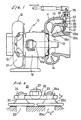
- a turbocharger 10 includes a turbine section 11 and a compressor section 12.
- the turbine section 11 includes a turbine wheel 13 rotated by exhaust gases, and a turbine housing 14 in which the turbine wheel 13 is housed.
- the compressor section 12 includes a compressor wheel 15 coupled through a coupling shaft 10a to the turbine wheel 13 for rotation by the turbine wheel 13.
- a compressor housing 17 is provided for housing the compressor wheel 15, and a center housing 16 is interposed between the compressor and turbine housings.
- the turbine housing 14 defines separated inlet paths 18 and 18a for the exhaust gas of the internal combustion engine.
- a bulkhead 19 separates paths 18 and 18a so that the exhaust gases will be fed to the turbine wheel 13 in two streams for effectively transmitting the pressure impulses of the exhaust gas to the turbine wheel.
- the divided gas inlet paths 18 and 18a are provided for communication to atmosphere through a pair of bypass gas outlet ports 20 and 20a and a bypass passage 21.
- a pair of wastegate valve members 22 and 22a are provided for opening and closing the bypass gas outlet ports 20 and 20a.
- the pair of wastegate valve members 22 and 22a are mounted on a valve support 23 symmetrically with respect to the center of the support.
- a pair of mounting members 24 and 24a extend through the valve support 23 and secure wastegate valve members 22 and 22a with clearance to the support 23 for allowing the wastegate valve members 22 and 22a to shift slightly as they are opened and closed.
- An arm member 25 is coupled at its tip end 26 to the center of support 23 through a mounting member 27.
- the tip end 26 of the arm member 25 is formed in a semicircular shape in section and is engaged on its arcuate side to the top surface of the support 23 so that the support 23 can swing relative to arm 25 as the wastegate valve members are opened and closed.
- the mounting member 27 for the arm member 25 is provided with an abutment engaging the valve supporter 23 and bent at two extended ends into a downward L-shape (see in particular Figure 3) to engage both side edges of the support 23 so that any rotation of this supporter 23 about the mounting member 27 in the same plane of the arm 25 will be restrained.
- the arm member 25 extends through a flexible bushing in the housing and is coupled to a control arm 28 which per se is interlocked with a control means (not shown) of any known arrangement, so that the wastegate valve actuating system as in the above will be actuated.
- the wastegate valve members 22 and 22a are respectively made slightly shiftable with respect to the valve supporter 23 in the direction shown by an arrow x in Figure 2 and the valve support 23 in turn is swingable with respect to the arm member 25 as shown by an arrow y so that, upon seating of the respective wastegate valve members 22 and 22a onto the valve seats at the bypass gas outlet ports 20 and 20a, the wastegate valve members 22 and 22a will shift independently in a direction closing the ports even in the presence of any difference in height between the valve seats, or any pressure difference between the outlet ports 20 and 20a, and the wastegate valve members 22 and 22a are seated tightly substantially simultaneously.
- the semicircular tip end 26 of the arm member 25 causes a centering action so that the bypass valves 22 and 22a are closed against their valve seats reliably.
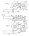
- FIGS. 4 and 5 there is shown another embodiment of the present invention, in which an arm member 125 is mounted onto a support 1223 through a flattened surface of a semicircular-shaped tip end 126 of the arm member 125.
- An overlaying strip 129 having an arcuately bent section 128 to conform to the surface of the tip end 126 is provided on the support 123 and extends across the tip end 126 of the arm member 125.
- Mounting members 124 and 124a are mounted on the support 123 and pass through both the support 123 and the overlaying strip 129, and wastegate valve members 122 and 122a are mounted to these mounting members 124 and 124a.
- both end parts of the overlaying strip 129 may be rigidly secured to the support 123 by means of spot welding.
- the tip end 126 of the arm member 125 is in contact with the arcuate portion 128 of the overlaying strip 129 so that the support 123 and wastegate valve members 122 and 122a will be swingable with respect to the arm member 125 and the valves 122 and 122a can be simultaneously seated smoothly on the valve seats in the same manner as in the foregoing embodiment.
- the tip end 126 includes portions facing the side edges of the support 123 so as to lockingly engage these side edges, so that the valve supporter 123 can be prevented from being rotated in the plane of the arm 125 in the same manner as in the foregoing embodiment.
- a pair of wastegate valve members 222 and 222a are supported by support 223, which is rectangularly shaped in plan view, at symmetrical positions with respect to the center of support 223.
- the support 223 has holes 224 and 224a, and a pair of mounting members 225 and 225a are passed through holes 224 and 224a.
- the mounting members 225 and 225a are coupled to the wastegate valve members 222 and 222a.
- the holes 224 and 224a are of a diameter allowing the mounting members 225 and 225a and accordingly the bypass valves 222 and 22a to pivot by an angle 0 ⁇ 1 with respect to the center line of each of the wastegate valve members 222 and 222a.
- a holder 227 formed at the tip end of arm member 226 is coupled so as to allow the support 223 to be swingable with respect to the holder 227 by an angle 0 ⁇ 2, which is smaller than the above angle 0 ⁇ 1. Accordingly, the holder 227 is shaped to be substantially identical to the rectangular shape of the support 223, and a hole 229 extends through the center of holder 227 for receiving a mounting member 228.
- the bottom surface of the holder 227 is formed to have tapered faces 230 and 230a with the thickness gradually reduced from the center of the holder to each of the opposite end portions, while the diameter of the holes 229 allow the mounting member 228 and eventually the support 223 to swing, the support 223 thus being swingable by the angle 0 ⁇ 2 with respect to the holder 227.
- relief holes 231 and 231a are provided into which head portions of the mounting member 25 and 25a can freely engage.
- the mounting member 228 be provided with a restraining means extended in width direction of the holder section 27 and bent at extended ends downward into an L-shape so that such extended restraining means will engage lockingly both side edges of the support 23 so as to prevent it from rotating about the mounting member 23, and the center in the plane of the arm.
- the means for restraining the rotation of the support 23 may be of any other form so long as the valve supporter 23 is swingable by the smaller angle of 0 ⁇ 2.
- the wastegate valve members 222 and 222a are swingable on the bottom surface of the support 223 by the relatively larger angle 0 ⁇ 1 in the direction shown by an arrow x in Figure 8, and the support 223 and eventually the wastegate valve members 222 and 222a pivot through the angle 0 ⁇ 2, which is smaller than the foregoing angle 0 ⁇ 1 in the direction shown by an arrow y in Figure 8, so that the wastegate valve members 222 and 222a can be made to tightly seat on the valves seats simultaneously, even in an event where the gas outlet ports 220 and 220a are distorted at the valve seats, of when one of the wastegate valve members 222 and 222a is made to open to regulate pressure due to a difference in the pressure at the outlet ports 220 and 220a.
- the wastegate valve members 222 and 222a are shiftable in two directions and the swingable angle is set in the valve opening and closing directions, i.e., in the arrow y directions, so that any bumpy movement between the bypass valves 222 and 222a and the arm member is reduced.
Applications Claiming Priority (4)
| Application Number | Priority Date | Filing Date | Title |
|---|---|---|---|
| JP1989066847U JPH036026U (de) | 1989-06-09 | 1989-06-09 | |
| JP66847/89 | 1989-06-09 | ||
| JP66846/89 | 1989-06-09 | ||
| JP1989066846U JPH035936U (de) | 1989-06-09 | 1989-06-09 |
Publications (2)
| Publication Number | Publication Date |
|---|---|
| EP0401615A1 true EP0401615A1 (de) | 1990-12-12 |
| EP0401615B1 EP0401615B1 (de) | 1994-12-28 |
Family
ID=26408047
Family Applications (1)
| Application Number | Title | Priority Date | Filing Date |
|---|---|---|---|
| EP90109942A Expired - Lifetime EP0401615B1 (de) | 1989-06-09 | 1990-05-25 | Turbolader |
Country Status (5)
| Country | Link |
|---|---|
| US (1) | US5046317A (de) |
| EP (1) | EP0401615B1 (de) |
| KR (1) | KR960003677B1 (de) |
| DE (1) | DE69015449T2 (de) |
| ES (1) | ES2068944T3 (de) |
Cited By (10)
| Publication number | Priority date | Publication date | Assignee | Title |
|---|---|---|---|---|
| DE19853392A1 (de) * | 1998-11-19 | 2000-05-31 | Man Nutzfahrzeuge Ag | Waste-Gate-Ventil für einen zweiflutigen Abgasturbolader |
| WO2004053310A1 (de) * | 2002-12-12 | 2004-06-24 | Daimlerchrysler Ag | Brennkraftmaschine mit einem abgasturbolader |
| WO2007002520A1 (en) * | 2005-06-28 | 2007-01-04 | Honeywell International, Inc. | Wastegate valve and associated method |
| WO2011137004A3 (en) * | 2010-04-30 | 2012-03-01 | Honeywell International Inc. | Turbocharger with turbine nozzle vanes and an annular rotary bypass valve |
| EP2708717A1 (de) * | 2012-09-13 | 2014-03-19 | Honeywell International Inc. | Turbinen-Wastegate |
| US8904785B2 (en) | 2012-09-13 | 2014-12-09 | Honeywell International Inc. | Turbine wastegate |
| CN107725176A (zh) * | 2016-08-10 | 2018-02-23 | 通用汽车环球科技运作有限责任公司 | 具有双废气门阀的涡轮增压器 |
| WO2019122836A1 (en) * | 2017-12-19 | 2019-06-27 | Cummins Ltd | Wastegate assembly for turbine |
| WO2019122853A1 (en) * | 2017-12-19 | 2019-06-27 | Cummins Ltd | Wastegate for turbine |
| EP3670848A1 (de) * | 2018-12-20 | 2020-06-24 | Borgwarner Inc. | Turbinengehäuse eines turboladers |
Families Citing this family (47)
| Publication number | Priority date | Publication date | Assignee | Title |
|---|---|---|---|---|
| US5746058A (en) * | 1996-03-11 | 1998-05-05 | Gits Manufacturing Company | Adjustable actuator for a turbocharger |
| DE19618160C2 (de) * | 1996-05-07 | 1999-10-21 | Daimler Chrysler Ag | Abgasturbolader für eine Brennkraftmaschine |
| US5996348A (en) | 1997-03-17 | 1999-12-07 | Alliedsignal Inc. | Dual poppet wastegate with dual coaxial shafts |
| SE519433C2 (sv) * | 1997-07-07 | 2003-02-25 | Scania Cv Ab | Hus för turboöverladdare för förbränningsmotor samt turboöverladdare |
| US6109167A (en) * | 1998-06-04 | 2000-08-29 | Gits Manufacturing Company | Actuator with axially movable O-rings between piston and housing |
| US6880572B2 (en) * | 2002-04-15 | 2005-04-19 | Jenara Enterprises Ltd. | Exhaust gas control valve, apparatus and method of controlling exhaust gas flow |
| US6748848B1 (en) | 2002-12-11 | 2004-06-15 | Gits Manufacturing Company, Llc | Waste gate valve actuator |
| US6941755B2 (en) * | 2003-10-28 | 2005-09-13 | Daimlerchrysler Corporation | Integrated bypass and variable geometry configuration for an exhaust gas turbocharger |
| US7269950B2 (en) * | 2004-05-05 | 2007-09-18 | Precision Industries, Inc. | Staged turbocharger |
| DE202005008606U1 (de) * | 2005-06-02 | 2005-08-04 | Borgwarner Inc., Auburn Hills | Verstellwellenanordnung eines Turboladers |
| US20070227178A1 (en) * | 2006-04-04 | 2007-10-04 | Eduardo Leon | Evaporator shroud and assembly for a direct current air conditioning system |
| DE102007018617B4 (de) | 2006-04-24 | 2022-08-25 | Borgwarner Inc. | Turbolader mit einer Regelklappe |
| GB0610691D0 (en) * | 2006-05-31 | 2006-07-12 | Cummins Turbo Technologies | Turbocharger with dual wastegate |
| JP5106818B2 (ja) * | 2006-10-20 | 2012-12-26 | 三菱重工業株式会社 | ウエストゲートバルブをそなえた排気ターボチャージャの構造 |
| US8206133B2 (en) * | 2008-08-12 | 2012-06-26 | GM Global Technology Operations LLC | Turbocharger housing with integral inlet and outlet openings |
| KR101590539B1 (ko) * | 2008-10-01 | 2016-02-01 | 보르그워너 인코퍼레이티드 | 가변 흐름 웨이스트게이트 |
| US9759228B2 (en) * | 2009-10-16 | 2017-09-12 | GM Global Technology Operations LLC | Turbocharger and air induction system incorporating the same and method of using the same |
| DE102009049993A1 (de) * | 2009-10-20 | 2011-04-21 | Continental Automotive Gmbh | Turbine für einen Abgasturbolader, Abgasturbolader, Kraftfahrzeug und Verfahren zum Betreiben eines Abgasturboladers |
| DE102009051623A1 (de) * | 2009-11-02 | 2011-05-05 | Robert Bosch Gmbh | Stelleinrichtung für eine Ventilklappe |
| US8353664B2 (en) * | 2009-11-03 | 2013-01-15 | Honeywell International Inc. | Turbocharger with annular rotary bypass valve for the turbine |
| JP2011144762A (ja) | 2010-01-15 | 2011-07-28 | Mitsubishi Heavy Ind Ltd | ウエストゲートバルブ |
| US8534994B2 (en) * | 2010-12-13 | 2013-09-17 | Honeywell International Inc. | Turbocharger with divided turbine housing and annular rotary bypass valve for the turbine |
| US8459022B2 (en) | 2011-02-17 | 2013-06-11 | Honeywell International Inc. | Wastegate plug |
| US8820709B2 (en) * | 2011-03-14 | 2014-09-02 | Honeywell International Inc. | Wastegates and wastegate components |
| KR101254149B1 (ko) * | 2011-04-20 | 2013-04-18 | (주)계양정밀 | 터보차져 |
| JP5922402B2 (ja) | 2011-12-28 | 2016-05-24 | 三菱重工業株式会社 | ツインスクロールターボチャージャ |
| US9074521B2 (en) | 2012-03-21 | 2015-07-07 | Ford Global Technologies, Llc | Turbocharger system having a shared bypass conduit and wastegate |
| JP5939052B2 (ja) * | 2012-06-26 | 2016-06-22 | 株式会社Ihi | 過給機 |
| US9416724B2 (en) | 2012-08-08 | 2016-08-16 | Ford Global Technologies, Llc | Multi-staged wastegate |
| US9010109B2 (en) | 2012-09-13 | 2015-04-21 | Honeywell International Inc. | Turbine wastegate |
| JP6419712B2 (ja) * | 2012-12-05 | 2018-11-07 | ボーグワーナー インコーポレーテッド | 排気ガスターボチャージャ |
| WO2014099328A1 (en) * | 2012-12-19 | 2014-06-26 | Borgwarner Inc. | Methods and structure for reducing losses in 90 degree waste gates for turbochargers |
| US9068501B2 (en) | 2013-02-01 | 2015-06-30 | Ford Global Technologies, Llc | Branch communication valve for a twin scroll turbocharger |
| US9593690B2 (en) * | 2013-06-26 | 2017-03-14 | Honeywell International Inc. | Turbocharger with an annular rotary bypass valve |
| DE102013226665A1 (de) * | 2013-12-19 | 2015-06-25 | Bosch Mahle Turbo Systems Gmbh & Co. Kg | Turbinengehäuse für einen Abgasturbolader |
| US9297298B2 (en) | 2014-03-17 | 2016-03-29 | Ford Global Technologies, Llc | Dual wastegate actuation |
| DE102015223740A1 (de) * | 2014-12-10 | 2016-06-16 | Borgwarner Inc. | Wastegate-Baugruppe für einen Turbolader |
| CN104481673B (zh) * | 2014-12-29 | 2017-03-08 | 无锡康明斯涡轮增压技术有限公司 | 废气涡轮增压器涡壳旁通装置 |
| US9810143B2 (en) * | 2015-01-16 | 2017-11-07 | Ford Global Technologies, Llc | Exhaust control valve branch communication and wastegate |
| DE102016208158A1 (de) * | 2016-05-12 | 2017-11-16 | Continental Automotive Gmbh | Turbine für einen Abgasturbolader mit zweiflutigem Turbinengehäuse und Ventil-Anordnung zur Flutenverbindung und Wastegate-Steuerung |
| US10920659B2 (en) * | 2017-02-16 | 2021-02-16 | Ihi Corporation | Turbocharger |
| GB201713453D0 (en) * | 2017-08-22 | 2017-10-04 | Cummins Ltd | Valve |
| JP6834862B2 (ja) * | 2017-09-08 | 2021-02-24 | トヨタ自動車株式会社 | ターボチャージャ |
| JP6852645B2 (ja) * | 2017-10-18 | 2021-03-31 | トヨタ自動車株式会社 | ターボチャージャの製造方法 |
| DE102018105595A1 (de) | 2018-03-12 | 2018-05-09 | FEV Europe GmbH | Zweiflutiger Abgasturbolader mit zwei Bypässen und voneinander weg gerichteten Austritten der Bypässe |
| DE112019006976T5 (de) * | 2019-03-06 | 2021-11-18 | Ihi Corporation | Turbine |
| US11408331B2 (en) | 2020-03-06 | 2022-08-09 | Borgwarner Inc. | Wastegate assembly and turbocharger including the same |
Citations (4)
| Publication number | Priority date | Publication date | Assignee | Title |
|---|---|---|---|---|
| DE1183742B (de) * | 1961-03-01 | 1964-12-17 | Brown Tractors Ltd | Schaltbare Umgehungseinrichtung an der Turbine eines Abgasturboladers |
| GB2038940A (en) * | 1978-12-14 | 1980-07-30 | Nissan Motor | Exhaust By-pass Valve Apparatus for Double Entry Type I.C. Engine Turbocharger |
| DE2948089A1 (de) * | 1979-11-29 | 1981-06-04 | Daimler-Benz Ag, 7000 Stuttgart | Turbolader fuer brennkraftmaschinen, insbesondere mehrflutiger abgasturbolader fuer motoren von kraftfahrzeugen |
| FR2533629A1 (fr) * | 1982-09-29 | 1984-03-30 | Roto Master | Appareil et procede pour la purge d'un moteur de turbocompresseur avec un systeme d'echappement divise |
Family Cites Families (1)
| Publication number | Priority date | Publication date | Assignee | Title |
|---|---|---|---|---|
| US4982567A (en) * | 1988-01-29 | 1991-01-08 | Mazda Motor Corporation | Air supply control systems for turbocharged internal combustion engines |
-
1990
- 1990-03-27 US US07/500,433 patent/US5046317A/en not_active Expired - Lifetime
- 1990-05-25 EP EP90109942A patent/EP0401615B1/de not_active Expired - Lifetime
- 1990-05-25 DE DE69015449T patent/DE69015449T2/de not_active Expired - Fee Related
- 1990-05-25 ES ES90109942T patent/ES2068944T3/es not_active Expired - Lifetime
- 1990-06-09 KR KR1019900008467A patent/KR960003677B1/ko not_active IP Right Cessation
Patent Citations (4)
| Publication number | Priority date | Publication date | Assignee | Title |
|---|---|---|---|---|
| DE1183742B (de) * | 1961-03-01 | 1964-12-17 | Brown Tractors Ltd | Schaltbare Umgehungseinrichtung an der Turbine eines Abgasturboladers |
| GB2038940A (en) * | 1978-12-14 | 1980-07-30 | Nissan Motor | Exhaust By-pass Valve Apparatus for Double Entry Type I.C. Engine Turbocharger |
| DE2948089A1 (de) * | 1979-11-29 | 1981-06-04 | Daimler-Benz Ag, 7000 Stuttgart | Turbolader fuer brennkraftmaschinen, insbesondere mehrflutiger abgasturbolader fuer motoren von kraftfahrzeugen |
| FR2533629A1 (fr) * | 1982-09-29 | 1984-03-30 | Roto Master | Appareil et procede pour la purge d'un moteur de turbocompresseur avec un systeme d'echappement divise |
Cited By (21)
| Publication number | Priority date | Publication date | Assignee | Title |
|---|---|---|---|---|
| DE19853392A1 (de) * | 1998-11-19 | 2000-05-31 | Man Nutzfahrzeuge Ag | Waste-Gate-Ventil für einen zweiflutigen Abgasturbolader |
| DE19853392B4 (de) * | 1998-11-19 | 2007-03-01 | Man Nutzfahrzeuge Ag | Waste-Gate-Ventil für einen zweiflutigen Abgasturbolader |
| WO2004053310A1 (de) * | 2002-12-12 | 2004-06-24 | Daimlerchrysler Ag | Brennkraftmaschine mit einem abgasturbolader |
| US7428813B2 (en) | 2002-12-12 | 2008-09-30 | Daimler Ag | Internal combustion engine comprising an exhaust gas turbocharger |
| WO2007002520A1 (en) * | 2005-06-28 | 2007-01-04 | Honeywell International, Inc. | Wastegate valve and associated method |
| WO2011137004A3 (en) * | 2010-04-30 | 2012-03-01 | Honeywell International Inc. | Turbocharger with turbine nozzle vanes and an annular rotary bypass valve |
| EP2708717A1 (de) * | 2012-09-13 | 2014-03-19 | Honeywell International Inc. | Turbinen-Wastegate |
| US8904785B2 (en) | 2012-09-13 | 2014-12-09 | Honeywell International Inc. | Turbine wastegate |
| US8984880B2 (en) | 2012-09-13 | 2015-03-24 | Honeywell International Inc. | Turbine wastegate |
| CN107725176B (zh) * | 2016-08-10 | 2021-05-04 | 通用汽车环球科技运作有限责任公司 | 具有双废气门阀的涡轮增压器 |
| CN107725176A (zh) * | 2016-08-10 | 2018-02-23 | 通用汽车环球科技运作有限责任公司 | 具有双废气门阀的涡轮增压器 |
| WO2019122836A1 (en) * | 2017-12-19 | 2019-06-27 | Cummins Ltd | Wastegate assembly for turbine |
| WO2019122853A1 (en) * | 2017-12-19 | 2019-06-27 | Cummins Ltd | Wastegate for turbine |
| CN111492131A (zh) * | 2017-12-19 | 2020-08-04 | 康明斯有限公司 | 用于涡轮机的废气门组件 |
| CN111492130A (zh) * | 2017-12-19 | 2020-08-04 | 康明斯有限公司 | 用于涡轮机的废气门 |
| US11149579B2 (en) | 2017-12-19 | 2021-10-19 | Cummins Ltd | Wastegate assembly or turbine |
| CN111492130B (zh) * | 2017-12-19 | 2022-08-30 | 康明斯有限公司 | 用于涡轮机的废气门 |
| US11441478B2 (en) | 2017-12-19 | 2022-09-13 | Cummins Ltd. | Wastegate for turbine |
| EP3670848A1 (de) * | 2018-12-20 | 2020-06-24 | Borgwarner Inc. | Turbinengehäuse eines turboladers |
| US11131234B2 (en) | 2018-12-20 | 2021-09-28 | Borgwarner Inc. | Turbine housing of a turbocharger |
| US11549431B2 (en) | 2018-12-20 | 2023-01-10 | Borgwarner Inc. | Turbine housing of a turbocharger |
Also Published As
| Publication number | Publication date |
|---|---|
| KR960003677B1 (ko) | 1996-03-21 |
| US5046317A (en) | 1991-09-10 |
| KR910001222A (ko) | 1991-01-30 |
| DE69015449D1 (de) | 1995-02-09 |
| DE69015449T2 (de) | 1995-05-24 |
| EP0401615B1 (de) | 1994-12-28 |
| ES2068944T3 (es) | 1995-05-01 |
Similar Documents
| Publication | Publication Date | Title |
|---|---|---|
| US5046317A (en) | Wastegate valve for turbocharger | |
| JP4987971B2 (ja) | デュアルウェストゲートを具えたターボチャージャ | |
| EP2321508B1 (de) | Drosselventil für turboladersysteme | |
| US4617799A (en) | Plural turbine inlet passage turbo-supercharger with inlet passage shut-off valve | |
| EP0042263B1 (de) | Betätigungseinrichtung zur Turboladerregelung | |
| EP1426604B9 (de) | Strömungswegumschaltventil | |
| US20080245987A1 (en) | Valve regulation for turbocharger | |
| US8166754B2 (en) | Exhaust manifold | |
| EP1009926A1 (de) | Doppelsitzabblasventil mit zwei koaxialen wellen | |
| US4689959A (en) | Variable-capacity turbocharger | |
| US4551977A (en) | Turbocharged internal combustion engine | |
| JPH04342825A (ja) | 内燃機関の吸気制御装置 | |
| EP2321517B1 (de) | Drosselventil für abgasrückführung | |
| US5003957A (en) | Internal combustion engine with a mechanical super-charger | |
| CA2407720C (en) | Egr valve apparatus | |
| US4598549A (en) | Turbocharger manifold pressure control system | |
| WO2003033950A1 (en) | Valve and motor arrangement | |
| EP0196183B1 (de) | Turbolader für eine Brennkraftmaschine | |
| WO2004067931A1 (en) | A three-way valve, in particular a valve for a turbocharger system | |
| CN112431786B (zh) | 一种用于防止增压器喘振的结构及发动机进排气系统 | |
| CN215672831U (zh) | 一种旁通阀内置式机械增压器 | |
| JPH04237827A (ja) | 機械過給式デイーゼルエンジン | |
| JPH0326268Y2 (de) | ||
| JPH0232827Y2 (de) | ||
| JPH0623717Y2 (ja) | エンジンの排気ターボ過給機 |
Legal Events
| Date | Code | Title | Description |
|---|---|---|---|
| PUAI | Public reference made under article 153(3) epc to a published international application that has entered the european phase |
Free format text: ORIGINAL CODE: 0009012 |
|
| AK | Designated contracting states |
Kind code of ref document: A1 Designated state(s): DE ES FR GB IT |
|
| 17P | Request for examination filed |
Effective date: 19910322 |
|
| 17Q | First examination report despatched |
Effective date: 19920518 |
|
| RAP1 | Party data changed (applicant data changed or rights of an application transferred) |
Owner name: ALLIEDSIGNAL INC. |
|
| GRAA | (expected) grant |
Free format text: ORIGINAL CODE: 0009210 |
|
| RAP1 | Party data changed (applicant data changed or rights of an application transferred) |
Owner name: ALLIEDSIGNAL INC. |
|
| AK | Designated contracting states |
Kind code of ref document: B1 Designated state(s): DE ES FR GB IT |
|
| REF | Corresponds to: |
Ref document number: 69015449 Country of ref document: DE Date of ref document: 19950209 |
|
| ET | Fr: translation filed | ||
| ITF | It: translation for a ep patent filed |
Owner name: ING. ZINI MARANESI & C. S.R.L. |
|
| REG | Reference to a national code |
Ref country code: ES Ref legal event code: FG2A Ref document number: 2068944 Country of ref document: ES Kind code of ref document: T3 |
|
| PLBE | No opposition filed within time limit |
Free format text: ORIGINAL CODE: 0009261 |
|
| STAA | Information on the status of an ep patent application or granted ep patent |
Free format text: STATUS: NO OPPOSITION FILED WITHIN TIME LIMIT |
|
| 26N | No opposition filed | ||
| REG | Reference to a national code |
Ref country code: GB Ref legal event code: IF02 |
|
| PGFP | Annual fee paid to national office [announced via postgrant information from national office to epo] |
Ref country code: DE Payment date: 20060531 Year of fee payment: 17 |
|
| PG25 | Lapsed in a contracting state [announced via postgrant information from national office to epo] |
Ref country code: DE Free format text: LAPSE BECAUSE OF NON-PAYMENT OF DUE FEES Effective date: 20071201 |
|
| PGFP | Annual fee paid to national office [announced via postgrant information from national office to epo] |
Ref country code: ES Payment date: 20080520 Year of fee payment: 19 |
|
| PGFP | Annual fee paid to national office [announced via postgrant information from national office to epo] |
Ref country code: IT Payment date: 20080514 Year of fee payment: 19 |
|
| PGFP | Annual fee paid to national office [announced via postgrant information from national office to epo] |
Ref country code: FR Payment date: 20090507 Year of fee payment: 20 |
|
| PGFP | Annual fee paid to national office [announced via postgrant information from national office to epo] |
Ref country code: GB Payment date: 20090407 Year of fee payment: 20 |
|
| REG | Reference to a national code |
Ref country code: ES Ref legal event code: FD2A Effective date: 20090526 |
|
| PG25 | Lapsed in a contracting state [announced via postgrant information from national office to epo] |
Ref country code: ES Free format text: LAPSE BECAUSE OF NON-PAYMENT OF DUE FEES Effective date: 20090526 |
|
| PG25 | Lapsed in a contracting state [announced via postgrant information from national office to epo] |
Ref country code: GB Free format text: LAPSE BECAUSE OF EXPIRATION OF PROTECTION Effective date: 20100524 |
|
| PG25 | Lapsed in a contracting state [announced via postgrant information from national office to epo] |
Ref country code: IT Free format text: LAPSE BECAUSE OF NON-PAYMENT OF DUE FEES Effective date: 20090525 |