EP0397237A1 - Verfahren zum Spalten einer Platte aus sprödem Werkstoff - Google Patents
Verfahren zum Spalten einer Platte aus sprödem Werkstoff Download PDFInfo
- Publication number
- EP0397237A1 EP0397237A1 EP90201093A EP90201093A EP0397237A1 EP 0397237 A1 EP0397237 A1 EP 0397237A1 EP 90201093 A EP90201093 A EP 90201093A EP 90201093 A EP90201093 A EP 90201093A EP 0397237 A1 EP0397237 A1 EP 0397237A1
- Authority
- EP
- European Patent Office
- Prior art keywords
- plate
- crack
- cleft
- cutting line
- cleaving
- Prior art date
- Legal status (The legal status is an assumption and is not a legal conclusion. Google has not performed a legal analysis and makes no representation as to the accuracy of the status listed.)
- Granted
Links
Images

Classifications
-
- C—CHEMISTRY; METALLURGY
- C03—GLASS; MINERAL OR SLAG WOOL
- C03B—MANUFACTURE, SHAPING, OR SUPPLEMENTARY PROCESSES
- C03B33/00—Severing cooled glass
- C03B33/09—Severing cooled glass by thermal shock
- C03B33/091—Severing cooled glass by thermal shock using at least one focussed radiation beam, e.g. laser beam
-
- B—PERFORMING OPERATIONS; TRANSPORTING
- B23—MACHINE TOOLS; METAL-WORKING NOT OTHERWISE PROVIDED FOR
- B23K—SOLDERING OR UNSOLDERING; WELDING; CLADDING OR PLATING BY SOLDERING OR WELDING; CUTTING BY APPLYING HEAT LOCALLY, e.g. FLAME CUTTING; WORKING BY LASER BEAM
- B23K26/00—Working by laser beam, e.g. welding, cutting or boring
- B23K26/36—Removing material
- B23K26/40—Removing material taking account of the properties of the material involved
-
- B—PERFORMING OPERATIONS; TRANSPORTING
- B26—HAND CUTTING TOOLS; CUTTING; SEVERING
- B26F—PERFORATING; PUNCHING; CUTTING-OUT; STAMPING-OUT; SEVERING BY MEANS OTHER THAN CUTTING
- B26F3/00—Severing by means other than cutting; Apparatus therefor
- B26F3/06—Severing by using heat
-
- B—PERFORMING OPERATIONS; TRANSPORTING
- B28—WORKING CEMENT, CLAY, OR STONE
- B28D—WORKING STONE OR STONE-LIKE MATERIALS
- B28D1/00—Working stone or stone-like materials, e.g. brick, concrete or glass, not provided for elsewhere; Machines, devices, tools therefor
- B28D1/22—Working stone or stone-like materials, e.g. brick, concrete or glass, not provided for elsewhere; Machines, devices, tools therefor by cutting, e.g. incising
- B28D1/221—Working stone or stone-like materials, e.g. brick, concrete or glass, not provided for elsewhere; Machines, devices, tools therefor by cutting, e.g. incising by thermic methods
-
- C—CHEMISTRY; METALLURGY
- C03—GLASS; MINERAL OR SLAG WOOL
- C03B—MANUFACTURE, SHAPING, OR SUPPLEMENTARY PROCESSES
- C03B33/00—Severing cooled glass
- C03B33/09—Severing cooled glass by thermal shock
-
- B—PERFORMING OPERATIONS; TRANSPORTING
- B23—MACHINE TOOLS; METAL-WORKING NOT OTHERWISE PROVIDED FOR
- B23K—SOLDERING OR UNSOLDERING; WELDING; CLADDING OR PLATING BY SOLDERING OR WELDING; CUTTING BY APPLYING HEAT LOCALLY, e.g. FLAME CUTTING; WORKING BY LASER BEAM
- B23K2103/00—Materials to be soldered, welded or cut
- B23K2103/50—Inorganic materials other than metals or composite materials
-
- Y—GENERAL TAGGING OF NEW TECHNOLOGICAL DEVELOPMENTS; GENERAL TAGGING OF CROSS-SECTIONAL TECHNOLOGIES SPANNING OVER SEVERAL SECTIONS OF THE IPC; TECHNICAL SUBJECTS COVERED BY FORMER USPC CROSS-REFERENCE ART COLLECTIONS [XRACs] AND DIGESTS
- Y10—TECHNICAL SUBJECTS COVERED BY FORMER USPC
- Y10T—TECHNICAL SUBJECTS COVERED BY FORMER US CLASSIFICATION
- Y10T225/00—Severing by tearing or breaking
- Y10T225/10—Methods
- Y10T225/12—With preliminary weakening
-
- Y—GENERAL TAGGING OF NEW TECHNOLOGICAL DEVELOPMENTS; GENERAL TAGGING OF CROSS-SECTIONAL TECHNOLOGIES SPANNING OVER SEVERAL SECTIONS OF THE IPC; TECHNICAL SUBJECTS COVERED BY FORMER USPC CROSS-REFERENCE ART COLLECTIONS [XRACs] AND DIGESTS
- Y10—TECHNICAL SUBJECTS COVERED BY FORMER USPC
- Y10T—TECHNICAL SUBJECTS COVERED BY FORMER US CLASSIFICATION
- Y10T225/00—Severing by tearing or breaking
- Y10T225/30—Breaking or tearing apparatus
- Y10T225/304—Including means to apply thermal shock to work
Definitions
- the invention relates to a method of cleaving a plate of brittle material, in which a thermal load is provided on at least one major surface of a plate to be cleft, one side of which is provided with a crack initiation as introduction for a crack, as a result of which stresses are produced in the plate, which, starting from the crack initiation, cause a crack at right angles to the major surface along a desired cutting line.
- a method of the kind to which the present invention relates is known from DE-28,13,302 C2.
- a side of a plate of flat glass is provided with a crack initiation and the plate is heated in one of two consecutively arranged regions symmetrical to the desired cutting line and is cooled in the other of these regions, as a result of which due to temperature gradients thermal stresses are produced in the plate, which cause a crack starting from the crack initiation.
- the crack follows the desired cutting line.
- the plate is cleft asymmetrically, the crack deviates from the desired cutting line.
- the invention has for its object to provide a method of the kind described above, by means of which a plate of brittle material is cleft accurately and rapidly along a desired cutting line.
- this object is mainly achieved in that a mechanical load is provided on the plate in the plane of the plate in such a manner that the plate is cleft asymmetrically along the desired cutting line.
- the value of the lateral deviation is determined by a large number of parameters, such as: thermal and mechanical properties of the material, power, shape and dimension of the heat source, and geometric parameters, such as dimensions of the plate and the position of the crack in the plate.
- the squareness deviation is obtained when the thermal load is provided on only a single major surface of the plate to be cleft.
- the heated or cooled zone is larger on the other major surface due to diffusion.
- the lateral deviation is thus different on the two major surfaces, which results in squareness deviations. Both deviations are therefore due to the difference in width and hence in rigidity of the strips of material on either side of the crack, i.e. to mechanical asymmetry. These deviations occur both in rectilinear cutting and in contour cutting.
- the mechanical load is provided in such a manner that the stresses in the material of the plate are symmetrical close to the crack tip when the crack tip lies on the desired cutting line. Thus, no lateral deviations and squareness deviations occur.
- the plate is cleft asymmetrically along the desired cutting line.
- the thermal load can be provided on the plate by a spot-shaped or linear heat source.
- the mechanical load is provided in that a force is exerted on the plate.
- a force is exerted on the plate.
- the spot loads may also vary during the operation of cleaving the plate in value, direction and termination point.
- the force may also consist partly or entirely of line loads. Another possibility is that the force is applied in that a frictional force is exerted on the surface of the plate.
- the mechanical load is provided in that strengthening material is temporarily secured to the plate.
- Strengthening material is temporarily secured to the narrow strip, as a result of which the mechanical properties of the narrow strip are changed and the stresses around the crack tip are symmetrical when the crack tip lies on the desired cutting line.
- the strengthening material may be secured to the narrow strip, for example, by means of glue.
- the glue connection should be chosen so that it is sufficiently strong to pass through the stresses occurring during the cleaving operation, but can be simply interrupted again after the cleaving operation.
- the principle for the two forms of stress is the same: changing the stresses in the plate so that the stress condition around the crack tip is symmetrical when the crack tip lies on the desired cutting line.
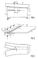
- a plate 1 of brittle material is shown, which is cleft by means of a spot-shaped heat source 3, for example a laser, starting from a crack initiation 5 along the desired cutting line 7.
- the spot-shaped heat source 3 is moved over the plate 1 along the desired cutting line 7.
- the plate 1 is cleft asymmetrically into a wide strip 9 and a narrow strip 11.
- the wide strip 9 is supported during the cleaving operation at two points 13, 15.
- a constant force F is exerted on a corner of the narrow strip 11.
- the value and the direction of the force F are determined empirically or by calculation.
- a spot-shaped heat source 3 use may also be made of a linear heat source.
- a plate 1 of brittle material is cleft asymmetrically in the same manner as in Fig. 1.
- the mechanical load is now provided by constraint, that is to say that the plate 1 is constrained by fixed supports 13, 15 and 17 in the shape it can assume by bending of the strips 9, 11.
- the position of the supports is determined empirically or by calculation.
- a spot-shaped heat source 3 instead of a spot-shaped heat source 3 a linear heat source may be used.
- a plate 1 of brittle material is cleft asymmetrically.
- the mechanical load is provided by a roller 21, which urges by means of a spring or a pneumatic cylinder against the edge of the narrow strip.
- the distance C between the roller 21 and the spot-shaped heat source 3 is kept constant.
- a constant load is obtained with respect to the crack tip 23.
- Even more favourable results are attained if the roller 21 runs over a rigid strip 24, which engages the edge of the plate 1.
- This example is shown in Fig. 4.
- a plate of lime glass is cleft with a beam of a CO2-laser with a spot-diameter of 4 mm and a power of 15 Watt.
- the plate had a width of 37 mm, a length of 87 mm and a thickness of 1 mm.
- the plate was provided with a crack initiation in a side of 37 mm.
- the crack initiation laid 10 mm from a first long side of 87 mm.
- the beam was moved over the plate with a speed of 5 mm/sec.
- the laser beam started at the crack initiation and was moved parallel to the long sides of the plate.
- a metal bar with a width of 15 mm, a length of 100 mm and a thickness of 5 mm laid against the first long side.
- the second long side rested against two pins.
- the broad side without the crack initiation also rested against a pin (not shown).
- C On the distance C, whereby C was 18 mm, the roll was pressed against the metal bar with a force of 40 Newton. The roll was moved simultaneously with the same speed as the laser beam along the plate. The plate was severed along the desired line. The maximum lateral deviation was 0.2 mm. Without the use of the bar, the maximum lateral deviation would have been 0.75 mm.
- the mechanical load is provided on the plate 1 by exerting a frictional force on the surface of the narrow strip 11.
- the narrow strip is clamped in a comparatively rigid clamping device 27.
- the clamping pieces 29 should be sufficiently rough and the clamping force should be sufficiently great.
- This may be obtained, for example, by coating a steel clamp with rubber.
- This material yields a high friction with many materials, inter alia with glass. With a satisfactory dimensioning of the rubber and the clamping force, a mechanical symmetry will occur at the crack tip.
- This method is suitable for use in combination both with a spot-shaped heat source and with a linear heat source.
- the mechanical load is provided on the plate 1 by temporarily securing strengthening material to the narrow strip 11.
- a strip of strengthening material 31 is glued to the narrow strip 11.
- the load around the crack tip 23 is symmetrical.
- the strip of strengthening material 31 is removed from the narrow strip 11.
- the strip 31 can be used again.
- a spot-shaped heat source 3 or a linear heat source may be used.
- the strengthening material may also be secured to the plate by means of two strips glued to the major surfaces of the narrow strip.
- the line glass plate as described above can be severed as follows. A bar of aluminium with a width of 17 mm, a length of 87 mm and a thickness of 1 mm is sealed with cyano-acrylate glue to the first long side of the plate. The plate was severed along the desired line. Nor lateral, nor squareness deviations appeared.
- the material should be a brittle material, such as, for example, glass or silicon.
- a great advantage is that during cleaving no splitters and chips are formed, which could damage the surfaces of the narrow strip. As crack initiation, a scratch or an unevenness provided in the side of the material may be used.
- the major surface of the plate to be cleft may be either flat or curved.
Landscapes
- Engineering & Computer Science (AREA)
- Chemical & Material Sciences (AREA)
- Physics & Mathematics (AREA)
- Mechanical Engineering (AREA)
- Organic Chemistry (AREA)
- Thermal Sciences (AREA)
- Materials Engineering (AREA)
- Optics & Photonics (AREA)
- Toxicology (AREA)
- Life Sciences & Earth Sciences (AREA)
- Forests & Forestry (AREA)
- Health & Medical Sciences (AREA)
- Mining & Mineral Resources (AREA)
- Plasma & Fusion (AREA)
- Re-Forming, After-Treatment, Cutting And Transporting Of Glass Products (AREA)
- Processing Of Stones Or Stones Resemblance Materials (AREA)
Applications Claiming Priority (2)
| Application Number | Priority Date | Filing Date | Title |
|---|---|---|---|
| NL8901144 | 1989-05-08 | ||
| NL8901144 | 1989-05-08 |
Publications (2)
| Publication Number | Publication Date |
|---|---|
| EP0397237A1 true EP0397237A1 (de) | 1990-11-14 |
| EP0397237B1 EP0397237B1 (de) | 1994-05-18 |
Family
ID=19854609
Family Applications (1)
| Application Number | Title | Priority Date | Filing Date |
|---|---|---|---|
| EP90201093A Expired - Lifetime EP0397237B1 (de) | 1989-05-08 | 1990-05-02 | Verfahren zum Spalten einer Platte aus sprödem Werkstoff |
Country Status (4)
| Country | Link |
|---|---|
| US (1) | US5154334A (de) |
| EP (1) | EP0397237B1 (de) |
| JP (1) | JP2835348B2 (de) |
| DE (1) | DE69008927T2 (de) |
Cited By (6)
| Publication number | Priority date | Publication date | Assignee | Title |
|---|---|---|---|---|
| FR2706347A1 (fr) * | 1993-06-09 | 1994-12-23 | Puntous Rene | Procédé et dispositif pour obtenir la rupture fragile d'éléments en acier. |
| US5609284A (en) * | 1992-04-02 | 1997-03-11 | Fonon Technology Limited | Method of splitting non-metallic materials |
| EP0995227A4 (de) * | 1997-05-12 | 2000-07-05 | Silicon Genesis Corp | Kontrolliertes spaltungsverfahren |
| US6420678B1 (en) | 1998-12-01 | 2002-07-16 | Brian L. Hoekstra | Method for separating non-metallic substrates |
| US6489588B1 (en) | 1999-11-24 | 2002-12-03 | Applied Photonics, Inc. | Method and apparatus for separating non-metallic materials |
| RU2305624C1 (ru) * | 2006-02-22 | 2007-09-10 | Государственное образовательное учреждение высшего профессионального образования Волгоградский государственный технический университет (ВолгГТУ) | Способ разделения композиционного материала титан-сталь |
Families Citing this family (15)
| Publication number | Priority date | Publication date | Assignee | Title |
|---|---|---|---|---|
| US5622540A (en) * | 1994-09-19 | 1997-04-22 | Corning Incorporated | Method for breaking a glass sheet |
| JP3923526B2 (ja) * | 1995-08-31 | 2007-06-06 | コーニング インコーポレイテッド | 壊れやすい材料の分断方法および装置 |
| JPH10128567A (ja) * | 1996-10-30 | 1998-05-19 | Nec Kansai Ltd | レーザ割断方法 |
| US6252197B1 (en) | 1998-12-01 | 2001-06-26 | Accudyne Display And Semiconductor Systems, Inc. | Method and apparatus for separating non-metallic substrates utilizing a supplemental mechanical force applicator |
| US6259058B1 (en) | 1998-12-01 | 2001-07-10 | Accudyne Display And Semiconductor Systems, Inc. | Apparatus for separating non-metallic substrates |
| EP1741534A4 (de) * | 2004-04-27 | 2008-09-24 | Mitsuboshi Diamond Ind Co Ltd | Verfahren zur bildung von vertikalbrüchen auf sprödbrettern und vorrichtung zur bildung von vertikalbrüchen |
| DE102004035342B4 (de) * | 2004-07-21 | 2007-12-27 | Schott Ag | Verfahren zum Durchtrennen von Platten aus nichtmetallischen Werkstoffen |
| JP3887394B2 (ja) | 2004-10-08 | 2007-02-28 | 芝浦メカトロニクス株式会社 | 脆性材料の割断加工システム及びその方法 |
| US8051681B2 (en) * | 2007-05-09 | 2011-11-08 | Corning Incorporated | Constant force scoring device and method for using same |
| US7895861B2 (en) * | 2007-05-09 | 2011-03-01 | Corning Incorporated | Conformable nosing device for reducing motion and stress within a glass sheet while manufacturing the glass sheet |
| JP5345334B2 (ja) * | 2008-04-08 | 2013-11-20 | 株式会社レミ | 脆性材料の熱応力割断方法 |
| ES2450520T5 (es) | 2010-03-05 | 2017-08-07 | Sage Electrochromics, Inc. | Laminado de un dispositivo electrocrómico a sustratos de vidrio |
| FR2962682B1 (fr) | 2010-07-16 | 2015-02-27 | Saint Gobain | Vitrage electrochimique a proprietes optiques et/ou energetiques electrocommandables |
| US9272941B2 (en) * | 2012-04-05 | 2016-03-01 | Sage Electrochromics, Inc. | Method of cutting a panel using a starter crack and a glass panel including a starter crack |
| CN106458688A (zh) * | 2014-03-31 | 2017-02-22 | 康宁股份有限公司 | 形成层压玻璃结构的机械加工方法 |
Citations (4)
| Publication number | Priority date | Publication date | Assignee | Title |
|---|---|---|---|---|
| DE1908948A1 (de) * | 1968-02-28 | 1969-10-02 | Ppg Industries Inc | Verfahren und Vorrichtung zum Durchtrennen einer Glasplatte durch Erzeugung thermischer Spannungen |
| US3739963A (en) * | 1971-10-07 | 1973-06-19 | Ppg Industries Inc | Method of and an apparatus for controlling edge flare in thermal cutting |
| FR2319589A1 (fr) * | 1975-08-01 | 1977-02-25 | Saint Gobain | Obtention d'un vitrage par brisure, suivant une ligne de decoupe, des bordures d'une plaque de verre |
| DE2813302B1 (de) * | 1978-03-28 | 1979-01-11 | Fraunhofer Ges Forschung | Verfahren und Vorrichtung zum geradlinigen Schneiden von Flachglas mit Hilfe von thermisch induzierten Spannungen |
Family Cites Families (6)
| Publication number | Priority date | Publication date | Assignee | Title |
|---|---|---|---|---|
| BE559796A (de) * | 1956-10-12 | |||
| US3050906A (en) * | 1960-03-21 | 1962-08-28 | Glaces De Boussois | Method of manufacturing matching sheets of glass |
| DE1244346B (de) | 1964-10-19 | 1967-07-13 | Menzel Gerhard Glasbearbeitung | Verfahren zum Schneiden von Glas |
| US3554722A (en) * | 1968-08-30 | 1971-01-12 | Ford Motor Co | Method of making a glass window structure |
| US4113162A (en) * | 1977-02-09 | 1978-09-12 | Libbey-Owens-Ford Company | Method of and apparatus for thermally severing glass |
| US4670636A (en) * | 1984-09-19 | 1987-06-02 | General Electric Company | Heat assisted parting of amorphous alloys |
-
1990
- 1990-05-02 DE DE69008927T patent/DE69008927T2/de not_active Expired - Fee Related
- 1990-05-02 EP EP90201093A patent/EP0397237B1/de not_active Expired - Lifetime
- 1990-05-08 JP JP2116991A patent/JP2835348B2/ja not_active Expired - Lifetime
-
1991
- 1991-11-22 US US07/799,689 patent/US5154334A/en not_active Expired - Fee Related
Patent Citations (4)
| Publication number | Priority date | Publication date | Assignee | Title |
|---|---|---|---|---|
| DE1908948A1 (de) * | 1968-02-28 | 1969-10-02 | Ppg Industries Inc | Verfahren und Vorrichtung zum Durchtrennen einer Glasplatte durch Erzeugung thermischer Spannungen |
| US3739963A (en) * | 1971-10-07 | 1973-06-19 | Ppg Industries Inc | Method of and an apparatus for controlling edge flare in thermal cutting |
| FR2319589A1 (fr) * | 1975-08-01 | 1977-02-25 | Saint Gobain | Obtention d'un vitrage par brisure, suivant une ligne de decoupe, des bordures d'une plaque de verre |
| DE2813302B1 (de) * | 1978-03-28 | 1979-01-11 | Fraunhofer Ges Forschung | Verfahren und Vorrichtung zum geradlinigen Schneiden von Flachglas mit Hilfe von thermisch induzierten Spannungen |
Cited By (8)
| Publication number | Priority date | Publication date | Assignee | Title |
|---|---|---|---|---|
| US5609284A (en) * | 1992-04-02 | 1997-03-11 | Fonon Technology Limited | Method of splitting non-metallic materials |
| FR2706347A1 (fr) * | 1993-06-09 | 1994-12-23 | Puntous Rene | Procédé et dispositif pour obtenir la rupture fragile d'éléments en acier. |
| EP0995227A4 (de) * | 1997-05-12 | 2000-07-05 | Silicon Genesis Corp | Kontrolliertes spaltungsverfahren |
| US6420678B1 (en) | 1998-12-01 | 2002-07-16 | Brian L. Hoekstra | Method for separating non-metallic substrates |
| US6489588B1 (en) | 1999-11-24 | 2002-12-03 | Applied Photonics, Inc. | Method and apparatus for separating non-metallic materials |
| US6660963B2 (en) | 1999-11-24 | 2003-12-09 | Applied Photonics, Inc. | Method and apparatus for separating non-metallic materials |
| EP1232038B1 (de) * | 1999-11-24 | 2008-04-23 | Applied Photonics, Inc. | Verfahren und vorrichtung zum trennen nichtmetallischer materialien |
| RU2305624C1 (ru) * | 2006-02-22 | 2007-09-10 | Государственное образовательное учреждение высшего профессионального образования Волгоградский государственный технический университет (ВолгГТУ) | Способ разделения композиционного материала титан-сталь |
Also Published As
| Publication number | Publication date |
|---|---|
| JP2835348B2 (ja) | 1998-12-14 |
| JPH02296745A (ja) | 1990-12-07 |
| EP0397237B1 (de) | 1994-05-18 |
| US5154334A (en) | 1992-10-13 |
| DE69008927D1 (de) | 1994-06-23 |
| DE69008927T2 (de) | 1994-12-01 |
Similar Documents
| Publication | Publication Date | Title |
|---|---|---|
| EP0397237B1 (de) | Verfahren zum Spalten einer Platte aus sprödem Werkstoff | |
| US4234176A (en) | Quick release clamp | |
| EP0938946A1 (de) | Unter Verwendung einer eine thermische Spannung erzeugenden punktlichen Wärmequelle, Verfahren zum Spalten von Sprödenwerkstoff | |
| JPH10128567A (ja) | レーザ割断方法 | |
| JPH07214355A (ja) | シート状金属片を正確につき合わせる装置 | |
| JPH05277984A (ja) | 積重金属板の断裁刃 | |
| JPH06222249A (ja) | 光ファイバのアライメント装置及び光電子部品 | |
| US4607775A (en) | Device for cutting glass fibers | |
| EP0737119B1 (de) | Räumliches einstellgerät einer einrichtung, zum blechschweissen | |
| GB2029402A (en) | Cutting glass | |
| US5213244A (en) | Oblique fracturing of optical fibers by angled scoring | |
| US4289261A (en) | Method of thermally inducing bending moment forces to sever a glass sheet along a score | |
| JPS6037296A (ja) | 溶接用エンドタブ | |
| CN113490648A (zh) | 通过抵靠弯曲模板进行压制来弯曲玻璃片材的方法和装置 | |
| US3739963A (en) | Method of and an apparatus for controlling edge flare in thermal cutting | |
| UA11088A (uk) | Машиhа для устаhовки та зhяття hакладок | |
| JP2634556B2 (ja) | プラスチック段ボールの曲げ加工装置 | |
| JP2002110589A (ja) | 割断装置及びその方法 | |
| CN221910503U (zh) | 薄板焊接反变形工装 | |
| JPH0254206A (ja) | 光フアイバの切断方法 | |
| JP2006137168A (ja) | 脆性材料の割断方法及び装置 | |
| JP2794935B2 (ja) | 加熱板の接合方法およびその装置 | |
| JPH07189417A (ja) | ろう付けアルミニウムハニカムパネルの製造方法 | |
| EP0658132B1 (de) | Ausrichten von zu schweissenden blechkanten | |
| JPH11104868A (ja) | 脆性材料の割断方法および割断装置 |
Legal Events
| Date | Code | Title | Description |
|---|---|---|---|
| PUAI | Public reference made under article 153(3) epc to a published international application that has entered the european phase |
Free format text: ORIGINAL CODE: 0009012 |
|
| AK | Designated contracting states |
Kind code of ref document: A1 Designated state(s): DE FR GB IT |
|
| 17P | Request for examination filed |
Effective date: 19910513 |
|
| 17Q | First examination report despatched |
Effective date: 19920811 |
|
| GRAA | (expected) grant |
Free format text: ORIGINAL CODE: 0009210 |
|
| AK | Designated contracting states |
Kind code of ref document: B1 Designated state(s): DE FR GB IT |
|
| PG25 | Lapsed in a contracting state [announced via postgrant information from national office to epo] |
Ref country code: IT Free format text: LAPSE BECAUSE OF FAILURE TO SUBMIT A TRANSLATION OF THE DESCRIPTION OR TO PAY THE FEE WITHIN THE PRE;WARNING: LAPSES OF ITALIAN PATENTS WITH EFFECTIVE DATE BEFORE 2007 MAY HAVE OCCURRED AT ANY TIME BEFORE 2007. THE CORRECT EFFECTIVE DATE MAY BE DIFFERENT FROM THE ONE RECORDED.SCRIBED TIME-LIMIT Effective date: 19940518 |
|
| REF | Corresponds to: |
Ref document number: 69008927 Country of ref document: DE Date of ref document: 19940623 |
|
| ET | Fr: translation filed | ||
| PLBE | No opposition filed within time limit |
Free format text: ORIGINAL CODE: 0009261 |
|
| 26N | No opposition filed | ||
| REG | Reference to a national code |
Ref country code: FR Ref legal event code: CD |
|
| PGFP | Annual fee paid to national office [announced via postgrant information from national office to epo] |
Ref country code: GB Payment date: 19980501 Year of fee payment: 9 |
|
| PGFP | Annual fee paid to national office [announced via postgrant information from national office to epo] |
Ref country code: FR Payment date: 19980519 Year of fee payment: 9 |
|
| PGFP | Annual fee paid to national office [announced via postgrant information from national office to epo] |
Ref country code: DE Payment date: 19980724 Year of fee payment: 9 |
|
| REG | Reference to a national code |
Ref country code: FR Ref legal event code: CD |
|
| PG25 | Lapsed in a contracting state [announced via postgrant information from national office to epo] |
Ref country code: GB Free format text: LAPSE BECAUSE OF NON-PAYMENT OF DUE FEES Effective date: 19990502 |
|
| GBPC | Gb: european patent ceased through non-payment of renewal fee |
Effective date: 19990502 |
|
| PG25 | Lapsed in a contracting state [announced via postgrant information from national office to epo] |
Ref country code: FR Free format text: LAPSE BECAUSE OF NON-PAYMENT OF DUE FEES Effective date: 20000131 |
|
| PG25 | Lapsed in a contracting state [announced via postgrant information from national office to epo] |
Ref country code: DE Free format text: LAPSE BECAUSE OF NON-PAYMENT OF DUE FEES Effective date: 20000301 |
|
| REG | Reference to a national code |
Ref country code: FR Ref legal event code: ST |