EP0394555B1 - Lenkrolle für fahrbare Geräte - Google Patents
Lenkrolle für fahrbare Geräte Download PDFInfo
- Publication number
- EP0394555B1 EP0394555B1 EP19890123093 EP89123093A EP0394555B1 EP 0394555 B1 EP0394555 B1 EP 0394555B1 EP 19890123093 EP19890123093 EP 19890123093 EP 89123093 A EP89123093 A EP 89123093A EP 0394555 B1 EP0394555 B1 EP 0394555B1
- Authority
- EP
- European Patent Office
- Prior art keywords
- rich
- guide housing
- securing plate
- castor
- spring
- Prior art date
- Legal status (The legal status is an assumption and is not a legal conclusion. Google has not performed a legal analysis and makes no representation as to the accuracy of the status listed.)
- Expired - Lifetime
Links
- 235000004443 Ricinus communis Nutrition 0.000 title claims description 8
- 230000005540 biological transmission Effects 0.000 claims description 18
- 210000002105 tongue Anatomy 0.000 description 5
- 230000006835 compression Effects 0.000 description 3
- 238000007906 compression Methods 0.000 description 3
- 230000000903 blocking effect Effects 0.000 description 2
- 230000015572 biosynthetic process Effects 0.000 description 1
- 238000006073 displacement reaction Methods 0.000 description 1
- 238000005755 formation reaction Methods 0.000 description 1
- 238000004519 manufacturing process Methods 0.000 description 1
- 230000013011 mating Effects 0.000 description 1
- 238000000034 method Methods 0.000 description 1
- 238000003466 welding Methods 0.000 description 1
Images
Classifications
-
- B—PERFORMING OPERATIONS; TRANSPORTING
- B60—VEHICLES IN GENERAL
- B60B—VEHICLE WHEELS; CASTORS; AXLES FOR WHEELS OR CASTORS; INCREASING WHEEL ADHESION
- B60B33/00—Castors in general; Anti-clogging castors
- B60B33/02—Castors in general; Anti-clogging castors with disengageable swivel action, i.e. comprising a swivel locking mechanism
- B60B33/021—Castors in general; Anti-clogging castors with disengageable swivel action, i.e. comprising a swivel locking mechanism combined with braking of castor wheel
Definitions
- the invention relates to a swivel castor for mobile devices, in particular refuse containers, with a locking device which has an actuating cam mounted in a guide housing connected to a mounting plate, which acts on an adjusting bolt which is arranged in the guide housing in a non-rotatable but axially displaceable manner and which penetrates a bearing head centrally and which protruding through the wheel fork back into the wheel fork cavity is loaded by a self-resetting brake lug in the release direction, and which is connected in a rotationally fixed manner to a locking star which rests on its shoulder and is supported by a spring in the locking direction and can be connected to the wheel fork in a form-fitting manner, one end acting on the locking star Spring is supported on the other side of the guide housing.
- the locking star is non-rotatably connected to the wheel fork when it is locked and is in turn also held non-rotatably on the adjusting bolt, which in turn engages non-rotatably in the guide housing.
- This guide housing is encompassed by a tubular casing which is firmly connected to the fastening plate and which has flanged tongues in receptacles of the Guide housing engages to secure it against rotation. The torque transmission now takes the path from the locking star via the adjusting bolt, the guide housing and the pipe jacket to the mounting plate.
- the torque resulting from the locked pivoting movement can be relatively high in special cases, for example when the mobile device is found on an inclined surface, so that the components can easily be damaged due to the long transmission path of the torque, for weight saving reasons for example, could be made of plastic, as is desirable for the guide housing.
- the object of the present invention is to improve a steering roller of the type mentioned in such a way that a torque introduced by the locking star in the adjusting bolt can be introduced in a short way and directly into the fastening plate.
- a transmission disc which is arranged between the guide housing and the spring and which encompasses the adjusting bolt in a form-fitting and non-rotatable manner is also in a form-fitting and non-rotatable engagement with the fastening plate.
- the transmission disk which has a square shaft of the adjusting bolt, has at least one recess on its circumference, into which a Projection of the mounting plate engages.
- the transmission disk has a plurality of recesses distributed around its circumference, into which a corresponding number of projections of the fastening plate engage.
- a simple design of the projections in terms of material expenditure and production is achieved by the projections being formed by formations on the central connecting collar of the fastening plate.
- the impeller 10 is mounted between the legs of a wheel fork 11 on an axis crossing the fork legs, the fork legs being integrally connected to one another by the fork back 12.
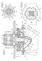
- the fork back 12 which is pressed out like a pot in its center, forms a bearing head 15, which is on its pot bottom as a raceway for two Spheres are prepared, and the one between a, formed by a connecting collar 40, central bore 16 having mounting plate 17 and a centrally connected bearing ring 18. Both the mounting plate 17 and the bearing ring 18 each have a mating track for the spherical rings supported on the pot base 14.
- a tubular casing 19 is fastened centrally to the bore 16 on the mounting plate 17 of the bearing head 15, for example by welding, two half-shells 21 and 22 forming a guide housing 20 being positively fixed in the tubular casing 19 by tongues 13 flanged on top in recesses in the half-shells.
- the guide housing 20 has on the underside a receiving space for the square shank 24 of an adjusting bolt 23, which rests on the upper side with a spherical cap 25 on the control cam (not shown) of a cam 26.
- this control curve comprises a latching recess and a locking curve section which rises with respect to the locking movement.
- the cam 26 is supported with its more than semicircular outer circumference on a semicircular guideway in the receiving space of the half-shells 21 and 22 and has stop lugs which can alternately attach to the horizontal walls of the half-shells 21 and 22 depending on the position to limit the stop.
- In the center of the cam there is an out-of-round driver bore 27 into which the out-of-round section of an actuating shaft (not shown) can engage.
- the guide sleeve 32 is designed as a one-piece molded part of a holding plate 33 which is firmly connected to the wheel fork back and bridges the wheel fork cavity.
- the guide sleeve 32 forms the extension of a recess 35 of the holding plate 33, which receives a disc-shaped locking star 34 in a form-fitting manner.
- This holding plate 33 has sections on both sides of its guide sleeve, into which pronounced holding tongues 36 of the fork back 12 engage, which on the underside of the holding plate 33 also lead to the latter Fixing on the fork back 12 are bent.
- the cap nut 30 is acted upon on the underside by a brake lug 37 which is fixed on the fork back 12 and resiliently resilient in the sense of release.
- This locking star 34 which encompasses the square shank 24 in a form-fitting manner, can be taken along in the release direction by corners 39 which protrude on the underside of the chamfers of the square shank 24. In the locking position shown in FIG. 1, the locking star 34 engages in the recess 35 of the holding plate 33 which has a corresponding internal toothing.
- the other end of the compression spring 38 lies under the aforementioned transmission disk 29, which on the one hand engages around the square shaft 24 of the adjusting bolt 23 in a form-fitting manner and, on the other hand, on its outer circumference has at least one, in the exemplary embodiment shown and particularly evident from FIG. 2, four recesses 41.
- These recesses 41 of the transmission disk 29 encompass projections 42, which are formed as protrusions from the connecting collar 40 in the lower edge region in one stamping process. Characterized the adjusting bolt 23 is fixed by the transmission disc 29 directly on the mounting plate 17 torque-transmitting.
Landscapes
- Engineering & Computer Science (AREA)
- Mechanical Engineering (AREA)
- Braking Arrangements (AREA)
- Handcart (AREA)
Applications Claiming Priority (2)
| Application Number | Priority Date | Filing Date | Title |
|---|---|---|---|
| DE3913690 | 1989-04-26 | ||
| DE19893913690 DE3913690A1 (de) | 1989-04-26 | 1989-04-26 | Lenkrolle fuer fahrbare geraete |
Publications (2)
| Publication Number | Publication Date |
|---|---|
| EP0394555A1 EP0394555A1 (de) | 1990-10-31 |
| EP0394555B1 true EP0394555B1 (de) | 1992-04-15 |
Family
ID=6379466
Family Applications (1)
| Application Number | Title | Priority Date | Filing Date |
|---|---|---|---|
| EP19890123093 Expired - Lifetime EP0394555B1 (de) | 1989-04-26 | 1989-12-14 | Lenkrolle für fahrbare Geräte |
Country Status (3)
| Country | Link |
|---|---|
| EP (1) | EP0394555B1 (enExample) |
| DE (1) | DE3913690A1 (enExample) |
| ES (1) | ES2030965T3 (enExample) |
Families Citing this family (7)
| Publication number | Priority date | Publication date | Assignee | Title |
|---|---|---|---|---|
| DE9212138U1 (de) * | 1992-09-09 | 1992-11-12 | Albert Schulte Söhne GmbH & Co, 5632 Wermelskirchen | Feststellbare Lenkrolle für verfahrbare Geräte |
| ES2115808T3 (es) * | 1993-06-29 | 1998-07-01 | Tellure Rota Spa | Rueda orientable bloqueable para soportar un cuerpo desplazable, en particular un contenedor de basura. |
| DE29616076U1 (de) * | 1996-09-16 | 1996-11-07 | Rhombus Rollen GmbH & Co., 42929 Wermelskirchen | Lenkrolle für verfahrbare Geräte |
| ATE296729T1 (de) * | 2000-11-21 | 2005-06-15 | Arrow Technology Systems Ltd | Radmechanismus für wagen |
| NO316760B1 (no) * | 2002-07-30 | 2004-04-26 | Rolf Libakken | Rulle-/fotanordning |
| DE10256626A1 (de) * | 2002-12-03 | 2004-06-24 | Steinco Paul Vom Stein Gmbh | Lenkrolle |
| DE102019123213B3 (de) * | 2019-08-29 | 2020-12-03 | BS Rollen GmbH | Rollenbefestigung |
Family Cites Families (5)
| Publication number | Priority date | Publication date | Assignee | Title |
|---|---|---|---|---|
| CH475107A (de) * | 1967-07-31 | 1969-07-15 | Happe & Co | Feststellvorrichtung für an fahrbaren Gegenständen angebrachte Lenkrollen |
| DE2136353A1 (de) * | 1971-07-21 | 1973-02-15 | Schulte & Co Kugelfab | Lenkrolle mit feststellvorrichtung |
| DE2344208C3 (de) * | 1973-09-01 | 1978-05-24 | Acousa Saxon S.A., Saxon (Schweiz) | Zentral feststellbare Lenkrolle, insbesondere für verfahrbare Krankenbetten |
| DE3031345A1 (de) * | 1980-08-20 | 1982-04-01 | Albert Schulte Söhne KG, 5632 Wermelskirchen | Feststellbare lenkrolle fuer verfahrbare geraete |
| DE3531824A1 (de) * | 1985-09-06 | 1987-03-19 | Tente Rollen Gmbh & Co | Lenkrolle |
-
1989
- 1989-04-26 DE DE19893913690 patent/DE3913690A1/de active Granted
- 1989-12-14 EP EP19890123093 patent/EP0394555B1/de not_active Expired - Lifetime
- 1989-12-14 ES ES89123093T patent/ES2030965T3/es not_active Expired - Lifetime
Also Published As
| Publication number | Publication date |
|---|---|
| ES2030965T3 (es) | 1992-11-16 |
| EP0394555A1 (de) | 1990-10-31 |
| DE3913690C2 (enExample) | 1991-02-28 |
| DE3913690A1 (de) | 1990-10-31 |
Similar Documents
| Publication | Publication Date | Title |
|---|---|---|
| DE3528591C2 (enExample) | ||
| DE4301403A1 (de) | Zentralschloß für Mehrpunktsicherheitsgurte | |
| DE10106915A1 (de) | Federungsanordnung | |
| DE2622908A1 (de) | Fahrzeugradkappe | |
| EP2802481B1 (de) | Beschlag für einen fahrzeugsitz, sowie fahrzeugsitz | |
| DE2459030A1 (de) | Sicherheitsverschluss fuer behaelter | |
| DE2727034A1 (de) | Verriegelungsmechanismus und damit ausgeruestete kraftfahrzeuge mit kippbarem fahrerhaus | |
| EP0115774B1 (de) | Federnspanner | |
| WO2015154763A1 (de) | Vorrichtung zur höhenverstellung eines fahrzeugaufbaus | |
| EP0529251B1 (de) | Schalthebellagerung für Getriebe von Kraftfahrzeugen | |
| EP1284447B1 (de) | Schwenkbeschlag | |
| EP0394555B1 (de) | Lenkrolle für fahrbare Geräte | |
| DE102015206149B4 (de) | Vorrichtung zur Höhenverstellung eines Fahrzeugaufbaus | |
| DE19945255A1 (de) | Radlagerung, insbesondere für nichtangetriebene Fahrzeugachsen | |
| EP0388652B1 (de) | Feststellvorrichtung für Lenkrollen | |
| DE19921810B4 (de) | Rastbeschlag für einen Fahrzeugsitz | |
| EP0583580A2 (de) | Gabelgelenk | |
| DE3039968A1 (de) | Schaltwerk | |
| DE3625676A1 (de) | Axial-ueberlastelement | |
| DE2747934A1 (de) | Elektromagnetisch betaetigte zahnkupplung | |
| DE2747152C3 (de) | Vielfachdrehumschalter | |
| DE29706629U1 (de) | Kontakteinheit mit Stator und Rotor, insbesondere für das Lenkrad eines Kraftfahrzeuges | |
| DE2647027B2 (de) | Handhabenlagerung aus Kunststoff | |
| EP0318459A2 (de) | Spindelantrieb | |
| DE69303636T2 (de) | Wagenheber |
Legal Events
| Date | Code | Title | Description |
|---|---|---|---|
| PUAI | Public reference made under article 153(3) epc to a published international application that has entered the european phase |
Free format text: ORIGINAL CODE: 0009012 |
|
| AK | Designated contracting states |
Kind code of ref document: A1 Designated state(s): ES FR GB IT NL |
|
| 17P | Request for examination filed |
Effective date: 19901113 |
|
| 17Q | First examination report despatched |
Effective date: 19910414 |
|
| ITF | It: translation for a ep patent filed | ||
| GRAA | (expected) grant |
Free format text: ORIGINAL CODE: 0009210 |
|
| AK | Designated contracting states |
Kind code of ref document: B1 Designated state(s): ES FR GB IT NL |
|
| ET | Fr: translation filed | ||
| GBT | Gb: translation of ep patent filed (gb section 77(6)(a)/1977) | ||
| REG | Reference to a national code |
Ref country code: ES Ref legal event code: FG2A Ref document number: 2030965 Country of ref document: ES Kind code of ref document: T3 |
|
| PLBE | No opposition filed within time limit |
Free format text: ORIGINAL CODE: 0009261 |
|
| STAA | Information on the status of an ep patent application or granted ep patent |
Free format text: STATUS: NO OPPOSITION FILED WITHIN TIME LIMIT |
|
| 26N | No opposition filed | ||
| PGFP | Annual fee paid to national office [announced via postgrant information from national office to epo] |
Ref country code: GB Payment date: 19951213 Year of fee payment: 7 |
|
| PGFP | Annual fee paid to national office [announced via postgrant information from national office to epo] |
Ref country code: FR Payment date: 19951215 Year of fee payment: 7 Ref country code: ES Payment date: 19951215 Year of fee payment: 7 |
|
| PGFP | Annual fee paid to national office [announced via postgrant information from national office to epo] |
Ref country code: NL Payment date: 19951230 Year of fee payment: 7 |
|
| PG25 | Lapsed in a contracting state [announced via postgrant information from national office to epo] |
Ref country code: GB Effective date: 19961214 |
|
| PG25 | Lapsed in a contracting state [announced via postgrant information from national office to epo] |
Ref country code: NL Effective date: 19970701 |
|
| GBPC | Gb: european patent ceased through non-payment of renewal fee |
Effective date: 19961214 |
|
| PG25 | Lapsed in a contracting state [announced via postgrant information from national office to epo] |
Ref country code: FR Effective date: 19970829 |
|
| NLV4 | Nl: lapsed or anulled due to non-payment of the annual fee |
Effective date: 19970701 |
|
| REG | Reference to a national code |
Ref country code: FR Ref legal event code: ST |
|
| PG25 | Lapsed in a contracting state [announced via postgrant information from national office to epo] |
Ref country code: ES Free format text: LAPSE BECAUSE OF NON-PAYMENT OF DUE FEES Effective date: 19971215 |
|
| REG | Reference to a national code |
Ref country code: ES Ref legal event code: FD2A Effective date: 19980113 |
|
| PG25 | Lapsed in a contracting state [announced via postgrant information from national office to epo] |
Ref country code: IT Free format text: LAPSE BECAUSE OF NON-PAYMENT OF DUE FEES;WARNING: LAPSES OF ITALIAN PATENTS WITH EFFECTIVE DATE BEFORE 2007 MAY HAVE OCCURRED AT ANY TIME BEFORE 2007. THE CORRECT EFFECTIVE DATE MAY BE DIFFERENT FROM THE ONE RECORDED. Effective date: 20051214 |