EP0389783B1 - Fastener assembly with sealing grommet - Google Patents
Fastener assembly with sealing grommet Download PDFInfo
- Publication number
- EP0389783B1 EP0389783B1 EP90103206A EP90103206A EP0389783B1 EP 0389783 B1 EP0389783 B1 EP 0389783B1 EP 90103206 A EP90103206 A EP 90103206A EP 90103206 A EP90103206 A EP 90103206A EP 0389783 B1 EP0389783 B1 EP 0389783B1
- Authority
- EP
- European Patent Office
- Prior art keywords
- fastener
- washer
- work piece
- grommet
- sleeve
- Prior art date
- Legal status (The legal status is an assumption and is not a legal conclusion. Google has not performed a legal analysis and makes no representation as to the accuracy of the status listed.)
- Expired - Lifetime
Links
- 238000007789 sealing Methods 0.000 title claims description 28
- 239000012530 fluid Substances 0.000 claims abstract description 14
- 230000006835 compression Effects 0.000 claims description 3
- 238000007906 compression Methods 0.000 claims description 3
- 239000003566 sealing material Substances 0.000 claims description 3
- 239000000463 material Substances 0.000 description 6
- 239000011324 bead Substances 0.000 description 5
- 239000011248 coating agent Substances 0.000 description 4
- 238000000576 coating method Methods 0.000 description 4
- 230000000717 retained effect Effects 0.000 description 4
- 230000000712 assembly Effects 0.000 description 2
- 238000000429 assembly Methods 0.000 description 2
- 230000003028 elevating effect Effects 0.000 description 2
- 229910000831 Steel Inorganic materials 0.000 description 1
- 230000000295 complement effect Effects 0.000 description 1
- 238000009434 installation Methods 0.000 description 1
- 230000003993 interaction Effects 0.000 description 1
- 230000014759 maintenance of location Effects 0.000 description 1
- 239000003921 oil Substances 0.000 description 1
- 239000003209 petroleum derivative Substances 0.000 description 1
- 239000010959 steel Substances 0.000 description 1
- 229920002994 synthetic fiber Polymers 0.000 description 1
Images
Classifications
-
- F—MECHANICAL ENGINEERING; LIGHTING; HEATING; WEAPONS; BLASTING
- F16—ENGINEERING ELEMENTS AND UNITS; GENERAL MEASURES FOR PRODUCING AND MAINTAINING EFFECTIVE FUNCTIONING OF MACHINES OR INSTALLATIONS; THERMAL INSULATION IN GENERAL
- F16B—DEVICES FOR FASTENING OR SECURING CONSTRUCTIONAL ELEMENTS OR MACHINE PARTS TOGETHER, e.g. NAILS, BOLTS, CIRCLIPS, CLAMPS, CLIPS OR WEDGES; JOINTS OR JOINTING
- F16B41/00—Measures against loss of bolts, nuts, or pins; Measures against unauthorised operation of bolts, nuts or pins
- F16B41/002—Measures against loss of bolts, nuts or pins
-
- F—MECHANICAL ENGINEERING; LIGHTING; HEATING; WEAPONS; BLASTING
- F02—COMBUSTION ENGINES; HOT-GAS OR COMBUSTION-PRODUCT ENGINE PLANTS
- F02B—INTERNAL-COMBUSTION PISTON ENGINES; COMBUSTION ENGINES IN GENERAL
- F02B77/00—Component parts, details or accessories, not otherwise provided for
-
- F—MECHANICAL ENGINEERING; LIGHTING; HEATING; WEAPONS; BLASTING
- F16—ENGINEERING ELEMENTS AND UNITS; GENERAL MEASURES FOR PRODUCING AND MAINTAINING EFFECTIVE FUNCTIONING OF MACHINES OR INSTALLATIONS; THERMAL INSULATION IN GENERAL
- F16B—DEVICES FOR FASTENING OR SECURING CONSTRUCTIONAL ELEMENTS OR MACHINE PARTS TOGETHER, e.g. NAILS, BOLTS, CIRCLIPS, CLAMPS, CLIPS OR WEDGES; JOINTS OR JOINTING
- F16B33/00—Features common to bolt and nut
- F16B33/06—Surface treatment of parts furnished with screw-thread, e.g. for preventing seizure or fretting
-
- F—MECHANICAL ENGINEERING; LIGHTING; HEATING; WEAPONS; BLASTING
- F16—ENGINEERING ELEMENTS AND UNITS; GENERAL MEASURES FOR PRODUCING AND MAINTAINING EFFECTIVE FUNCTIONING OF MACHINES OR INSTALLATIONS; THERMAL INSULATION IN GENERAL
- F16B—DEVICES FOR FASTENING OR SECURING CONSTRUCTIONAL ELEMENTS OR MACHINE PARTS TOGETHER, e.g. NAILS, BOLTS, CIRCLIPS, CLAMPS, CLIPS OR WEDGES; JOINTS OR JOINTING
- F16B43/00—Washers or equivalent devices; Other devices for supporting bolt-heads or nuts
- F16B43/001—Washers or equivalent devices; Other devices for supporting bolt-heads or nuts for sealing or insulation
Definitions
- This invention relates to a fastener assembly according to the preamble portion of patent claim 1.
- fastener assemblies are required to seal the apertures in which they are inserted against fluid flow and to securely retain the assembly in an elevated position to avoid interference with surfaces on which the preassembled work piece may be placed during assembly or while in storage.
- a general object of the invention is to provide an axially movable threaded fastener assembly which completely seals the aperture through which it is installed against fluid flow from the inside of the work pieces which it fastens, and which retains a fastener in a freely axially movable configuration which permits the fastener to be moved into an elevated position with respect to a work piece with which it is preassembled to prevent the fastener from projecting through the bottom surface of the work piece, thus preventing interference with other surfaces.
- the present invention comprises an axially movable threaded fastener assembly with a fastener, washer, and a grommet of rubber or other resilient sealing material which completely seals the apertures through which it is inserted, and prior to final installation, the assembly retains the fastener in an elevated position to prevent the fastener from projecting through the bottom surface of a work piece to prevent interference with outer surfaces.
- the amount of compression created by the fastener on the resilient grommet and the resilient gasket is limited.
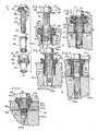
- Fig. 1 shows an exploded view of a fastener assembly 10 illustrating the relationship between a fastener 12, a washer 14 and a resilient grommet 16.
- the fastener 12 which is formed of steel or other suitable rigid material, is comprised of a head portion 18, including a tool engaging section 20 and a clamping surface 22, attached to an axially projecting shank portion 24.
- the shank portion 24 is formed with an upper shank section 26, two protuberant wings 28, a lower threaded shank section 30, and a reduced diameter entering end 32.
- the wings or protuberances 28 are integrally formed on the shank 24 between the upper shank portion 26 and the threaded lower shank portion 30 at approximately 180° to each other.
- the washer 14 is comprised of a flange portion 34 and a sleeve portion 36 extending axially therefrom and having an annular crimp or internal bead 38 formed therebetween.
- the washer 14 includes a central bore 25 which slidably receives the shank portion 24 which projects through the washer bore 25 and is held in place by the crimp or bead material 38 which provides inwardly projecting abutment means of reduced internal diameter which is smaller than the dimension from wing tip 28 to wing tip 28.
- a flare 40 is formed at the distal end of the washer sleeve 36 for the purpose described below.
- the washer 14 telescopically extends through a central bore 41 in the grommet 16.
- the grommet 16 has a body portion 42 around which is formed an annular radially projecting gripping and sealing flange or bead 44.
- An annular sealing ring 46 projects axially from an end face of the body 42 and a sleeve 48 of substantial length also extends axially from an inner annular margin of the body 42.
- the fastener assembly 10 is adapted to be preassembled with a first work piece 50 for subsequently securing the first work piece 50 to a second work piece 52.
- the work piece 50 is formed with a bore or aperture 54 having an enlarged outer end or counterbore 58 for receiving the fastener assembly.
- the work piece 52 is formed with an internally threaded aperture 56 positioned for alignment with the aperture 54.
- the annular bore gripping flange 44 helps to compressibly hold the grommet 16 and fastener 12 retained therein when inserted into the aperture 54 in a first work piece.
- the grommet 16 is integrally formed of a resilient rubber or other suitable synthetic material which is resistant to the fluids which may be encountered in sealing an aperture, such as oils and other petroleum products in an automotive application.
- Fig. 2 shows the components of the preassembled fastener assembly 10 in a partially assembled condition.
- the crimp or bead 38 has a smaller diameter than the wings 28 on the shank 24, thereby allowing relative axial movement between the fastener 12 and washer 14, which movement is limited by the spacing of the wings 28 from the clamping surface 22.
- the manner in which the flare 40 distorts the sleeve 48 of the rubber grommet 16. Since the outside diameter of the flare 40 is greater than the inside diameter of the rubber grommet sleeve 48, the sleeve 48 must be stretched over the flare portion 40 which aids in retaining the grommet 16 on the washer 14. As shown in Fig.
- the fastener 12 when the fastener assembly 10 is preassembled with the work piece 50, the fastener 12 can be displaced upwardly so that its lower end does not project below the bottom surface of the work piece. This facilitates subsequent positioning and alignment of the work piece 50 with the second work piece 52.
- FIG. 3 provides the best illustration of the use of the preferred embodiment of the fastener assembly 10.
- the first work piece 50 is positioned over the second work piece 52 such that the apertures 54, 56 of the two work pieces are substantially aligned.
- the fastener 12 of the assembly 10 which has been preassembled with the work piece 50 is pushed through the aperture 54 of the first work piece 50 to bring the threaded portion of the shank 30 in aligned interengagement with the complementarily threaded aperture 56 in the second work piece 52.
- the rubber grommet 16 becomes seated in the counterbore 58.
- the washer 14 is dimensioned and formed to provide space between the washer 14, shank 24 and bore 25 thus allowing free telescoping movement between the pieces, two potential fluid flow paths are formed through the aperture 54 of the first work piece 50.
- the first path is formed by the gap 59 between the inside surface of the aperture 54 and the outside surface of the washer sleeve 36. This path is at least partially sealed by the rubber grommet sleeve 48 which compressibly fills the gap between the two surfaces.
- the rubber grommet 14 also seals this gap against fluid flow from inside of the assembled work pieces 50, 52, by the sealing engagement of the annular sealing ring 46 with the bottom of the counterbore 58 and sealing engagement of the flange 44 with the sidewall of the counterbore 58.
- the second fluid flow path is formed by a gap 60 between the outside surface of the fastener shank 24 and the inside surface of the washer sleeve 36.
- This gap 60 is sealed by compressing the underside of the clamping surface 22 sealingly against an axially extending annular rim 47 of the grommet body 42 which projects around the flange 34 of the washer.
- the washer flange 34 seats in a rim counterbore 61, thereby sealing the washer flange 34 against the base of the rim counterbore 61 and countersinking the flange 34 to prevent interference with the seal between the clamping surface 22 and the annular sealing rim 47.
- the above described sealing structure has the advantage of effectively sealing the aperture 54 while retaining the telescopically movable characteristics of the fastener 12 by positioning the sealing material on the outside of the washer 14. Additionally, the grommet 16 configuration of the present invention and the annular bore gripping flange 44 help to center the fastener assembly 10 when inserted in the aperture 54. The annular bore gripping flange 44 also assists in retaining the fastener assembly 10 within the aperture of the first work piece 50 prior to final assembly with the second work piece 52 by compressibly gripping the inside wall of the counterbore 58.
- a simplified version of rubber grommet 16a which has a fastener elevating annular ring 62 formed around the inside wall of the rubber grommet sleeve 48a.
- the annular ring 62 is dimensioned to provide a minor obstruction to the passage of the assembled washer 14a and fastener 12a through the grommet sleeve 48a. The obstruction created by the ring 62 elevates the fastener 12a and suspends the washer 14a in the aperture 54a.
- the washer flange 34a engages the clamping surface 22a, thus limiting the axial travel of the fastener 12a in the washer 14a and grommet 16a.
- the obstruction is easily overcome by the pressure and/or the weight of a tool applied to the tool engaging member 20a to drive the threaded portion of the shank 30a into the complementary threaded aperture 56a of the second work piece 52a.
- Retention of the washer 14a and the fastener 12a in this elevated configuration allows the fastener assembly 10a to be preassembled in the first work piece 50a so that when the work piece 50a is placed on another surface or on top of the second work piece 52a, prior to aligning the aperture 54a in the first work piece 50a with the aperture 56a in the second work piece 52a, the fastener 12a does not project through the bottom of the first workpiece and therefore does not interfere with the other surface. Further, the retaining characteristics of the fastener assembly 10a tolerate a degree of tip without unseating the fastener assembly 10a from the aperture 54a in the first work piece 50a.
- Fig. 5 illustrates the fastener assembly 10a as shown in Fig. 4 installed in the first and second work pieces 50a, 52a.
- the fastener elevating annular ring 62 is compressed between the inside surface of the aperture 54a and the outside surface of the washer sleeve 36a to form a sealing couple with the flare 40a of the washer sleeve 48a.
- FIG. 6 Another alternative embodiment of the present invention is illustrated in Fig. 6 wherein elements corresponding to those described above are designated by the same reference numerals with the suffix b added.
- the embodiment shown in Fig. 6 provides a simplified grommet which is formed without the above-mentioned counterbore 61.
- the exposed rim 47 seals the path between the inside surface of the washer 14 and the outside surface of the fastener 12 (see Figs. 2-5).
- a resilient coating material 68 is applied to the threaded portion 30b of the shank 24b. This coating material seals both the inside surface of the washer and the threads in the secondary work piece aperture 56b.
- the fastener assembly 10 is inserted into an aperture 54 on the first work piece 50. Once inserted, the fastener assembly 10 is retained in the aperture 54 by the frictional interaction between the outside surface of the grommet 16 and the inside surface of the aperture 54. The fastener 12 may be held and retained in an elevated position within the grommet 16 while positioning the work piece 50 over the work piece 52. The fastener 12 is extended to interengage the threaded aperture 56 of the second work piece 52.
- the fastener assembly 10 prevents fluid flow from the inside of the assembled work pieces.
- the fluid flow path formed by the gap 59 between the inside surface of the aperture 54 and the outside surface of the washer 14 is sealed by the sleeve 36 lining the aperture 54 in the first work piece 50 and the body portion 42 being radially compressed into the counterbore 58 of the first work piece 50.
- compression of the ring 62 further enhances this sealing action.
- the fluid flow path formed by a gap between the outside surface of the fastener shank 24 and the inside surface of the washer 14 is sealed by the underside of the clamping surface 22 vertically compressing directly against the rim 47 at the top side of the body portion 42.
- the counterbore 61 is provided as an inset for the washer flange 34 such that when the washer flange 34 is compressed into the counterbore 61, the washer flange 34 does not interfere with the seal formed between the clamping surface 22 and the rim 47.
- the clamping surface 22b contacts the top side of the washer flange 34b and not the body portion 42b.
- the second path is sealed by the resilient coating material 68 on the threaded lower shank portion 30b.
- the resilient coating material 68 seals both the threads of the aperture 56b and the area between the shank 24b and the lower portion of the washer sleeve 36b and the flare 40b.
Priority Applications (1)
| Application Number | Priority Date | Filing Date | Title |
|---|---|---|---|
| AT90103206T ATE87071T1 (de) | 1989-03-31 | 1990-02-20 | Befestigungsvorrichtung mit einer dichtungsbuchse. |
Applications Claiming Priority (2)
| Application Number | Priority Date | Filing Date | Title |
|---|---|---|---|
| US07/331,150 US4975008A (en) | 1989-03-31 | 1989-03-31 | Fastener assembly with sealing grommet |
| US331150 | 1989-03-31 |
Publications (2)
| Publication Number | Publication Date |
|---|---|
| EP0389783A1 EP0389783A1 (en) | 1990-10-03 |
| EP0389783B1 true EP0389783B1 (en) | 1993-03-17 |
Family
ID=23292819
Family Applications (1)
| Application Number | Title | Priority Date | Filing Date |
|---|---|---|---|
| EP90103206A Expired - Lifetime EP0389783B1 (en) | 1989-03-31 | 1990-02-20 | Fastener assembly with sealing grommet |
Country Status (10)
| Country | Link |
|---|---|
| US (1) | US4975008A (pt) |
| EP (1) | EP0389783B1 (pt) |
| AT (1) | ATE87071T1 (pt) |
| AU (1) | AU632308B2 (pt) |
| CA (1) | CA2010377C (pt) |
| DE (1) | DE69001083T2 (pt) |
| FI (1) | FI901542A0 (pt) |
| MX (1) | MX171872B (pt) |
| NO (1) | NO901450L (pt) |
| PT (1) | PT8332U (pt) |
Cited By (5)
| Publication number | Priority date | Publication date | Assignee | Title |
|---|---|---|---|---|
| DE19510349A1 (de) * | 1995-03-22 | 1996-08-08 | Gloeckler Dichtsysteme Guenter | Schallentkoppelndes Verbindungselement |
| DE19546072A1 (de) * | 1995-12-09 | 1997-06-12 | Gloeckler Dichtsysteme Guenter | Verbindungselement |
| DE19750658C1 (de) * | 1997-11-15 | 1999-03-11 | Gloeckler Dichtsysteme Guenter | Verbindungselement |
| EP2000681A2 (de) | 2007-06-08 | 2008-12-10 | EJOT GmbH & Co. KG | Stützhülse |
| US10184660B2 (en) | 2016-04-27 | 2019-01-22 | Copreci, S. Coop. | Gas distribution system and cooking appliance incorporating the gas distribution system |
Families Citing this family (74)
| Publication number | Priority date | Publication date | Assignee | Title |
|---|---|---|---|---|
| JPH0241744U (pt) * | 1988-09-13 | 1990-03-22 | ||
| US5201625A (en) * | 1990-04-23 | 1993-04-13 | Yazaki Corporation | Connector housing of threaded connection type having sealing member and bolt for securing the housing |
| JPH07729Y2 (ja) * | 1990-04-23 | 1995-01-11 | 矢崎総業株式会社 | ねじ締め型コネクタハウジング用防水リング |
| US5154559A (en) * | 1991-07-25 | 1992-10-13 | Illinois Tool Works Inc. | Captivating a fastener to a workpiece |
| US5147151A (en) * | 1991-08-23 | 1992-09-15 | Hipkins Jr Edward C | Washer insert for bearing plate |
| US5244325A (en) * | 1992-09-28 | 1993-09-14 | Elco Industries, Inc. | Fastener assembly with axially slidable sleeve |
| DE4310002C1 (de) * | 1993-03-27 | 1994-04-21 | Kellermann Fa Rudolf | Schallentkoppelndes Verbindungselement |
| WO1995021335A1 (de) * | 1994-02-01 | 1995-08-10 | Richard Bergner Gmbh & Co | Montageeinheit aus einem montageteil, einem fixierteil und einer hülse als verliersicherung sowie herstellungsverfahren der montageeinheit |
| US5489177A (en) * | 1994-06-08 | 1996-02-06 | Crest Products, Inc. | Fastener assembly with axially captivated washer |
| DE9412946U1 (de) * | 1994-08-11 | 1995-12-07 | Bosch Gmbh Robert | Schwingungsdämpfende Buchse |
| US6123241A (en) | 1995-05-23 | 2000-09-26 | Applied Tool Development Corporation | Internal combustion powered tool |
| US5752643A (en) * | 1995-05-23 | 1998-05-19 | Applied Tool Development Corporation | Internal combustion powered tool |
| US6044536A (en) * | 1995-12-23 | 2000-04-04 | Richard Bergner Gmbh & Co. | Method for making an assembly unit |
| US6485241B1 (en) * | 1996-01-03 | 2002-11-26 | J. Craig Oxford | Surface mount ring assembly for loudspeaker |
| GB9700096D0 (en) * | 1997-01-04 | 1997-02-19 | Rover Group | A captive fixing assembly |
| US5807052A (en) * | 1997-06-27 | 1998-09-15 | Illinois Tool Works Inc. | Pre-assembled manifold fastener system and method therefor |
| DE19757870C2 (de) * | 1997-12-24 | 2002-11-14 | Webasto Karosseriesysteme | Schwingungsdämpfende Schraubverbindung |
| US6030161A (en) * | 1998-06-23 | 2000-02-29 | Textron, Inc. | Sleeve and captive bolt assembly |
| US6238127B1 (en) | 1998-12-17 | 2001-05-29 | Western Sky Industries, Inc. | Pivot apparatus including a fastener and bushing assembly |
| US6225566B1 (en) * | 1999-02-22 | 2001-05-01 | Bivar | Self-retaining screw spacer arrangement |
| US6227784B1 (en) | 1999-08-17 | 2001-05-08 | Federal-Mogul World Wide, Inc. | Fastener assembly with vibration isolating features |
| US6287064B1 (en) | 1999-12-10 | 2001-09-11 | Western Sky Industries, Inc. | Clip type fastener assembly |
| US6420652B1 (en) * | 2000-05-22 | 2002-07-16 | Cinch Connectors, Inc. | Plastic bushing |
| JP2001355734A (ja) * | 2000-06-13 | 2001-12-26 | Izumi Products Co | シール構造 |
| DE10054205B4 (de) * | 2000-11-02 | 2006-02-02 | Hommel, Günter | Vorrichtung zur Befestigung eines ersten Bauteiles an einem zweiten Bauteil |
| DE10055405B4 (de) * | 2000-11-09 | 2004-02-19 | Kamax-Werke Rudolf Kellermann Gmbh & Co. Kg | Montageeinheit aus einem Bauteil und mindestens einer Schraube |
| DE10113044C2 (de) * | 2001-03-15 | 2003-07-03 | Itw Automotive Prod Gmbh & Co | System zur Befestigung eines Bauteils an einem Trägerbauteil |
| US6582172B2 (en) * | 2001-08-29 | 2003-06-24 | The United States Of America As Represented By The Secretary Of The Navy | Isolated mechanical fastening system |
| DE10225260A1 (de) * | 2001-09-07 | 2003-03-27 | Alstom Switzerland Ltd | Fügeverband |
| US6591801B1 (en) * | 2002-06-11 | 2003-07-15 | General Motors Corporation | Engine cover balanced isolated support and seal |
| ATE293759T1 (de) * | 2002-06-18 | 2005-05-15 | Brp Rotax Gmbh & Co Kg | Schwingungs- und lärmdämpfender verbindungsmechanismus zum befestigen von zwei mechanischen komponenten |
| WO2004010011A1 (en) * | 2002-07-22 | 2004-01-29 | Telezygology Inc | Fastener for assembly and disassembly |
| GB2401660B (en) * | 2003-05-13 | 2006-05-31 | Newfrey Llc | Improved blind fastener |
| US20050196250A1 (en) * | 2004-03-02 | 2005-09-08 | Paul Gaudron | Fastener assembly, barrier, and method for assembling of a fastener assembly |
| WO2005090800A1 (en) * | 2004-03-12 | 2005-09-29 | Gkn Driveline North America, Inc. | Bolt assembly |
| JP5003487B2 (ja) * | 2006-03-30 | 2012-08-15 | コニカミノルタアドバンストレイヤー株式会社 | 切削装置、加工装置、及び切削方法 |
| US7682117B2 (en) * | 2006-09-27 | 2010-03-23 | Illinois Tool Works Inc. | Work piece isolating assembly |
| WO2008070536A2 (en) | 2006-12-05 | 2008-06-12 | Illinois Tool Works Inc. | Bushing assembly |
| JP5217323B2 (ja) * | 2007-09-14 | 2013-06-19 | 株式会社明電舎 | バイポーラ積層型電気二重層キャパシタ |
| DE102008011271B3 (de) * | 2007-10-26 | 2009-05-28 | Richard Bergner Verbindungstechnik Gmbh & Co. Kg | An einer Grundkonstruktion fixierbare Montageeinheit |
| EP2060802A3 (en) * | 2007-11-14 | 2010-07-07 | Newfrey LLC | Power seal bolt assembly |
| DE102008001552A1 (de) * | 2008-05-05 | 2009-11-12 | Hilti Aktiengesellschaft | Befestigungsanordnung |
| DE102008036610A1 (de) * | 2008-08-06 | 2010-02-11 | Ejot Baubefestigungen Gmbh | Teleskophülse |
| US8209934B2 (en) * | 2009-02-20 | 2012-07-03 | Alan Pettingale | Wall tie and method of using and making same |
| BE1019331A5 (nl) | 2010-05-10 | 2012-06-05 | Flooring Ind Ltd Sarl | Vloerpaneel en werkwijzen voor het vervaardigen van vloerpanelen. |
| BE1019501A5 (nl) | 2010-05-10 | 2012-08-07 | Flooring Ind Ltd Sarl | Vloerpaneel en werkwijze voor het vervaardigen van vloerpanelen. |
| US8925275B2 (en) * | 2010-05-10 | 2015-01-06 | Flooring Industries Limited, Sarl | Floor panel |
| EP2902616B1 (en) | 2011-03-04 | 2018-09-26 | Continental Automotive GmbH | Coupling device |
| TWI461611B (zh) * | 2011-08-03 | 2014-11-21 | Wistron Corp | 具有防水結構之螺絲元件 |
| US20150107185A1 (en) * | 2011-12-08 | 2015-04-23 | Nitto Denko Corporation | Waterproof screw, sealing material, method for structure installation, and structure for structure installation |
| US9038952B2 (en) * | 2012-02-10 | 2015-05-26 | Bell Helicopter Textron Inc. | Attachment devices for rotorcraft front windshield |
| US9140141B2 (en) * | 2012-07-06 | 2015-09-22 | General Electric Company | Turbine assembly and method for assembling a turbine |
| US8870186B2 (en) * | 2012-08-28 | 2014-10-28 | Vetco Gray Inc. | Seal assembly for a casing hanger |
| US8966738B2 (en) * | 2012-10-05 | 2015-03-03 | GM Global Technology Operations LLC | Screw assembly with linking member for torque transfer |
| ITTO20121042A1 (it) * | 2012-12-04 | 2014-06-05 | Flavio Lanese | Modulo riutilizzabile per la realizzazione di almeno una porzione di una parete smontabile di una costruzione |
| CN105026705B (zh) * | 2013-02-25 | 2018-01-02 | 夏伊洛工业公司 | 具有压入配合紧固件孔的模块化组件 |
| DE102013207368A1 (de) * | 2013-04-23 | 2014-10-23 | Robert Bosch Gmbh | Halter zur Befestigung eines Brennstoffverteilers an einer Brennkraftmaschine und Anlage mit solch einem Halter |
| US9163454B1 (en) | 2013-08-01 | 2015-10-20 | Eric Hopson | Corrosion resistant screen frame assembly |
| US20150076980A1 (en) * | 2013-09-19 | 2015-03-19 | Caterpillar Inc. | Fastener assembly for a door |
| US9540997B2 (en) * | 2014-03-19 | 2017-01-10 | Ford Global Technologies, Llc | Engine cover integrated captive fastener |
| US9714676B2 (en) * | 2014-08-07 | 2017-07-25 | The Boeing Company | Hole-filling sleeve and washer design for bolt installation |
| DE102015210308A1 (de) * | 2015-06-03 | 2016-12-08 | A.RAYMOND et Cie. SCS | Verformbarer Körper sowie System umfassend einen verformbaren Körper und einen Anti-Kriech-Ring |
| CN107923422B (zh) * | 2015-06-19 | 2021-02-09 | 伊利诺斯工具制品有限公司 | 紧固件保持系统和方法 |
| US20170130760A1 (en) * | 2015-11-10 | 2017-05-11 | Honda Motor Co., Ltd. | Bolt retention system |
| US9797352B2 (en) * | 2016-02-02 | 2017-10-24 | Ford Global Technologies, Llc | Compression-limiting fastener for attaching intake manifold flange having compliance ring to cam cover |
| EP3211720A1 (en) * | 2016-02-29 | 2017-08-30 | Dubuis et Cie | Earthing bond seal |
| DE112017004851T5 (de) * | 2016-11-09 | 2019-06-13 | Illinois Tool Works Inc. | Befestigungselementanordnung mit einer komponenten-isolierenden Tülle |
| DE102017222934A1 (de) | 2017-12-15 | 2019-06-19 | Volkswagen Aktiengesellschaft | Elektrischer Energiespeicher für ein Kraftfahrzeug, Verfahren zur Montage eines elektrischen Energiespeichers und Kraftfahrzeug mit elektrischem Energiespeicher |
| ES2955401T3 (es) * | 2018-07-20 | 2023-11-30 | Dk Gevels B V | Conjunto de muro |
| US11592050B2 (en) * | 2019-01-09 | 2023-02-28 | Illinois Tool Works Inc. | Apparatus for a captured fastener assembly with expanding grommet |
| US11209032B2 (en) * | 2019-04-10 | 2021-12-28 | Ford Global Technologies, Llc | Isolating fastener |
| DE102019002968A1 (de) * | 2019-04-25 | 2020-10-29 | Andreas Leszcynski | Formstein |
| CN112867872B (zh) * | 2019-09-27 | 2022-10-25 | 东芝三菱电机产业系统株式会社 | 垫圈及紧固构造 |
| US11215114B1 (en) * | 2020-10-12 | 2022-01-04 | Deere & Company | Internal combustion engine and fastener |
Family Cites Families (11)
| Publication number | Priority date | Publication date | Assignee | Title |
|---|---|---|---|---|
| US2915152A (en) * | 1957-03-12 | 1959-12-01 | Thomas T Graham | Leak-proof bolt |
| US3168321A (en) * | 1964-02-18 | 1965-02-02 | Multi Flex Seals Inc | Composite washer construction |
| US3301121A (en) * | 1965-03-04 | 1967-01-31 | Harold B Newcomer | Anti-wobble assembly |
| FR1562269A (pt) * | 1968-02-23 | 1969-04-04 | ||
| US3500712A (en) * | 1968-07-11 | 1970-03-17 | Illinois Tool Works | Sealing washer unit |
| US3519279A (en) * | 1968-11-01 | 1970-07-07 | Illinois Tool Works | Sealing washer |
| US3893496A (en) * | 1972-03-02 | 1975-07-08 | Oakland Corp | Friction coating and sealant for threaded parts |
| GB1524813A (en) * | 1975-10-15 | 1978-09-13 | Secr Defence | Sealing washers |
| US4355198A (en) * | 1981-01-19 | 1982-10-19 | Harvey Hubbell Incorporated | Screw retaining and aligning cover plate |
| FR2515713A1 (fr) * | 1981-11-04 | 1983-05-06 | Gissinger Bernard | Ensemble de fixation etanche, notamment pour elements de couverture ou de bardage |
| US4732519A (en) * | 1986-12-24 | 1988-03-22 | Illinois Tool Works Inc. | Fastener assembly with axial play |
-
1989
- 1989-03-31 US US07/331,150 patent/US4975008A/en not_active Expired - Lifetime
-
1990
- 1990-02-19 CA CA002010377A patent/CA2010377C/en not_active Expired - Lifetime
- 1990-02-20 EP EP90103206A patent/EP0389783B1/en not_active Expired - Lifetime
- 1990-02-20 DE DE9090103206T patent/DE69001083T2/de not_active Expired - Lifetime
- 1990-02-20 AT AT90103206T patent/ATE87071T1/de not_active IP Right Cessation
- 1990-02-21 MX MX019598A patent/MX171872B/es unknown
- 1990-02-22 AU AU50049/90A patent/AU632308B2/en not_active Expired
- 1990-03-28 FI FI901542A patent/FI901542A0/fi not_active IP Right Cessation
- 1990-03-29 NO NO90901450A patent/NO901450L/no unknown
-
1991
- 1991-08-30 PT PT8332U patent/PT8332U/pt not_active IP Right Cessation
Cited By (7)
| Publication number | Priority date | Publication date | Assignee | Title |
|---|---|---|---|---|
| DE19510349A1 (de) * | 1995-03-22 | 1996-08-08 | Gloeckler Dichtsysteme Guenter | Schallentkoppelndes Verbindungselement |
| DE19546072A1 (de) * | 1995-12-09 | 1997-06-12 | Gloeckler Dichtsysteme Guenter | Verbindungselement |
| DE19546072C2 (de) * | 1995-12-09 | 1998-04-09 | Gloeckler Dichtsysteme Guenter | Verbindungselement |
| DE19750658C1 (de) * | 1997-11-15 | 1999-03-11 | Gloeckler Dichtsysteme Guenter | Verbindungselement |
| EP2000681A2 (de) | 2007-06-08 | 2008-12-10 | EJOT GmbH & Co. KG | Stützhülse |
| DE102007026568A1 (de) | 2007-06-08 | 2008-12-11 | Ejot Gmbh & Co. Kg | Stützhülse |
| US10184660B2 (en) | 2016-04-27 | 2019-01-22 | Copreci, S. Coop. | Gas distribution system and cooking appliance incorporating the gas distribution system |
Also Published As
| Publication number | Publication date |
|---|---|
| EP0389783A1 (en) | 1990-10-03 |
| NO901450D0 (no) | 1990-03-29 |
| CA2010377C (en) | 1998-12-15 |
| DE69001083D1 (de) | 1993-04-22 |
| AU5004990A (en) | 1990-10-04 |
| MX171872B (es) | 1993-11-22 |
| ATE87071T1 (de) | 1993-04-15 |
| CA2010377A1 (en) | 1990-09-30 |
| DE69001083T2 (de) | 1993-06-24 |
| PT8332U (pt) | 1994-08-31 |
| US4975008A (en) | 1990-12-04 |
| FI901542A0 (fi) | 1990-03-28 |
| AU632308B2 (en) | 1992-12-24 |
| NO901450L (no) | 1990-10-01 |
| PT8332T (pt) | 1992-03-31 |
Similar Documents
| Publication | Publication Date | Title |
|---|---|---|
| EP0389783B1 (en) | Fastener assembly with sealing grommet | |
| US5020951A (en) | Fastener assembly | |
| US5328311A (en) | Fastener assembly with axially slidable sleeve and floating retainer | |
| JP2509062Y2 (ja) | 孔 栓 | |
| US5765819A (en) | Vibration isolation grommet | |
| US4227561A (en) | Sealed fastener | |
| US5188495A (en) | Fastener assembly useful as drain plug | |
| US5342139A (en) | Snap mounted attachment device | |
| US4702657A (en) | Self centering seal | |
| EP0261485B1 (en) | Gasket assembly for oil pan valve covers and the like | |
| US4938378A (en) | Closure cover | |
| EP0272642B1 (en) | Fastener assembly | |
| US4568215A (en) | Laterally adjustable fastening assembly | |
| US4799842A (en) | Weld stud | |
| US5489161A (en) | Ball joint equipped with a dust cover | |
| JPS6313174Y2 (pt) | ||
| US5107808A (en) | Reservoir assembly having a drain therein | |
| JPH05149323A (ja) | 拘束形ボールアンドソケツトジヨイント | |
| EP0153487A1 (en) | Cover | |
| US6863039B2 (en) | Casing cover having a device for assuring sealing forces | |
| US20030038269A1 (en) | Valve spring assembly and installation method | |
| EP0248846A4 (en) | INSERTED PART FIXED IN OPENINGS. | |
| US4515245A (en) | Oil filler extension | |
| JPS6222003B2 (pt) | ||
| EP0890750B1 (en) | Fastener with a seal |
Legal Events
| Date | Code | Title | Description |
|---|---|---|---|
| PUAI | Public reference made under article 153(3) epc to a published international application that has entered the european phase |
Free format text: ORIGINAL CODE: 0009012 |
|
| AK | Designated contracting states |
Kind code of ref document: A1 Designated state(s): AT BE CH DE DK ES FR GB GR IT LI LU NL SE |
|
| 17P | Request for examination filed |
Effective date: 19910330 |
|
| 17Q | First examination report despatched |
Effective date: 19911011 |
|
| GRAA | (expected) grant |
Free format text: ORIGINAL CODE: 0009210 |
|
| AK | Designated contracting states |
Kind code of ref document: B1 Designated state(s): AT BE CH DE DK ES FR GB GR IT LI LU NL SE |
|
| PG25 | Lapsed in a contracting state [announced via postgrant information from national office to epo] |
Ref country code: IT Free format text: LAPSE BECAUSE OF FAILURE TO SUBMIT A TRANSLATION OF THE DESCRIPTION OR TO PAY THE FEE WITHIN THE PRE;WARNING: LAPSES OF ITALIAN PATENTS WITH EFFECTIVE DATE BEFORE 2007 MAY HAVE OCCURRED AT ANY TIME BEFORE 2007. THE CORRECT EFFECTIVE DATE MAY BE DIFFERENT FROM THE ONE RECORDED.SCRIBED TIME-LIMIT Effective date: 19930317 Ref country code: SE Effective date: 19930317 Ref country code: DK Effective date: 19930317 Ref country code: CH Effective date: 19930317 Ref country code: BE Effective date: 19930317 Ref country code: AT Effective date: 19930317 Ref country code: GR Free format text: LAPSE BECAUSE OF FAILURE TO SUBMIT A TRANSLATION OF THE DESCRIPTION OR TO PAY THE FEE WITHIN THE PRESCRIBED TIME-LIMIT Effective date: 19930317 Ref country code: ES Free format text: THE PATENT HAS BEEN ANNULLED BY A DECISION OF A NATIONAL AUTHORITY Effective date: 19930317 Ref country code: LI Effective date: 19930317 Ref country code: NL Effective date: 19930317 Ref country code: FR Effective date: 19930317 |
|
| REF | Corresponds to: |
Ref document number: 87071 Country of ref document: AT Date of ref document: 19930415 Kind code of ref document: T |
|
| REF | Corresponds to: |
Ref document number: 69001083 Country of ref document: DE Date of ref document: 19930422 |
|
| REG | Reference to a national code |
Ref country code: CH Ref legal event code: PL |
|
| EN | Fr: translation not filed | ||
| NLV1 | Nl: lapsed or annulled due to failure to fulfill the requirements of art. 29p and 29m of the patents act | ||
| PLBE | No opposition filed within time limit |
Free format text: ORIGINAL CODE: 0009261 |
|
| STAA | Information on the status of an ep patent application or granted ep patent |
Free format text: STATUS: NO OPPOSITION FILED WITHIN TIME LIMIT |
|
| PG25 | Lapsed in a contracting state [announced via postgrant information from national office to epo] |
Ref country code: GB Effective date: 19940220 |
|
| PG25 | Lapsed in a contracting state [announced via postgrant information from national office to epo] |
Ref country code: LU Free format text: LAPSE BECAUSE OF NON-PAYMENT OF DUE FEES Effective date: 19940228 |
|
| 26N | No opposition filed | ||
| GBPC | Gb: european patent ceased through non-payment of renewal fee |
Effective date: 19940220 |
|
| PGFP | Annual fee paid to national office [announced via postgrant information from national office to epo] |
Ref country code: DE Payment date: 20090331 Year of fee payment: 20 |
|
| PG25 | Lapsed in a contracting state [announced via postgrant information from national office to epo] |
Ref country code: DE Free format text: LAPSE BECAUSE OF EXPIRATION OF PROTECTION Effective date: 20100220 |