EP0388678B1 - Leuchte - Google Patents
Leuchte Download PDFInfo
- Publication number
- EP0388678B1 EP0388678B1 EP90104017A EP90104017A EP0388678B1 EP 0388678 B1 EP0388678 B1 EP 0388678B1 EP 90104017 A EP90104017 A EP 90104017A EP 90104017 A EP90104017 A EP 90104017A EP 0388678 B1 EP0388678 B1 EP 0388678B1
- Authority
- EP
- European Patent Office
- Prior art keywords
- lighting fixture
- ramp
- fixture according
- web
- latching
- Prior art date
- Legal status (The legal status is an assumption and is not a legal conclusion. Google has not performed a legal analysis and makes no representation as to the accuracy of the status listed.)
- Expired - Lifetime
Links
- 238000005304 joining Methods 0.000 claims abstract description 12
- 239000004033 plastic Substances 0.000 claims description 7
- 229920003023 plastic Polymers 0.000 claims description 7
- 238000003780 insertion Methods 0.000 claims description 2
- 230000037431 insertion Effects 0.000 claims description 2
- 238000004873 anchoring Methods 0.000 claims 1
- 229910052751 metal Inorganic materials 0.000 description 5
- 239000002184 metal Substances 0.000 description 5
- 238000004519 manufacturing process Methods 0.000 description 4
- 238000003825 pressing Methods 0.000 description 4
- 238000005452 bending Methods 0.000 description 3
- 229920000642 polymer Polymers 0.000 description 3
- 229920004142 LEXAN™ Polymers 0.000 description 2
- 239000004418 Lexan Substances 0.000 description 2
- 229910052782 aluminium Inorganic materials 0.000 description 2
- XAGFODPZIPBFFR-UHFFFAOYSA-N aluminium Chemical compound [Al] XAGFODPZIPBFFR-UHFFFAOYSA-N 0.000 description 2
- 239000000203 mixture Substances 0.000 description 2
- 229920002647 polyamide Polymers 0.000 description 2
- 229920000515 polycarbonate Polymers 0.000 description 2
- FYYHWMGAXLPEAU-UHFFFAOYSA-N Magnesium Chemical compound [Mg] FYYHWMGAXLPEAU-UHFFFAOYSA-N 0.000 description 1
- 229910000990 Ni alloy Inorganic materials 0.000 description 1
- 239000004952 Polyamide Substances 0.000 description 1
- 241001422033 Thestylus Species 0.000 description 1
- NIXOWILDQLNWCW-UHFFFAOYSA-N acrylic acid group Chemical group C(C=C)(=O)O NIXOWILDQLNWCW-UHFFFAOYSA-N 0.000 description 1
- 239000000654 additive Substances 0.000 description 1
- 230000000996 additive effect Effects 0.000 description 1
- 239000000853 adhesive Substances 0.000 description 1
- 230000001070 adhesive effect Effects 0.000 description 1
- 239000004411 aluminium Substances 0.000 description 1
- MTAZNLWOLGHBHU-UHFFFAOYSA-N butadiene-styrene rubber Chemical compound C=CC=C.C=CC1=CC=CC=C1 MTAZNLWOLGHBHU-UHFFFAOYSA-N 0.000 description 1
- VNNRSPGTAMTISX-UHFFFAOYSA-N chromium nickel Chemical compound [Cr].[Ni] VNNRSPGTAMTISX-UHFFFAOYSA-N 0.000 description 1
- 210000000078 claw Anatomy 0.000 description 1
- 238000005520 cutting process Methods 0.000 description 1
- 230000007547 defect Effects 0.000 description 1
- 230000004069 differentiation Effects 0.000 description 1
- 238000006073 displacement reaction Methods 0.000 description 1
- 230000000694 effects Effects 0.000 description 1
- 238000005516 engineering process Methods 0.000 description 1
- 239000011521 glass Substances 0.000 description 1
- 229910052749 magnesium Inorganic materials 0.000 description 1
- 239000011777 magnesium Substances 0.000 description 1
- 239000002991 molded plastic Substances 0.000 description 1
- 239000004417 polycarbonate Substances 0.000 description 1
- 239000007858 starting material Substances 0.000 description 1
- 239000012815 thermoplastic material Substances 0.000 description 1
Images



Classifications
-
- H—ELECTRICITY
- H01—ELECTRIC ELEMENTS
- H01R—ELECTRICALLY-CONDUCTIVE CONNECTIONS; STRUCTURAL ASSOCIATIONS OF A PLURALITY OF MUTUALLY-INSULATED ELECTRICAL CONNECTING ELEMENTS; COUPLING DEVICES; CURRENT COLLECTORS
- H01R33/00—Coupling devices specially adapted for supporting apparatus and having one part acting as a holder providing support and electrical connection via a counterpart which is structurally associated with the apparatus, e.g. lamp holders; Separate parts thereof
- H01R33/05—Two-pole devices
- H01R33/06—Two-pole devices with two current-carrying pins, blades or analogous contacts, having their axes parallel to each other
- H01R33/08—Two-pole devices with two current-carrying pins, blades or analogous contacts, having their axes parallel to each other for supporting tubular fluorescent lamp
- H01R33/0836—Two-pole devices with two current-carrying pins, blades or analogous contacts, having their axes parallel to each other for supporting tubular fluorescent lamp characterised by the lamp holding means
-
- F—MECHANICAL ENGINEERING; LIGHTING; HEATING; WEAPONS; BLASTING
- F21—LIGHTING
- F21V—FUNCTIONAL FEATURES OR DETAILS OF LIGHTING DEVICES OR SYSTEMS THEREOF; STRUCTURAL COMBINATIONS OF LIGHTING DEVICES WITH OTHER ARTICLES, NOT OTHERWISE PROVIDED FOR
- F21V19/00—Fastening of light sources or lamp holders
- F21V19/04—Fastening of light sources or lamp holders with provision for changing light source, e.g. turret
Definitions
- the invention relates to a lamp according to the preamble of claim 1.
- Such a lamp is described in EP-PS 12 234.
- An essential feature of this lamp is that it provides a particularly simple way to mount the lamp in the socket.
- the lamp has an axially displaceable socket part at the front ends of the support profile. It is equipped with a two-stage snap lock.
- the releasable latching step allows the socket part to be pushed axially outward so that the lamp can be inserted.
- the non-releasable latching step holds the socket part on the support profile during insertion of the lamp and makes it captive.
- EP-OS 12 234 this principle is implemented with the aid of a metallic locking spring or detent spring which is equipped with two resilient pairs of tabs.
- the detent spring made of a chromium-nickel alloy, which has a maximum joining angle of approx. 40 °, should lead to a locking force of approx. 20 to 30 N.
- the releasable locking step is now designed as a form fit.
- the locking force is increased by the changed joining angle, while the unlocking has been decoupled from the locking force mechanism.
- Such differentiation is usually associated with additional costs and additional effort.
- the concept of the present invention makes it possible to combine improved functional reliability with lower costs.
- the manufacturing tolerances are much less critical in a luminaire according to the invention.
- inclination of the counter ramp with a joining angle> 45 ° compensates for the length tolerance and improves the locking security.
- the compensation of the tolerance manifests itself in the different latching height of the latching stop on the counter ramp.
- plastic parts further prevents the possibility of adhesion and significantly improves reliability.
- the savings in metal springs and the design that is more suitable for automation also significantly reduce manufacturing costs.
- the use of plastic parts results in a much freer design option for the snap closure element, which enables more effective functioning.
- the first embodiment has a snap lock, the lever arm acts along the axis of the lamp.
- a long lever arm is available, which is therefore relatively little subjected to bending. It is consciously accepted that the tactile stroke (stroke when pressing the stylus handle) is significantly larger than the working stroke (stroke in the area of the counter ramp).
- Another advantage is the high mechanical stability, since the forces only act in the locking direction, i.e. along the longitudinal axis, and thus the lever arm is only subjected to pressure.
- the necessary electrical components 6 are accommodated in the interior of the carrier profile 3. Furthermore, the lamp has a switch 6a and an electrical lead 6b.
- the lamp 2 the glass bulb of which has a diameter of 26 mm, is slightly embedded in the channel-shaped support profile 3, the side walls 7 of the support profile being raised accordingly and ending in edge parts 8 which are angled in a roof shape toward the lamp axis, the free end of the two Edge parts the block of the electrical components 6 from above fixed against the bottom part 9 of the support profile.
- one of the socket parts 4 is axially displaced and pulled out of the carrier profile 3 until the first latching step, as a result of which one lamp base 10 is exposed and the lamp is replaced can be.
- the opposite socket part from the second latching step shown can also be unlocked by pressing the push button 11 of the socket part 4 and pushed axially outward until it likewise snaps into the first latching step.
- the two socket parts 4 remain connected to the carrier profile 3 in both latching stages.
- the socket parts 4 each consist of a cap 12 receiving the lamp end and a flatter, substantially cuboid foot part 13 attached to it laterally, the dimensions of which are adapted to the channel-shaped support profile 3.
- Each shell half - the second shell half is a mirror image of this - (see Fig. 4) is formed on the top of the foot part, a snap lock, consisting of two axially arranged locking spring elements 14, 15.
- the first, non-detachable detent spring element 14 sits tangentially on the dome of a first guide rib 16. It has the shape of an axially arranged, horizontal web which, at its free end, which faces the cap 12, swings slightly upwards, the thickness of the detent spring element 14 (1.2 mm) is constant over the length of the web. With a total length of the foot part 13 of 45 mm, the length of the first detent spring element 14 is approximately 13 mm.
- the guide rib the top of which is fitted with a narrow ridge 17 (see below), serves to hold and guide the foot part in the support profile.
- a second guide rib 18 on the top of the foot part. Halfway up, this is formed as a second, detachable detent spring element 15, an inclined web 19 facing the cap 12, which rises like a ramp with an inclination of approximately 10 °.
- the second guide rib 18 also has a narrow ridge 20.
- the web 19 is continuously reinforced on its underside to a thickness of approximately 3 mm. This avoids pronounced springing over the entire length, since this would worsen the ratio of the tactile stroke to the working stroke.
- the ramp web 19 ends at its thickened end with a counter ramp 21, the joining angle of which is approximately 65 °. Due to this joining angle, which is clearly above 45 °, it is not possible to unlock the mounting part 4 by simply pushing it. Rather, the unlocking is carried out by pressing the push button 11 attached to the second latching spring element downwards. When the push button 11 is easily accessible from the outside, the mounting part 4 can be pushed outward without resistance. In order to enable a long lever arm (30 mm), the feeler 11 is expediently arranged in the immediate vicinity of the cap 12 on the side edge of the foot part 13.
- the plate 22 is so wide that it is in contact with its mirror-image partner (see FIG. 2). and on its broad side devices 23, 23 'for mutual mechanical fastening, for example by means of a meandering claw, with the partner plate.
- the stability of the second detent spring element is improved and the unlocking of both mirror-image detent spring elements is further ensured by operating only one touch handle.
- the plate 22 also prevents the touch handle from moving sideways to the lamp axis.
- a detent stop 24 which has the shape of a downward-pointing triangle with a blunted tip, is formed at the end of the edge part 8 on the cap side.
- the counter ramp 21 rests on the side of the triangle facing the center of the lamp.
- the first stage of the snap lock can only be unlocked by pressing the button (approx. 3 mm) downwards (touch stroke), the resulting stroke on the counter ramp (working stroke) being approx. 1 mm.
- the foot part can be pushed outwards, the tip of the detent stop 24 cutting into the ridge 20 and thereby compensating for height tolerances of the support profile.
- the displacement is possible until the upward end of the first locking spring element locks (this position is shown in Fig. 1), the blunted tip of the locking stop comes to rest exactly on the second guide rib and thereby prevents the frame from wobbling. This lock could only be overcome with the help of a tool.
- the second detent spring element 25 is designed so that the working stroke is enlarged (2 mm) and about corresponds to the tactile stroke of the tactile handle. This is achieved in that the lever arm of the releasable detent spring element 25 no longer attaches to the second guide rib 26, but rather by means of a cross-connecting part on the lamp axis.
- the extension piece is designed as an extension web 27.
- the ramp web 28 is reduced to the half of its length on the cap side.
- the counter ramp 29, which is attached to the cap and whose joining angle is also approximately 65 °, is also somewhat shortened.
- the extension web 27, which connects the ramp web 28 with a wide tactile handle 31, is only a little wider than the ramp web 28. It is laterally offset somewhat from the ramp web and the tactile handle and essentially extends the ramp web horizontally beyond the counter ramp 29.
- a transverse web 32, 33 is directed from the extension web to the luminaire axis towards the luminaire axis at the level of the counter ramp 29 and the feeler handle 31.
- the special highlight of this embodiment is that the spring arm length of the crossbars 32, 33, which acts as a lever arm (approx. 11 mm), is extended by an extension 34, 35 with a widened base area 40a, which is in the immediate vicinity of the lamp axis is molded onto the top of the foot part 36 of each shell half 37. As a result, the bending stress of the crosspieces 32, 33 is considerably reduced for a given stroke.
- the shape of the foot part 36 and the cap 38 of each shell half which differs somewhat from the first exemplary embodiment, is of no significance for the invention.
- the first, non-detachable detent spring element 39 is again designed similarly to the first exemplary embodiment and is attached to the first guide rib 30.
- the detent spring element is equipped with a counter ramp 40, the joining angle of which is 90 °.
- a counter ramp 40 the joining angle of which is 90 °.
- the distance between the individual counter ramps (40, 40 ', 40 ⁇ ) from each other is 1 to 1.5 mm.
- the compensation of the length tolerances for the electrical contact security of the lamp on the socket can be extended (approx. 2.5 mm) with the same locking security.
- the blunted tip of the locking stop is replaced by one or more sawtooth-like tips 41.
- This arrangement is suitable for both longitudinal and transverse lever arms.
- the invention can also be implemented by means of a metal stamped sheet metal part which rests on the top of the foot part.
- the pair of detent spring elements are punched out on the side of the sheet metal part and bent to produce a spring effect.
- plastic has considerable advantages in terms of production technology and operation.
- the invention is not limited to the lamp specifically shown, but can also be applied to other lamps equipped with rod-shaped lamps or also fluorescent lamp sets.
Landscapes
- Engineering & Computer Science (AREA)
- General Engineering & Computer Science (AREA)
- Fastening Of Light Sources Or Lamp Holders (AREA)
- Non-Portable Lighting Devices Or Systems Thereof (AREA)
- Storage Of Fruits Or Vegetables (AREA)
- Circuit Arrangements For Discharge Lamps (AREA)
- Lasers (AREA)
Description
- Die Erfindung geht aus von einer Leuchte gemäß dem Oberbegriff des Anspruchs 1.
- Eine derartige Leuchte ist in der EP-PS 12 234 beschrieben. Ein wesentliches Merkmal dieser Leuchte ist, daß sie eine besonders einfache Möglichkeit bereitstellt, die Lampe in die Fassung zu montieren. Um dies zu erreichen, weist die Leuchte an den stirnseitigen Enden des Trägerprofils jeweils ein axial nach außen verschiebbares Fassungsteil auf. Es ist mit einem zweistufigen Rastverschluß ausgestattet. Die lösbare Raststufe gestattet es, das Fassungsteil so weit axial nach außen zu schieben, daß das Einlegen der Lampe ermöglicht wird. Die unlösbare Raststufe haltert während des Einlegens der Lampe das Fassungsteil am Trägerprofil und macht es unverlierbar.
- In der EP-OS 12 234 ist dieses Prinzip mit Hilfe einer metallischen Verschlußfeder oder Rastfeder realisiert, die mit zwei federnden Laschenpaaren ausgestattet ist. Als Anschlag dient ein Paar von Verschränkungen, die an dachförmig abgewinkelten Randteilen des Trägerprofils ausgebildet sind. Es hat sich jedoch im Betrieb dieser Leuchte gezeigt, daß die durch Schieben lösbare Raststufe, die als Mischung aus Kraft- und Formschluß ausgeführt ist, nicht mit der gewünschten Zuverlässigkeit funktioniert. Die Rastfeder aus einer Chromnickellegierung, welche einen maximalen Fügewinkel von ca. 40° aufweist, sollte zu einer Zuhaltekraft von ca. 20 bis 30 N führen. Unvermeidbare Fertigungstoleranzen geometrischer Art bei den beiden metallischen Reibpartnern (Rastfeder und Trägerprofil) sowie Oberflächenfehler der Verschlußfeder führen - insbesondere bei einem langen Zeitintervall zwischen der Betätigung des Rastverschlusses - bei dieser Konzeption zu einem Adhäsionsverschleiß ("Fressen"). Dadurch steigt die Zuhaltekraft u.U. so hoch an, daß ein zerstörungsfreier Lampenwechsel nicht mehr möglich ist.
- Es ist Aufgabe der Erfindung, bei der gattungsgemäßen Leuchte den Lampenwechsel zuverlässiger zu ermöglichen.
- Diese Aufgabe wird durch die kennzeichnenden Merkmale des Anspruchs 1 gelöst. Weitere vorteilhafte Ausgestaltungen finden sich in den Unteransprüchen.
- Die lösbare Raststufe ist jetzt als reiner Formschluß ausgeführt. Durch den veränderten Fügewinkel wird die zuhaltekraft erhöht, während die Entriegelung vom Mechanismus der Zuhaltekraft abgekoppelt worden ist. Eine derartige Differenzierung ist normalerweise mit Mehrkosten und Mehraufwand verbunden. Die Konzeption der vorliegenden Erfindung ermöglicht es jedoch, eine verbesserte Funktionszuverlässigkeit mit niedrigeren Kosten zu verknüpfen.
- Die Fertigungstoleranzen sind bei einer erfindungsgemäßen Leuchte wesentlich weniger kritisch. Durch die Schrägstellung der Gegenrampe mit einem Fügewinkel > 45° wird die Längentoleranz aufgefangen und die Verschlußsicherheit verbessert. Der Ausgleich der Toleranz äußert sich in der unterschiedlichen Einrasthöhe des Rastanschlags an der Gegenrampe.
- Durch den Einsatz von Kunststoffteilen wird die Möglichkeit der Adhäsion weiter unterbunden und die Zuverlässigkeit erheblich verbessert. Durch die Einsparung der Metallfedern und die für die Automatisierung besser geeignete Gestaltung werden außerdem die Herstellungskosten deutlich gesenkt. Darüber hinaus ergibt sich durch den Einsatz von Kunststoffteilen eine wesentlich freiere Gestaltungsmöglichkeit des Rastverschlußelements, die eine effektivere Funktionsweise ermöglicht.
- Im folgenden sollen zwei Ausführungsbeispiele der Erfindung näher erläutert werden. Das erste Ausführungsbeispiel besitzt einen Rastverschluß, dessen Hebelarm längs der Leuchtenachse wirkt. Hierbei steht ein langer Hebelarm zur Verfügung, der somit relativ wenig auf Biegung beansprucht wird. Bewußt wird hier in Kauf genommen, daß der Tasthub (Hub beim Drücken des Tastergriffs) deutlich größer als der Arbeitshub (Hub im Bereich der Gegenrampe) ist. Ein weiterer Vorteil ist die hohe mechanische Stabilität, da die Kräfte ausschließlich in Zuhalterichtung wirken, d.h. entlang der Längsachse, und somit der Hebelarm ausschließlich auf Druck beansprucht wird.
- Beim zweiten Ausführungsbeispiel ist der Hebelarm quer zur Leuchtenachse angeordnet. Hierbei wird der Arbeitshub im Verhältnis zum Tasthub besonders effektiv gestaltet. Das Konzept eines querliegenden Hebelarms erscheint allerdings zunächst wenig erfolgversprechend, da im Vergleich zum ersten Ausführungsbeispiel die Länge des Hebelarms aufgrund der Leuchtengeometrie deutlich verkürzt wird und daher die Biegebeanspruchung erheblich erhöht wird. Dem läßt sich jedoch wiederum dadurch entgegenwirken, daß ein Teil des Hebelarms bereits gebogen ist. Es zeigt
- Figur 1
- eine Leuchte in Seitenansicht, teilweise im Schnitt, wobei eines der Fassungsteile herausgezogen ist.
- Figur 2
- dieselbe Leuchte in Draufsicht.
- Figur 3
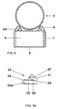
- dieselbe Leuchte im Querschnitt.
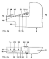
- Figur 4
- ein erstes Ausführungsbeispiel einer Hälfte eines Fassungsteils in Seitenansicht (a) und Draufsicht (b)
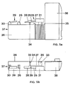
- Figur 5
- ein zweites Ausführungsbeispiel einer Hälfte eines Fassungsteils in Seitenansicht (a) und Draufsicht (b) sowie ein Detail in um 180° gedrehter Seitenansicht (c)
- Figur 6
- ein drittes Ausführungsbeispiel im Ausschnitt
- Im Innern des Trägerprofils 3 sind die notwendigen elektrischen Bauteile 6 (Vorschaltgerät, Starterelement, Temperatursicherung) untergebracht. Weiterhin weist die Leuchte einen Schalter 6a und eine elektrische Zuleitung 6b auf.
Die Lampe 2, deren Glaskolben einen Durchmesser von 26 mm aufweist, ist im rinnenförmigen Trägerprofil 3 geringfügig eingebettet, wobei die Seitenwände 7 des Trägerprofils entsprechend hochgezogen sind und in Randteilen 8 enden, die dachförmig zur Leuchtenachse hin abgewinkelt sind, wobei das freie Ende der beiden Randteile den Block der elektrischen Bauteile 6 von oben her klemmend gegen das Bodenteil 9 des Trägerprofils fixiert. - In den Figuren 1 und 2 ist eines der Fassungsteile 4 axial verschoben und bis zur ersten Raststufe aus dem Trägerprofil 3 herausgezogen, wodurch der eine Lampensockel 10 freigelegt ist und die Lampe gewechselt werden kann. Um den Lampenwechsel weiter zu vereinfachen, kann auch noch das gegenüberliegende Fassungsteil aus der gezeigten zweiten Raststufe mittels Drücken des Tastgriffs 11 des Fassungsteils 4 entriegelt und axial nach außen geschoben werden, bis es ebenfalls in die erste Raststufe einrastet. In beiden Raststufen bleiben die beiden Fassungsteile 4 mit dem Trägerprofil 3 verbunden. Die Fassungsteile 4 bestehen jeweils aus einer das Lampenende aufnehmenden Kappe 12 und einem seitlich daran angesetzten flacheren, im wesentlichen quaderförmigen Fußteil 13, welches in seinen Abmessungen dem rinnenförmigen Trägerprofil 3 angepaßt ist.
- Jeder Schalenhälfte - die zweite Schalenhälfte ist hierzu spiegelbildlich - (vgl. Fig. 4) ist an der Oberseite des Fußteils ein Rastverschluß, bestehend aus zwei axial hintereinander angeordneten Rastfederelementen 14, 15 angeformt. Das erste, unlösbare Rastfederelement 14 sitzt tangential an der Kuppe einer ersten Führungsrippe 16. Es besitzt die Form eines axial angeordneten, horizontalen Steges, der an seinem freien Ende, das zur Kappe 12 zeigt, leicht nach oben geschwungen ist, wobei die Dicke des Rastfederelementes 14 (1,2 mm) über die Länge des Steges konstant ist. Bei einer Gesamtlänge des Fußteils 13 von 45 mm beträgt die Länge des ersten Rastfederelements 14 etwa 13 mm. Die Führungsrippe, deren Kuppe ein schmaler Grat 17 aufgesetzt ist (s.u.), dient zur Halterung und Führung des Fußteils im Trägerprofil.
- Direkt hinter dem freien Ende des ersten Rastfederelements 14 sitzt eine zweite Führungsrippe 18 auf der Oberseite des Fußteils. Dieser ist auf halber Höhe als zweites, lösbares Rastfederelement 15 ein zur Kappe 12 gewandter schiefer Steg 19, der rampenartig mit ca. 10° Neigung ansteigt, angeformt. Die zweite Führungsrippe 18 besitzt ebenfalls einen schmalen Grat 20. Der Rampensteg 19, der etwa 17 mm lang ist, weist nur über etwa seine halbe Länge eine konstante Dicke (1,5 mm) auf. Dieser Bereich weist besonders gute Federeigenschaften auf. In seinem weiteren Verlauf verstärkt sich der Steg 19 an seiner Unterseite kontinuierlich auf etwa 3 mm Dicke. Ein ausgeprägtes Federn über die gesamte Länge wird dadurch vermieden, da dies das Verhältnis Tasthub zu Arbeitshub verschlechtern würde. Kappenseitig endet der Rampensteg 19 an seinem verdickten Ende mit einer Gegenrampe 21, deren Fügewinkel etwa 65° beträgt. Aufgrund dieses deutlich über 45° liegenden Fügewinkels ist es nicht möglich, das Fassungsteil 4 durch bloßes Schieben zu entrasten. Vielmehr erfolgt die Entriegelung durch ein Nach-unten-drücken des am zweiten Rastfederelement angebrachten Tastgriffs 11. Bei Drücken des von außen gut zugänglichen Tastgriffs 11 läßt sich das Fassungsteil 4 ohne Widerstand nach außen schieben. Um einen langen Hebelarm (30 mm) zu ermöglichen, ist der Tastgriff 11 zweckmäßig in unmittelbarer Nähe der Kappe 12 am seitlichen Rand des Fußteils 13 angeordnet. Er ist mit dem Rampensteg 19 durch ein Verlängerungsstück verbunden, das die Form einer Platte 22 besitzt, die seitlich am kappenseitigen Ende des Rampenstegs und am Tastgriff ansetzt. Die Platte 22 ist so breit, daß sie mit ihrem spiegelbildlichen Partner in Kontakt steht (vgl. Fig. 2) und an ihrer Breitseite Vorrichtungen 23, 23′ für das gegenseitige mechanische Befestigen, z.B. mittels einer mäanderförmigen Verkrallung, mit der Partnerplatte aufweist. Dadurch wird die Stabilität des zweiten Rastfederelements verbessert und weiterhin die Entriegelung beider spiegelbildlicher Rastfederelemente durch Bedienung nur eines Tastgriffs gewährleistet. Die Platte 22 verhindert außerdem ein seitliches Ausweichen des Tastgriffs quer zur Lampenachse.
- Die Funktionsweise des Rastverschlusses ist aus Figur 1 im einzelnen verständlich. Ein Rastanschlag 24, der die Form eines nach unten gerichteten Dreiecks mit abgestumpfter Spitze aufweist, ist jeweils am kappenseitigen Ende des Randteils 8 ausgebildet. Im montierten Zustand liegt die Gegenrampe 21 an der zur Leuchtenmitte gewandten Seite des Dreiecks an. Erst durch Drücken des Tasters (ca. 3 mm) nach unten (Tasthub) läßt sich die erste Stufe des Rastverschlusses entriegeln, wobei der dadurch bewirkte Hub an der Gegenrampe (Arbeitshub) ca. 1 mm beträgt. Das Fußteil läßt sich nach außen schieben, wobei die Spitze des Rastanschlags 24 in den Grat 20 einschneidet und dadurch Höhentoleranzen des Trägerprofils ausgleicht. Die Verschiebung ist so weit möglich, bis das aufwärts gerichtete Ende des ersten Rastfederelements sperrt (diese Stellung ist in Fig. 1 dargestellt), wobei die abgestumpfte Spitze des Rastanschlags genau auf der zweiten Führungsrippe zu liegen kommt und dadurch ein Wackeln der Fassung verhindert. Diese Sperre könnte nur - bedienungsfremd - mit Hilfe eines Werkzeugs überwunden werden.
- Während beim ersten Ausführungsbeispiel der Arbeitshub (1 mm) nur etwa ein Drittel des Tasthubs (3 mm) betrug, ist bei einem zweiten Ausführungsbeispiel (Fig. 5) das zweite Rastfederelement 25 so gestaltet, daß der Arbeitshub vergrößert ist (2 mm) und etwa dem Tasthub des Tastgriffs entspricht. Dies wird dadurch erzielt, daß der Hebelarm des lösbaren Rastfederelements 25 nicht mehr an der zweiten Führungsrippe 26 ansetzt, sondern mittels eines Querverbindungsteils an der Leuchtenachse. Das Verlängerungsstück ist als Verlängerungssteg 27 ausgeführt. Der Rampensteg 28 ist im Vergleich zum ersten Ausführungsbeispiel auf die kappenseitige Hälfte seiner Länge reduziert. Auch die kappenseitig ansetzende Gegenrampe 29, deren Fügewinkel ebenfalls bei etwa 65° liegt, ist etwas verkürzt. Der Verlängerungssteg 27, der den Rampensteg 28 mit einem breiten Tastgriff 31 verbindet, ist nur wenig breiter als der Rampensteg 28. Er ist seitlich etwas gegenüber dem Rampensteg und dem Tastgriff versetzt und verlängert im wesentlichen den Rampensteg horizontal über die Gegenrampe 29 hinaus. Zur Leuchtenachse hin ist jeweils in Höhe der Gegenrampe 29 und des Tastgriffs 31 ein Quersteg 32, 33 vom Verlängerungssteg aus zur Leuchtenachse gerichtet. Der besondere Clou dieses Ausführungsbeispiels ist, daß die Federarmlänge der Querstege 32, 33, die als Hebelarm (ca. 11 mm) wirkt, durch ein als Viertelbogen gestaltetes Ansatzstück 34, 35 mit verbreiterter Grundfläche 40a verlängert wird, das jeweils in unmittelbarer Nähe der Leuchtenachse an der Oberseite des Fußteils 36 jeder Schalenhälfte 37 angeformt ist. Dadurch wird bei vorgegebenem Hub die Biegebeanspruchung der Querstege 32, 33 erheblich reduziert.
- Die vom ersten Ausführungsbeispiel etwas abweichende Form des Fußteils 36 und der Kappe 38 jeder Schalenhälfte ist für die Erfindung ohne Bedeutung. Das erste, unlösbare Rastfederelement 39 ist wiederum ähnlich wie im ersten Ausführungsbeispiel gestaltet und an der ersten Führungsrippe 30 angesetzt.
- In einem dritten Ausführungsbeispiel (Fig. 6) ist das Rastfederelement mit einer Gegenrampe 40 ausgestattet, deren Fügewinkel 90° beträgt. Bei dieser Anordnung ist es besonders vorteilhaft, mehrere Gegenrampen (40′, 40˝) sägezahnartig hintereinander anzuordnen. Der Abstand der einzelnen Gegenrampen (40, 40′, 40˝) voneinander beträgt 1 bis 1,5 mm. Auf diese Weise kann bei gleicher Verschlußsicherheit der Ausgleich der Längentoleranzen für die elektrische Kontaktsicherheit der Lampe an der Fassung erweitert werden (ca. 2,5 mm). In diesem Fall wird auch die abgestumpfte Spitze des Rastanschlags durch eine oder mehrere sägezahnartige Spitzen 41 ersetzt. Diese Anordnung ist sowohl für längsgerichtete als auch für quergerichtete Hebelarme geeignet.
- Statt mit angeformten Kunststoffteilen kann die Erfindung auch mittels eines metallischen Stanzblechteils, das auf der Oberseite des Fußteils aufliegt, ausgeführt sein. Die paarig angelegten Rastfederelemente sind seitlich am Blechteil ausgestanzt und gebogen, um eine Federwirkung zu erzeugen.
- Die näher erläuterten Ausführungsbeispiele aus Kunststoff haben jedoch erhebliche fertigungstechnische und bedienungstechnische Vorteile. Die Erfindung ist nicht auf die konkret dargestellte Leuchte beschränkt, sondern läßt sich auch auf andere mit stabförmigen Lampen bestückte Leuchten oder auch Leuchtstofflampen-Sets anwenden.
Claims (16)
- Leuchte bestehend aus einer stabförmigen Leuchtstofflampe (2), und einem eine Leuchtenachse definierenden langgestreckten Trägerprofil (3), wobei die Leuchtstofflampe an ihren Stirnseiten in zwei Fassungsteilen (4) kontaktierend gehaltert ist, welche jeweils ein Fußteil (13; 36) zum Einschieben an den beiden Enden des Trägerprofils (3) aufweisen, wobei jedes Fußteil (13; 36) mit einem zweistufigen Rastverschluß ausgestattet ist, bestehend aus zwei axial hintereinander angeordneten Rastfederelementen (14, 15; 39, 25), die mit einem Rastanschlag (24) am Trägerprofil (3) so zusammenwirken, daß das eine Element (14; 39) unlösbar und das andere Element (15; 25) lösbar verrasten kann, dadurch gekennzeichnet, daß das lösbare Rastfederelement (15; 25) einen in axialer Richtung verlaufenden Steg (19; 28), der rampenartig ansteigt, aufweist, im folgenden Rampensteg genannt, der an seinem von der Leuchtenmitte abgewandten Ende eine Gegenrampe (21; 29) besitzt, deren Fügewinkel größer als 45° ist, wobei dem Rampensteg (19; 28) in Richtung zum Leuchtenende ein Verlängerungsstück (22; 27) angefügt ist, das mit einem von außen zugänglichen Tastergriff (11; 31) zum Entriegeln ausgestattet ist.
- Leuchte nach Anspruch 1, dadurch gekennzeichnet, daß zumindest das lösbare Rastfederelement (15; 25) des Rastverschlusses aus Kunststoffteilen besteht, die an der der Lampe (2) zugewandten Oberseite des Fußteils (13; 36) angeformt sind.
- Leuchte nach Anspruch 1, dadurch gekennzeichnet, daß der Fügewinkel ca. 90° beträgt.
- Leuchte nach Anspruch 2, dadurch gekennzeichnet, daß die Dicke des Rampenstegs (19) zum Leuchtenende hin verstärkt ist.
- Leuchte nach Anspruch 1, dadurch gekennzeichnet, daß der Fügewinkel ca. 65° beträgt.
- Leuchte nach Anspruch 1, dadurch gekennzeichnet, daß der Rastverschluß aus paarig angelegten, im wesentlichen spiegelbildlichen Einzelteilen (Partnerteil) besteht.
- Leuchte nach Anspruch 6, dadurch gekennzeichnet, daß das Verlängerungsstück eine Platte (22) ist, die seitlich am Rampensteg (19) ansetzt und sich bis zur Leuchtenachse erstreckt und mit Vorrichtungen (23) zum Verankern am spiegelbildlichen Partnerteil ausgestattet ist.
- Leuchte nach Anspruch 2 oder 6, dadurch gekennzeichnet, daß der Rampensteg und das Verlängerungsstück einen in Richtung der Längsachse ausgerichteten federnden Hebelarm bilden, indem der Rampensteg an der Oberseite des Fußteils (13) ansetzt.
- Leuchte nach Anspruch 8, dadurch gekennzeichnet, daß der Rampensteg an einer kuppenförmigen Führungsrippe (18) ansetzt, die an der Oberseite des Fußteils (13) ausgebildet ist.
- Leuchte nach Anspruch 2, dadurch gekennzeichnet, daß der Rampensteg und das Verlängerungsstück einen quer zur Längsachse ausgerichteten federnden Hebelarm bilden, indem das Verlängerungsstück über ein Querverbindungsteil in der Nähe der Leuchtenachse an der Oberseite des Fußteils angeformt ist.
- Leuchte nach Anspruch 10, dadurch gekennzeichnet, daß das Querverbindungsteil durch zwei Querstege (32, 33) gebildet wird.
- Leuchte nach Anspruch 10, dadurch gekennzeichnet, daß das Querverbindungsteil ein gebogenes Teilstück aufweist, das den federnden Hebelarm verlängert.
- Leuchte nach Anspruch 12, dadurch gekennzeichnet, daß das gebogene Teilstück ein als Viertelbogen ausgebildetes Ansatzstück (34, 35) an der Oberseite des Fußteils ist.
- Leuchte nach Anspruch 1, dadurch gekennzeichnet, daß der Fügewinkel ca. 90° beträgt.
- Leuchte nach Anspruch 14, dadurch gekennzeichnet, daß mindestens eine weitere Gegenrampe (40', 40'') hinter der ersten Gegenrampe (40) angeordnet ist.
- Leuchte nach Anspruch 15, dadurch gekennzeichnet, daß der Rastanschlag eine oder mehrere an den Gegenrampen eingreifende sägezahnartige Spitzen (41) aufweist.
Applications Claiming Priority (2)
| Application Number | Priority Date | Filing Date | Title |
|---|---|---|---|
| DE8903302U DE8903302U1 (de) | 1989-03-16 | 1989-03-16 | Leuchte |
| DE8903302U | 1989-03-16 |
Publications (2)
| Publication Number | Publication Date |
|---|---|
| EP0388678A1 EP0388678A1 (de) | 1990-09-26 |
| EP0388678B1 true EP0388678B1 (de) | 1994-06-29 |
Family
ID=6837202
Family Applications (1)
| Application Number | Title | Priority Date | Filing Date |
|---|---|---|---|
| EP90104017A Expired - Lifetime EP0388678B1 (de) | 1989-03-16 | 1990-03-01 | Leuchte |
Country Status (4)
| Country | Link |
|---|---|
| EP (1) | EP0388678B1 (de) |
| AT (1) | ATE108008T1 (de) |
| DE (2) | DE8903302U1 (de) |
| ES (1) | ES2056271T3 (de) |
Families Citing this family (2)
| Publication number | Priority date | Publication date | Assignee | Title |
|---|---|---|---|---|
| ES2259351T3 (es) * | 2002-05-10 | 2006-10-01 | Goodrich Lighting Systems Gmbh | Lampara para un vehiculo, en especial lampara de lectura para un avion. |
| US6997583B2 (en) | 2002-05-10 | 2006-02-14 | Goodrich Hella Aerospace Lighting Systems Gmbh | Lamp for a vehicle, in particular reading lamp for an aircraft |
Family Cites Families (3)
| Publication number | Priority date | Publication date | Assignee | Title |
|---|---|---|---|---|
| NL6912548A (de) * | 1968-08-27 | 1970-03-03 | ||
| DE2134339A1 (de) * | 1971-07-09 | 1973-01-18 | Vossloh Werke Gmbh | Kopfstueckfassung fuer lichtleisten |
| DE2853854A1 (de) * | 1978-12-13 | 1980-07-03 | Patra Patent Treuhand | Leuchtstofflampen-set |
-
1989
- 1989-03-16 DE DE8903302U patent/DE8903302U1/de not_active Expired
-
1990
- 1990-03-01 ES ES90104017T patent/ES2056271T3/es not_active Expired - Fee Related
- 1990-03-01 DE DE59006270T patent/DE59006270D1/de not_active Expired - Lifetime
- 1990-03-01 AT AT90104017T patent/ATE108008T1/de not_active IP Right Cessation
- 1990-03-01 EP EP90104017A patent/EP0388678B1/de not_active Expired - Lifetime
Also Published As
| Publication number | Publication date |
|---|---|
| EP0388678A1 (de) | 1990-09-26 |
| DE8903302U1 (de) | 1989-05-03 |
| ES2056271T3 (es) | 1994-10-01 |
| DE59006270D1 (de) | 1994-08-04 |
| ATE108008T1 (de) | 1994-07-15 |
Similar Documents
| Publication | Publication Date | Title |
|---|---|---|
| DE2115728C3 (de) | Elektrischer Schalter | |
| EP0225490A2 (de) | Temperaturbegrenzer | |
| WO2016079077A1 (de) | Federkraftklemme | |
| EP0582258B1 (de) | Befestigungsvorrichtung | |
| WO1988000389A1 (fr) | Commutateur electrique | |
| DE3230414C3 (de) | ||
| DE102006024994B3 (de) | Elektronischer Schalter | |
| EP0955692A2 (de) | Anschlussklemme mit Kniehebelbetätigung | |
| EP0450366A1 (de) | Druckknopfbetätigter Schutzschalter | |
| DE1924701A1 (de) | Thermisch ansprechender Schnappschalter | |
| DE3724736C2 (de) | Elektrischer Schalter, insbesondere für Kraftfahrzeuge | |
| DE2416969C2 (de) | Druckknopfschalter | |
| EP0388678A1 (de) | Leuchte | |
| CH671648A5 (en) | Electric contact device for keyboard switch - uses double armed contact element between pushbutton operating element and fixed counter contact pin | |
| DE4319615A1 (de) | Elektrischer Schalter, insbesondere für eine elektrische Zahnbürste | |
| EP2250658A1 (de) | Elektrische installationsvorrichtung, wie taster oder tastschalter | |
| DE3940285C2 (de) | ||
| DE60308551T2 (de) | Aus elastischem material bestehendes befestigungsglied | |
| DE2827854C2 (de) | Elektrischer Wippenschalter | |
| EP0548477B1 (de) | Tastschalter mit Ansatz | |
| DE19537253C2 (de) | Kippschalter | |
| EP0693760A1 (de) | Niederspannungsschaltgerät | |
| EP0369221B1 (de) | Elektrischer Schalter für ein elektrisches Handwerkzeug | |
| DE2521789A1 (de) | Potentiometer | |
| EP0170958B1 (de) | Piezoelektrisches Relais |
Legal Events
| Date | Code | Title | Description |
|---|---|---|---|
| PUAI | Public reference made under article 153(3) epc to a published international application that has entered the european phase |
Free format text: ORIGINAL CODE: 0009012 |
|
| AK | Designated contracting states |
Kind code of ref document: A1 Designated state(s): AT BE CH DE ES FR GB IT LI NL SE |
|
| 17P | Request for examination filed |
Effective date: 19901026 |
|
| 17Q | First examination report despatched |
Effective date: 19930205 |
|
| GRAA | (expected) grant |
Free format text: ORIGINAL CODE: 0009210 |
|
| AK | Designated contracting states |
Kind code of ref document: B1 Designated state(s): AT BE CH DE ES FR GB IT LI NL SE |
|
| REF | Corresponds to: |
Ref document number: 108008 Country of ref document: AT Date of ref document: 19940715 Kind code of ref document: T |
|
| REF | Corresponds to: |
Ref document number: 59006270 Country of ref document: DE Date of ref document: 19940804 |
|
| ITF | It: translation for a ep patent filed | ||
| REG | Reference to a national code |
Ref country code: ES Ref legal event code: FG2A Ref document number: 2056271 Country of ref document: ES Kind code of ref document: T3 |
|
| GBT | Gb: translation of ep patent filed (gb section 77(6)(a)/1977) |
Effective date: 19940907 |
|
| ET | Fr: translation filed | ||
| EAL | Se: european patent in force in sweden |
Ref document number: 90104017.0 |
|
| PLBE | No opposition filed within time limit |
Free format text: ORIGINAL CODE: 0009261 |
|
| STAA | Information on the status of an ep patent application or granted ep patent |
Free format text: STATUS: NO OPPOSITION FILED WITHIN TIME LIMIT |
|
| 26N | No opposition filed | ||
| PGFP | Annual fee paid to national office [announced via postgrant information from national office to epo] |
Ref country code: GB Payment date: 19960220 Year of fee payment: 7 |
|
| PGFP | Annual fee paid to national office [announced via postgrant information from national office to epo] |
Ref country code: AT Payment date: 19960223 Year of fee payment: 7 |
|
| PGFP | Annual fee paid to national office [announced via postgrant information from national office to epo] |
Ref country code: BE Payment date: 19960319 Year of fee payment: 7 |
|
| PGFP | Annual fee paid to national office [announced via postgrant information from national office to epo] |
Ref country code: SE Payment date: 19960320 Year of fee payment: 7 |
|
| PGFP | Annual fee paid to national office [announced via postgrant information from national office to epo] |
Ref country code: NL Payment date: 19960328 Year of fee payment: 7 |
|
| PG25 | Lapsed in a contracting state [announced via postgrant information from national office to epo] |
Ref country code: GB Effective date: 19970301 Ref country code: AT Effective date: 19970301 |
|
| PG25 | Lapsed in a contracting state [announced via postgrant information from national office to epo] |
Ref country code: SE Effective date: 19970302 |
|
| PG25 | Lapsed in a contracting state [announced via postgrant information from national office to epo] |
Ref country code: BE Effective date: 19970331 |
|
| BERE | Be: lapsed |
Owner name: PATENT-TREUHAND-G.- FUR ELEKTRISCHE GLUHLAMPEN M. Effective date: 19970331 |
|
| PG25 | Lapsed in a contracting state [announced via postgrant information from national office to epo] |
Ref country code: NL Effective date: 19971001 |
|
| GBPC | Gb: european patent ceased through non-payment of renewal fee |
Effective date: 19970301 |
|
| NLV4 | Nl: lapsed or anulled due to non-payment of the annual fee |
Effective date: 19971001 |
|
| EUG | Se: european patent has lapsed |
Ref document number: 90104017.0 |
|
| PGFP | Annual fee paid to national office [announced via postgrant information from national office to epo] |
Ref country code: ES Payment date: 20050316 Year of fee payment: 16 |
|
| PGFP | Annual fee paid to national office [announced via postgrant information from national office to epo] |
Ref country code: FR Payment date: 20050331 Year of fee payment: 16 |
|
| PGFP | Annual fee paid to national office [announced via postgrant information from national office to epo] |
Ref country code: CH Payment date: 20050607 Year of fee payment: 16 |
|
| PG25 | Lapsed in a contracting state [announced via postgrant information from national office to epo] |
Ref country code: ES Free format text: LAPSE BECAUSE OF NON-PAYMENT OF DUE FEES Effective date: 20060302 |
|
| PG25 | Lapsed in a contracting state [announced via postgrant information from national office to epo] |
Ref country code: CH Free format text: LAPSE BECAUSE OF NON-PAYMENT OF DUE FEES Effective date: 20060331 Ref country code: LI Free format text: LAPSE BECAUSE OF NON-PAYMENT OF DUE FEES Effective date: 20060331 |
|
| PGFP | Annual fee paid to national office [announced via postgrant information from national office to epo] |
Ref country code: IT Payment date: 20060331 Year of fee payment: 17 |
|
| REG | Reference to a national code |
Ref country code: CH Ref legal event code: PL |
|
| REG | Reference to a national code |
Ref country code: FR Ref legal event code: ST Effective date: 20061130 |
|
| REG | Reference to a national code |
Ref country code: ES Ref legal event code: FD2A Effective date: 20060302 |
|
| PG25 | Lapsed in a contracting state [announced via postgrant information from national office to epo] |
Ref country code: FR Free format text: LAPSE BECAUSE OF NON-PAYMENT OF DUE FEES Effective date: 20060331 |
|
| PGFP | Annual fee paid to national office [announced via postgrant information from national office to epo] |
Ref country code: DE Payment date: 20090518 Year of fee payment: 20 |
|
| PG25 | Lapsed in a contracting state [announced via postgrant information from national office to epo] |
Ref country code: IT Free format text: LAPSE BECAUSE OF NON-PAYMENT OF DUE FEES Effective date: 20070301 |
|
| PG25 | Lapsed in a contracting state [announced via postgrant information from national office to epo] |
Ref country code: DE Free format text: LAPSE BECAUSE OF EXPIRATION OF PROTECTION Effective date: 20100301 |