EP0388643A2 - Leuchtsymbolkörper - Google Patents
Leuchtsymbolkörper Download PDFInfo
- Publication number
- EP0388643A2 EP0388643A2 EP90103237A EP90103237A EP0388643A2 EP 0388643 A2 EP0388643 A2 EP 0388643A2 EP 90103237 A EP90103237 A EP 90103237A EP 90103237 A EP90103237 A EP 90103237A EP 0388643 A2 EP0388643 A2 EP 0388643A2
- Authority
- EP
- European Patent Office
- Prior art keywords
- plate
- body according
- housing
- symbol
- luminous
- Prior art date
- Legal status (The legal status is an assumption and is not a legal conclusion. Google has not performed a legal analysis and makes no representation as to the accuracy of the status listed.)
- Granted
Links
Images
Classifications
-
- G—PHYSICS
- G09—EDUCATION; CRYPTOGRAPHY; DISPLAY; ADVERTISING; SEALS
- G09F—DISPLAYING; ADVERTISING; SIGNS; LABELS OR NAME-PLATES; SEALS
- G09F13/00—Illuminated signs; Luminous advertising
- G09F13/04—Signs, boards or panels, illuminated from behind the insignia
- G09F13/0404—Signs, boards or panels, illuminated from behind the insignia the light source being enclosed in a box forming the character of the sign
Definitions
- the present invention relates to a luminous symbol body, in particular for outdoor advertising lettering.
- outdoor advertising lettering which consist of letter casings, which are designed to be opaque and whose light sources integrated in the casing emit light to the rear.
- the wall is illuminated, so that the letters emerge darkly from the brightly illuminated wall surface to which they are attached.
- the present invention has for its object to improve indirectly illuminated luminous symbol bodies of the type described above in such a way that a uniformly bright background is always created in the area of the symbol contours, regardless of the place of attachment, so that a uniform appearance can be achieved regardless of the background of the external advertising lettering.
- Preferred embodiments of the luminous symbol body according to the invention according to claim 1 are characterized in the subclaims.
- the luminous symbol body according to the invention is based on the principle of closing the back of the symbol with a transparent plate which protrudes by a certain amount at the symbol peripheral edges and in particular to design this plate at its edges so that light emerging from the plate is emitted forward to the viewer of the illuminated lettering without that another backscattering background would be required.
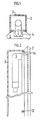
- FIGS. 1 to 4 represents, as a simple exemplary embodiment, a cuboid body which can be used as "I" or as a hyphen in a light lettering.
- Figure 1 shows a light source (1), which is housed for the most part in a housing (3) which, seen in section, consists of 3 walls, 2 side walls and a bottom, which are glued together.
- the housing forms the symbol body, e.g. a letter.
- the housing walls are made of acrylic glass, which is lacquered white light-proof on the inside. Of course, housings made of metal or other materials can also be used, and light-tightness may also not be necessary in certain areas to achieve certain effects.
- the housing base can be flat as shown, but it can also have any desired shape, e.g. have a roof shape or other profiles.
- the housing (3) is closed by a plate (2), into which a channel (4) is incorporated, which receives part of the light source (1).
- a shoulder (9) of the plate (2) protrudes into the interior of the housing (3), which ends in a form-fitting manner on the edge of the housing (3) with the inside of the side walls of the housing (3).
- the plate (2) and the housing (3) are fastened to one another using countersunk screws (12).
- the shoulders can be molded in one piece from the plate (2), they can also be attached later as glued-on tongues.
- FIG. 1 It can be seen in FIG. 1 that the areas of the plate (2) projecting beyond the side walls of the housing (3) are chamfered at an angle of 45 ° with respect to the plate surface.
- a variant is shown on the left, in which the lower edge is also bevelled by 45 °.
- the aim of this bevel is to allow light propagating in the plate to emerge from the plate body at certain angles in the direction of the viewer of the illuminated lettering, so that an optimum of light intensity can clearly show the contour of the symbol body.
- the plate (2) is made of clear acrylic glass, but there are also other materials, such as Quartz glass or the like is conceivable.
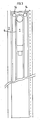
- Figure 2 shows the symbol body of Figure 1 from the side, partially cut longitudinally.
- the light source used in FIG. 1 is a fluorescent tube, which is bent at its ends into the inside of the housing in a U-shape, so that the part of the fluorescent tube containing the fluorescent substance can be guided up to close to the upper edge of the housing.
- the electrode of the fluorescent tube is covered by an electrode cover which is fastened to the plate 2 and which can be designed in the form of a grid, e.g. in the form of a perforated plate, protected from external influences. Furthermore, glass holder pins are provided for holding the tube - likewise not shown - which engage in bores on both sides of the groove and span part of the tube.
- the acrylic glass plate (2) shows the edge grinding provided in Figure 1 on the left edge.
- Figure 3 shows the light symbol body partially cut in plan view.
- the channel (4) is milled into the plate (2) and follows the contours of the fluorescent tube (1) with essentially constant play.
- openings (14) are provided in the interior of the housing for the power supply for the fluorescent tube (1).
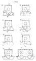
- FIGS. 4a-h show various shaping options for the edge regions of the plate (2) which project beyond the side walls of the housing (3).
- FIG. 4a shows the simplest case in which the plate (2) is only cut perpendicular to the main surfaces of the plate, a constant protrusion being maintained relative to the side walls of the housing (3).
- the light emitted by the light source (1) enters the transparent plate (2) on the side walls of the channel (4) by refraction of the beam path, where a large part of the light is reflected on the rear side (15) of the plate (2) .
- the reflected light occurs partly on the parallel to the side walls of the housing (3) Cut surfaces of the plate and partly in the area of the peripheral edge (5) of the plate (2) with renewed refraction.
- the variant shown in Figure 4b has a groove (8) in the region of the peripheral edge of the plate (2), which has the effect that the light emerging in the direction of the viewer is guided more along the side surfaces of the housing (3).
- a coating of highly reflective material is attached to the rear (15) of the plate (2) to increase the reflection.
- This can be a foil made of aluminum or also a highly reflective layer made of aluminum, silver or the like which is attached by chemical means or by evaporation.
- Figure 4d also shows 2 variants in which the back of the plate is either concave or convex.
- the concave curvature shown in the left half causes a further fanning out of the light directed towards the front, whereas the convex bottom shape on the right side tends to concentrate the light thrown forward.
- Figures 4 e and f have roundings (7) in the peripheral edge regions of the plate (2), which can be attached either to the upper and to the lower edge or only to the upper edge.
- This edge design in the form of cylindrical lenses also results in a specific beam guidance, which leads here to the fact that the light coupled into the plate (2) is perceived by the viewer as a clearly delimited narrow light strip which surrounds the silhouette of the symbol body.
- 4g shows a plate 2 with a trapezoidal cross section, the longest edge describing the surface facing the housing 3.
- the angle of inclination ⁇ of the peripheral edge with respect to the above-mentioned surface is 60 °. With the plastic material used, this value results in very favorable light beam guidance approximately parallel to the housing side walls towards the viewer. In certain applications, other angles of inclination may also be considered. For example, a smaller angle of inclination at the bottom edge of the symbol is advantageous if the symbol bodies are arranged far above the eye level of viewers in order to cause light reflection obliquely downwards.
- Channel 4 is milled here with partly sloping side walls. The slightly roughened surface created by milling is advantageous for coupling light from the tube into the plastic material and is therefore left unchanged.
- the light coupled into the plastic material from the tube is reflected at the peripheral edge. Most rays hit the inclined edge surface at an angle greater than or equal to the angle of total reflection. This results in an optimal radiation of the light rays towards the viewer, whereby the contours of the luminous symbol body come out sharply.
- the channel 4 is widened at its ends, in particular in the case of very slim symbol bodies, for example the letters "I”, “H”, “N” etc., transversely to its longitudinal extent towards the edges of the symbol body.
- This expansion can be essentially triangular in plan view, with the base parallel to the narrow end of a symbol body. It may also be sufficient to mill a narrow groove that "T" -shaped end of channel.
- the rough milled channel walls diffuse the light from the light source evenly onto the inclined edge surfaces of the symbol body at the channel ends, so that there is approximately a uniform light distribution around the symbol body.
- Fig. 4h shows a wider symbol body, in the plate two channels are incorporated for receiving fluorescent tubes. This ensures that the distance between the fluorescent tube and the edge to be illuminated by it is not too great. On the other hand, a uniform illumination of the base is ensured in the case of symbol bodies with an at least partially transparent housing base.
Landscapes
- Physics & Mathematics (AREA)
- General Physics & Mathematics (AREA)
- Engineering & Computer Science (AREA)
- Theoretical Computer Science (AREA)
- Illuminated Signs And Luminous Advertising (AREA)
- Organic Low-Molecular-Weight Compounds And Preparation Thereof (AREA)
Abstract
Schriftzüge, die mit den erfindungsgemäßen Leuchtsymbolkörpern erstellt werden, können ohne Rücksicht auf den Hintergrund angebracht werden und bewirken eine indirekte Beleuchtung des Schriftzuges in stets gleichbleibender Weise.
Description
- Die vorliegende Erfindung betrifft einen Leuchtsymbolkörper, insbesondere für Außenwerbungsschriftzüge.
- Gewerbebetriebe aus allen Branchen benutzen seit sehr langer Zeit leuchtende Hinweisschriftzüge und Leuchtreklamen, um auf sich aufmerksam zu machen. Dabei standen nach dem Aufkommen von Leuchtstoffröhren Schriftzüge im Vordergrund, die unmittelbar durch eine Aneinanderreihung von zu Buchstaben geformtem Leuchtstoffröhren gebildet wurden. Solche Schriften haben den Vorteil weithin sichtbar zu sein und eine starke Leuchtkraft zu haben. Als nachteilig wird empfunden, daß ein bestimmtes Schriftbild oder Firmenzeichen mit scharfen Konturen nur unvollkommen zum Ausdruck gebracht werden können. Ferner läßt sich in ungünstigen Fällen ein aus solchen Röhren gebildeter Schriftzug am hellichten Tage und im ausgeschalteten Zustand aufgrund mangelnden Kontrastes zu seinem Hintergrund nur schlecht erkennen.
- Um diese Nachteile zu vermeiden ist man dazu übergegangen zum Beispiel Buchstaben eines Außenwerbungsschriftzuges als einzelne, separate Gehäuse auszubilden, die jeweils eine Lichtquelle aufnehmen und von denen wenigstens die zum Betrachter gerichtete Seite transparent, und gegebenenfalls in einer gewünschten Farbe getönt ist. Die Darstellung von Schriftzügen mit scharfen Konturen gelingt auf diese Weise schon sehr viel besser als bei den zuerst genannten Beispielen, einige nachteilige Effekte können jedoch auch auf diese Art nicht vermieden werden. So kann beispielsweise das Erscheinungsbild eines Schriftzuges bzw. einer Leuchtreklame am hellichten Tage im ausgeschalteten Zustand und in der Nacht im eingeschalteten Zustand stark unterschiedlich sein. Andererseits kann in sorgfältig gestalteten Umfeldern eine grell strahlende Leuchtreklame als zu aufdringlich empfunden werden. Aus diesem Grunde wurden Außenwerbungsschriftzüge entwickelt, die aus Buchstabengehäusen bestehen, die lichtundurchlässig gestaltet sind und deren in die Gehäuse integrierte Lichtquellen Licht nach hinten abstrahlen. Auf diese Weise wird bei einer Anbringung von Schriftzügen in einem bestimmten Abstand von einer hellen Wandfläche die Wand beleuchtet, so daß die Buchstaben dunkel gegenüber der hell erleuchteten Wandfläche, an der sie angebracht sind, hervortreten.
- Diese Lösung ist stark von der Beschaffenheit der Wand abhängig, an der ein solcher Schriftzug angebracht werden soll. Das Erscheinungsbild eines solche Werbeschriftzuges hängt von den Rückstreueigenschaften des Hintergrundes ab. Soll z.B. bei einem Gewerbebetrieb ein einheitliches Erscheinungsbild für alle Filialen erzielt werden, so ist dies problematisch. Je nach den vorgefundenen räumlichen Gegebenheiten ist es denkbar, daß ein solcher Schriftzug auf ein Giebeldach oder in anderer Weise mehr oder weniger freistehend angebracht werden muß, so daß eine reflektierende bzw. rückstreuende Wand hinter dem Schriftzug wegfällt, die durch die Kontrastwirkung den Schriftzug erst sichtbar macht.
- Der vorliegenden Erfindung liegt die Aufgabe zugrunde, indirekt beleuchtete Leuchtsymbolkörper der oben geschilderten Art dahingehend zu verbessern, daß unabhängig vom Anbringungsort stets ein gleichförmig heller Hintergrund im Bereich der Symbolkonturen geschaffen wird, so daß ein einheitliches Erscheinungsbild unabhängig vom Hintergrund des Außenwerbungsschriftzuges erzielt werden kann.
- Diese Aufgabe wird mit den Merkmalen des Anspruchs 1 gelöst.
- In den Unteransprüchen sind bevorzugte Ausgestaltungen des erfindungsgemäßen Leuchtsymbolkörpers nach Anspruch 1 gekennzeichnet.
- Dem erfindungsgemäßen Leuchtsymbolkörper liegt das Prinzip zugrunde die Symbolrückseite mit einer transparenten Platte abzuschließen, die an den Symbolumfangsrändern um einen bestimmten Betrag übersteht und diese Platte insbesondere an ihren Rändern so auszugestalten, daß aus der Platte austretendes Licht nach vorne zum Betrachter der Leuchtschrift abgestrahlt wird, ohne daß es dazu eines weiteren rückstreuenden Hintergrundes bedürfte.
- Im folgenden wird die Erfindung anhand der Beschreibung von Ausführungsbeispielen, die nicht einschränkend zu verstehen sind mit Bezug auf die Zeichnung näher erläutert. Es zeigen:
- Fig. 1 einen neuerungsgemäßen Leuchtsymbolkörper im Schnitt;
- Fig. 2 den Leuchtsymbolkörper von Fig. 1 teilweise im Längsschnitt;
- Fig. 3 eine teilweise geschnittene Draufsicht auf den Leuchtsymbolkörper gemäß Fig. 1; und
- Fig. 4a-h verschiedene Varianten der Ausgestaltung des Randbereiches der transparenten Platte.
- Das in den Figuren 1 bis 4 dargestellte Leuchtsymbol stellt als einfaches Ausführungsbeispiel einen quaderförmigen Körper dar, der als "I" oder als ein Bindestrich in einer Leuchtschrift Verwendung finden kann. Figur 1 zeigt eine Lichtquelle (1), die zum überwiegenden Teil in einem Gehäuse (3) untergebracht ist, das im Schnitt gesehen aus 3 Wänden, 2 Seitenwänden und einem Boden besteht, die miteinander verklebt sind. Das Gehäuse bildet den Symbolkörper, z.B. einen Buchstaben. Die Gehäusewände bestehen aus Acrylglas, das hier innen weiß lichtdicht ablackiert ist. Es können selbstverständlich auch Gehäuse aus Metall oder anderen Werkstoffen Verwendung finden, und auch die Lichtdichtheit kann zur Erzielung bestimmter Effekte bereichsweise nicht erforderlich sein. Der Gehäuseboden kann, wie gezeigt, plan sein, er kann aber auch jede gewünschte Form, z.B. eine Dachform oder andere Profile haben.
- Das Gehäuse (3) wird durch eine Platte (2) abgeschlossen, in die ein Kanal (4) eingearbeitet ist, der einen Teil der Lichtquelle (1) in sich aufnimmt.
- In das Innere des Gehäuses (3) ragt eine Schulter (9) der Platte (2), die formschlüssig am Rand des Gehäuses (3) mit der Innenseite der Seitenwände des Gehäuses (3) abschließt. Im Überlappungsbereich der Seitenwände des Gehäuses (3) und der Schulter werden die Platte (2) und das Gehäuse (3) über Senkkopfschrauben (12) ineinander befestigt. Die Schultern können einstückig aus der Platte (2) herausgeformt sein, sie können auch als aufgeklebte Zungen später angebracht werden.
- Man erkennt in Figur 1, daß die über die Seitenwände des Gehäuses (3) überstehenden Bereiche der Platte (2) unter einem Winkel von 45° gegenüber der Plattenoberfläche abgeschrägt sind. Auf der linken Seite ist eine Variante gezeigt, in der auch der untere Rand um 45° abgeschrägt ist. Ziel dieser Abschrägung ist es, daß sich in der Platte fortpflanzendes Licht unter bestimmten Winkeln in Richtung auf den Betrachter der Leuchtschrift aus dem Plattenkörper austreten zu lassen, so daß ein Optimum an Lichtintensität die Kontur des Symbolkörpers deutlich hervortreten läßt.
- Weitere Varianten der Gestaltung des Randbereiches der Platte (2) werden in Figur 4 vorgestellt. Die Platte (2) ist hier aus glasklarem Acrylglas gefertigt, es sind jedoch auch andere Werkstoffe, wie z.B. Quarzglas oder dergleichen denkbar.
- Figur 2 zeigt den Symbolkörper nach Figur 1 von der Seite, teilweise längsgeschnitten. Die verwendete Lichtquelle in 1 ist eine Leuchtstoffröhre, die an ihren Enden U-förmig in das Gehäuseinnere hinein umgebogen ist, damit der den Leuchtstoff enthaltende Teil der Leuchtstoffröhre bis nahe an den oberen Rand des Gehäuses geführt werden kann.
- Die Elektrode der Leuchtstoffröhre wird durch eine an der Platte 2 befestigte Elektrodenabdeckung, die gitterförmig gestaltet sein kann, z.B. in Form eines Lochbleches, vor äußeren Einwirkungen geschützt. Ferner sind zur Halterung der Röhre - ebenfalls nicht gezeigte - Glashalterungsstifte vorgesehen, die in Bohrungen zu beiden Seiten der Nut eingreifen und einen Teil der Röhre umspannen.
- Die Acrylglasplatte (2) zeigt den in Figur 1 am linken Rand vorgesehenen Kantenschliff.
- Figur 3 zeigt den Leuchtsymbolkörper teilweise geschnitten in Draufsicht. Der Kanal (4) ist in die Platte (2) eingefräst und folgt mit im wesentlichen konstanten Spiel den Konturen der Leuchtstoffröhre (1). An einem Ende des quaderförmigen Symbolkörpers sind in das Gehäuseinnere reichende Öffnungen (14) für die Stromzuführung für die Leuchtstoffröhre (1) vorgesehen.
- In den Figuren 4a-h sind verschiedene Formgebungsmöglichkeiten für die über die Seitenwände des Gehäuses (3) überstehenden Randbereiche der Platte (2) gezeigt. Figur 4a zeigt dabei den einfachsten Fall, in dem die Platte (2) lediglich senkrecht zu den Hauptflächen der Platte zugeschnitten ist, wobei ein konstanter Überstand gegenüber den Seitenwänden des Gehäuses (3) eingehalten wird.
- Das von der Lichtquelle (1) abgestrahlte Licht tritt an den Seitenwänden des Kanals (4) unter Brechung des Strahlengangs in die transparente Platte (2) ein, wo ein großer Teil des Lichtes an der Rückseite (15) der Platte (2) reflektiert wird. Das reflektierte Licht tritt zum Teil an den zu den Seitenwänden des Gehäuses (3) parallelen Schnittflächen der Platte und zum Teil im Bereich des Umfangsrandes (5) der Platte (2) unter erneuter Brechung aus. Die in Figur 4b gezeigt Variante weist eine Nut (8) im Bereich des Umfangsrandes der Platte (2) auf, die den Effekt hat, daß das in Richtung des Betrachters austretende Licht stärker entlang der Seitenflächen des Gehäuses (3) geführt wird. Die Ausführungsformen nach den Figuren 4 c und d haben die gegenteilige Wirkung, d.h. es wird eine Auffächerung des in Richtung auf den Betrachter reflektierten Lichtes unter einem größeren Öffnungswinkel erwünscht. In Figur 4c ist zur Erhöhung der Reflexion an der Rückseite (15) der Platte (2) eine Beschichtung aus hochreflektierendem Material angebracht. Dies kann eine Folie aus Aluminium sein oder auch eine auf chemischem Wege oder durch Verdampfen angebrachte stark reflektierende Schicht aus Aluminium, Silber oder dergleichen.
- Figur 4d zeigt darüber hinaus 2 Varianten, bei denen die Plattenrückseite entweder konkav oder konvex gewölbt ist. Die in der linken Hälfte dargestellte konkave Wölbung bewirkt eine weitere Auffächerung des nach vorne geführten Lichtes, wohingegen die konvexe Bodenformung auf der rechten Seite eher zu einer Bündelung des nach vorne geworfenen Lichtes führt.
- Die Figuren 4 e und f weisen in den Umfangsrandbereichen der Platte (2) Abrundungen (7) auf, die entweder sowohl am oberen als auch am unteren Rand oder nur am oberen Rand angebracht sein können. Auch diese Randgestaltung in Form von Zylinderlinsen bewirkt eine spezifische Strahlführung, die hier dazu führt, daß das in die Platte (2) eingekoppelte Licht von dem Betrachter als ein klar abgegrenzter schmaler Lichtstreifen wahrgenommen wird, der die Silhouette des Symbolkörpers umgibt.
- Fig. 4g zeigt eine Platte 2 mit trapezförmigem Querschnitt, wobei die längste Kante die dem Gehäuse 3 zugewandte Oberfläche beschreibt. Der Neigungswinkel α des Umfangsrands gegenüber der oben genannten Oberfläche beträgt 60°. Dieser Wert bewirkt bei dem verwendeten Kunststoffmaterial eine sehr günstige Lichtstrahlführung etwa parallel zu den Gehäuseseitenwänden zum Betrachter hin. Bei bestimmten Anwendungen kommen auch teilweise andere Neigungswinkel in Frage. So ist ein kleinerer Neigungswinkel beispielsweise an Symbolunterkanten vorteilhaft, falls die Symbolkörper weit über der Augenhöhe von Betrachtern angeordnet sind, um eine Lichtreflexion schräg nach unten zu bewirken. Der Kanal 4 ist hier mit teils schrägen Seitenwänden gefräst. Die durch das Fräsen entstehende leicht aufgerauhte Oberfläche ist für die Lichteinkopplung von der Röhre in das Kunststoffmaterial vorteilhaft und wird deshalb so belassen. Das ausgehend von der Röhre in das Kunststoffmaterial eingekoppelte Licht wird an dem Umfangsrand reflektiert. Dabei treffen die meisten Strahlen unter einem Winkel größer oder gleich dem Winkel der Totalreflexion auf die geneigte Randfläche. Dadurch erfolgt eine optimale Abstrahlung der Lichtstrahlen in Richtung auf den Betrachter, wodurch die Konturen des Leuchtsymbolkörpers scharf hervortreten.
- Bei einer bevorzugten Ausführungsform der Erfindung ist der Kanal 4 an seinen Enden, insbesondere bei sehr schlanken Symbolkörpern, z.B. bei den Buchstaben "I", "H", "N" etc., quer zu seiner Längserstreckung zu den Rändern des Symbolkörpers hin aufgeweitet. Diese Aufweitung kann im wesentlichen in Draufsicht dreieckig sein, mit der Basis parallel zum schmalen Ende eines Symbolkörpers. Es kann auch schon genügen, eine schmale Nut zu fräsen, die das Kanalende "T"-förmig aufweitet. Die rauhen gefrästen Kanalwände diffundieren das Licht von der Lichtquelle vergleichmäßigt auf die geneigten Randflächen des Symbolkörpers an den Kanalenden, so daß rings um den Symbolkörper herum etwa eine gleichmäßige Lichtverteilung herrscht.
- Fig. 4h zeigt einen breiteren Symbolkörper, in dessen Platte zwei Kanäle zur Aufnahme von Leuchtstoffröhren eingearbeitet sind. Damit ist gewährleistet, daß der Abstand der Leuchtstoffröhre zu der von ihr zu beleuchtenden Kante nicht zu groß wird. Andererseits wird bei Symbolkörpern mit einem zumindest teilweise transparenten Gehäuseboden eine gleichmäßige Ausleuchtung des Bodens gewährleistet.
- Bei allen gezeigten Ausführungsformen kann es zweckmäßig sein, die Innenflächen des Kanals (4) etwa durch Sandstrahlen aufzurauhen, um somit die Einkoppelung von Licht in den transparenten Plattenkörper (2) zu erhöhen.
- Die oben erläuterten Ausführungen der Erfindung sind lediglich als Beispiele aufzufassen und in keinem Fall einschränkend zu verstehen. Schriftzüge, die mit den neuerungsgemäßen Leuchtsymbolkörpern erstellt werden, können ohne Rücksicht auf den Hintergrund angebracht werden und bewirken eine indirekte Beleuchtung des Schriftzuges in stets gleichbleibender Weise.
Claims (19)
gekennzeichnet durch
- ein eine Lichtquelle (1) aufnehmendes Gehäuse (3) in Form des Symbols, das zur Symbolrückseite hin offen ist, und
- eine transparente, über die Symbolumfangsränder überstehende Platte (2) an der Symbolrückseite.
dadurch gekennzeichnet, daß
die Platte (2) aus Acryl-Glas gefertigt ist.
dadurch gekennzeichnet, daß
die Platte (2) auf Ihrer zum Gehäuseinneren gelegenen Seite einen Kanal (4) zur mindestens teilweisen Aufnahme der Lichtquelle (1) aufweist.
dadurch gekennzeichnet, daß
der Umfangsrand (5) der Platte (2) prismenförmig abgeschrägt ist.
dadurch gekennzeichnet, daß
der Umfangsrand der Platte (2) mindestens an der zur Symbolvorderseite gelegenen Seite abgerundet ist (7).
dadurch gekennzeichnet, daß
die Platte (2) ausgehend von dem Gehäuserand an dessen offener Seite plan abgeschrägt ist.
dadurch gekennzeichnet, daß
die Platte (2) in ihrem über die Symbolumfangsränder überstehenden Bereich eine Nut (8) mit dreieckigem Querschnitt aufweist, deren eine Seite mit den Gehäuseseitenwänden fluchtet und deren andere Seite schräg mit spitzem Winkel auf den Plattenrand zuläuft.
dadurch gekennzeichnet, daß
die Platte (2) eine formschlüssig mit den Gehäuseinnenseitenwänden geformte, in das Gehäuseinnere ragende Schulter (9) aufweist, an der das Gehäuse (3) und die Platte (2) miteinander verschraubt sind.
dadurch gekennzeichnet, daß
die von dem Gehäuse weg weisende Seite der Platte (2) mit einer hochreflektierenden Folie (10) oder Beschichtung (11) verkleidet ist.
dadurch gekennzeichnet, daß
die Plattenrückseite konkav oder konvex gekrümmt ist.
dadurch gekennzeichnet, daß
das Gehäuse (3) lichtundurchlässig ist.
dadurch gekennzeichnet, daß
die Lichtquelle eine Leuchtstoffröhre ist, deren Form den Konturen des Symbols im Gehäuseinneren folgt.
dadurch gekennzeichnet, daß
die Platte (2) stellenweise aufgerauht ist.
dadurch gekennzeichnet, daß
die Platte (2) auf der dem Gehäuse (3) zugewandten Seite plan ist und der Plattenumfangsrand unter spitzem Winkel zu der dem Gehäuse (3) abgewandten Plattenseite geneigt ist.
dadurch gekennzeichnet, daß
der Neigungswinkel α des Plattenumfangsrands 60° beträgt.
dadurch gekennzeichnet, daß
der Neigungswinkel α des Plattenumfangsrands gegenüber der Plattenoberfläche zwischen 30 und 60° liegt.
dadurch gekennzeichnet, daß
als Lichtquelle mehrere Leuchtstoffröhren über das Innenvolumen des Gehäuses gleichmäßig verteilt angeordnet sind.
dadurch gekennzeichnet, daß
das Gehäuse auf der Symbolvorderseite vollständig oder bereichsweise transparent ist.
dadurch gekennzeichnet, daß
die Kanalenden 4 in ihrer Breite aufgeweitet sind.
Applications Claiming Priority (2)
| Application Number | Priority Date | Filing Date | Title |
|---|---|---|---|
| DE8903700U | 1989-03-23 | ||
| DE8903700U DE8903700U1 (de) | 1989-03-23 | 1989-03-23 | Leuchtsymbolkörper |
Publications (3)
| Publication Number | Publication Date |
|---|---|
| EP0388643A2 true EP0388643A2 (de) | 1990-09-26 |
| EP0388643A3 EP0388643A3 (de) | 1991-04-03 |
| EP0388643B1 EP0388643B1 (de) | 1992-05-20 |
Family
ID=6837511
Family Applications (1)
| Application Number | Title | Priority Date | Filing Date |
|---|---|---|---|
| EP90103237A Expired - Lifetime EP0388643B1 (de) | 1989-03-23 | 1990-02-20 | Leuchtsymbolkörper |
Country Status (6)
| Country | Link |
|---|---|
| EP (1) | EP0388643B1 (de) |
| AT (1) | ATE76525T1 (de) |
| DE (2) | DE8903700U1 (de) |
| DK (1) | DK0388643T3 (de) |
| ES (1) | ES2031714T3 (de) |
| GR (1) | GR3004705T3 (de) |
Families Citing this family (2)
| Publication number | Priority date | Publication date | Assignee | Title |
|---|---|---|---|---|
| DE8903700U1 (de) * | 1989-03-23 | 1989-05-11 | Härter, Dieter, 81545 München | Leuchtsymbolkörper |
| DE9308782U1 (de) * | 1993-06-09 | 1993-08-19 | Fischer, Florian, 10967 Berlin | Leuchtelement, insbesondere für Informations- und Werbezwecke |
Family Cites Families (3)
| Publication number | Priority date | Publication date | Assignee | Title |
|---|---|---|---|---|
| GB1204372A (en) * | 1967-03-23 | 1970-09-09 | Hawesigns Ltd | Improvements in electrically illuminated display signs |
| US3507065A (en) * | 1967-12-21 | 1970-04-21 | Technical Ordnance Inc | Overlay for illuminating tubing |
| DE8903700U1 (de) * | 1989-03-23 | 1989-05-11 | Härter, Dieter, 81545 München | Leuchtsymbolkörper |
-
1989
- 1989-03-23 DE DE8903700U patent/DE8903700U1/de not_active Expired
-
1990
- 1990-02-20 ES ES199090103237T patent/ES2031714T3/es not_active Expired - Lifetime
- 1990-02-20 DK DK90103237.5T patent/DK0388643T3/da active
- 1990-02-20 AT AT90103237T patent/ATE76525T1/de not_active IP Right Cessation
- 1990-02-20 DE DE9090103237T patent/DE59000128D1/de not_active Expired - Lifetime
- 1990-02-20 EP EP90103237A patent/EP0388643B1/de not_active Expired - Lifetime
-
1992
- 1992-05-26 GR GR920401041T patent/GR3004705T3/el unknown
Also Published As
| Publication number | Publication date |
|---|---|
| ATE76525T1 (de) | 1992-06-15 |
| DK0388643T3 (da) | 1992-07-13 |
| ES2031714T3 (es) | 1992-12-16 |
| DE59000128D1 (de) | 1992-06-25 |
| GR3004705T3 (de) | 1993-04-28 |
| EP0388643A3 (de) | 1991-04-03 |
| EP0388643B1 (de) | 1992-05-20 |
| DE8903700U1 (de) | 1989-05-11 |
Similar Documents
| Publication | Publication Date | Title |
|---|---|---|
| DE69724411T3 (de) | Beleuchtungsvorrichtung und anzeige welche diese verwendet | |
| DE69103456T2 (de) | Uniforme Beleuchtung von grossen dünnen Oberflächen, insbesondere für die Verwendung in Automobilen. | |
| DE2716196A1 (de) | Schaustellungseinrichtung | |
| DE4039291A1 (de) | Leuchtbox | |
| DE102015007839A1 (de) | Beleuchtungsvorrichtung für ein elektrisches Haushaltsgerät | |
| DE2008072B2 (de) | Fuer leuchtbilder geeigneter leuchtbaustein | |
| DE10338661A1 (de) | Vorrichtung zum Verteilen von Licht, insbesondere als Beleuchtungseinrichtung für einen Kühlschrank oder dergleichen | |
| DE202006020673U1 (de) | Wiedergabevorrichtung | |
| EP0388643B1 (de) | Leuchtsymbolkörper | |
| DE10037642A1 (de) | Leuchtfläche | |
| DE8209696U1 (de) | Leuchtelement | |
| DE102008028497A1 (de) | Vorrichtung zur beleuchteten Präsentation | |
| DE10141775A1 (de) | Tragbares Datenverarbeitungsgerät mit retrobeleuchtetem Datensichtschirm und Gehäuse für ein solches Gerät | |
| DE3941231A1 (de) | Einrichtung zur darbietung von informationen, anzeigen, hinweisen etc. | |
| DE29603225U1 (de) | Leuchtvorrichtung zur Anzeige von Schriftzeichen | |
| EP0931976B1 (de) | Anordnung zum gleichmässigen Be- bzw. Ausleuchten einer Fläche zum Anzeigen von Informationen | |
| DE29715752U1 (de) | Leuchtreklame, insbesondere Leuchtbuchstabe | |
| DE9000867U1 (de) | Leuchtbox | |
| DE60129512T2 (de) | Beleuchtungseinricthung verwendbar als Anzeigetafelbeleuchtung oder als Lampe für Kraftfahrzeuge | |
| DE20002092U1 (de) | Beleuchtungsvorrichtung für einen Arbeitsplatz | |
| DE488171C (de) | Vorrichtung zum Beleuchten von Gegenstaenden unterschiedlicher Art von deren Rande aus, besonders fuer Schaustellung oder Reklamezwecke | |
| DE20007314U1 (de) | Dekorationsobjekt nach Art eines Bildes | |
| DE19520822C1 (de) | Linien-, Ziel- oder Haltestellenanzeige | |
| DE3542243A1 (de) | Leuchttafel fuer werbe-, informations-, oder dekorationszwecke | |
| EP0602555A2 (de) | Streuscheibe aus milchglasartigem lichthalbdurchlässigen Material, z.B. zur Hintergrundbeleuchtung von LCD-Anzeigen |
Legal Events
| Date | Code | Title | Description |
|---|---|---|---|
| PUAI | Public reference made under article 153(3) epc to a published international application that has entered the european phase |
Free format text: ORIGINAL CODE: 0009012 |
|
| AK | Designated contracting states |
Kind code of ref document: A2 Designated state(s): AT BE CH DE DK ES FR GB GR IT LI LU NL SE |
|
| PUAL | Search report despatched |
Free format text: ORIGINAL CODE: 0009013 |
|
| AK | Designated contracting states |
Kind code of ref document: A3 Designated state(s): AT BE CH DE DK ES FR GB GR IT LI LU NL SE |
|
| 17P | Request for examination filed |
Effective date: 19910516 |
|
| 17Q | First examination report despatched |
Effective date: 19910726 |
|
| GRAA | (expected) grant |
Free format text: ORIGINAL CODE: 0009210 |
|
| AK | Designated contracting states |
Kind code of ref document: B1 Designated state(s): AT BE CH DE DK ES FR GB GR IT LI LU NL SE |
|
| REF | Corresponds to: |
Ref document number: 76525 Country of ref document: AT Date of ref document: 19920615 Kind code of ref document: T |
|
| ITF | It: translation for a ep patent filed | ||
| ET | Fr: translation filed | ||
| REF | Corresponds to: |
Ref document number: 59000128 Country of ref document: DE Date of ref document: 19920625 |
|
| GBT | Gb: translation of ep patent filed (gb section 77(6)(a)/1977) | ||
| REG | Reference to a national code |
Ref country code: DK Ref legal event code: T3 |
|
| PGFP | Annual fee paid to national office [announced via postgrant information from national office to epo] |
Ref country code: SE Payment date: 19921124 Year of fee payment: 4 |
|
| PGFP | Annual fee paid to national office [announced via postgrant information from national office to epo] |
Ref country code: GR Payment date: 19921214 Year of fee payment: 4 |
|
| REG | Reference to a national code |
Ref country code: ES Ref legal event code: FG2A Ref document number: 2031714 Country of ref document: ES Kind code of ref document: T3 |
|
| PGFP | Annual fee paid to national office [announced via postgrant information from national office to epo] |
Ref country code: CH Payment date: 19930112 Year of fee payment: 4 |
|
| REG | Reference to a national code |
Ref country code: GR Ref legal event code: FG4A Free format text: 3004705 |
|
| PGFP | Annual fee paid to national office [announced via postgrant information from national office to epo] |
Ref country code: ES Payment date: 19930209 Year of fee payment: 4 |
|
| PGFP | Annual fee paid to national office [announced via postgrant information from national office to epo] |
Ref country code: LU Payment date: 19930218 Year of fee payment: 4 |
|
| PLBE | No opposition filed within time limit |
Free format text: ORIGINAL CODE: 0009261 |
|
| STAA | Information on the status of an ep patent application or granted ep patent |
Free format text: STATUS: NO OPPOSITION FILED WITHIN TIME LIMIT |
|
| PGFP | Annual fee paid to national office [announced via postgrant information from national office to epo] |
Ref country code: DK Payment date: 19930331 Year of fee payment: 4 |
|
| 26N | No opposition filed | ||
| EPTA | Lu: last paid annual fee | ||
| PG25 | Lapsed in a contracting state [announced via postgrant information from national office to epo] |
Ref country code: DK Effective date: 19940220 Ref country code: LU Free format text: LAPSE BECAUSE OF NON-PAYMENT OF DUE FEES Effective date: 19940220 |
|
| REG | Reference to a national code |
Ref country code: DK Ref legal event code: EBP |
|
| PG25 | Lapsed in a contracting state [announced via postgrant information from national office to epo] |
Ref country code: SE Effective date: 19940221 Ref country code: ES Free format text: LAPSE BECAUSE OF NON-PAYMENT OF DUE FEES Effective date: 19940221 |
|
| PG25 | Lapsed in a contracting state [announced via postgrant information from national office to epo] |
Ref country code: LI Effective date: 19940228 Ref country code: CH Effective date: 19940228 |
|
| PG25 | Lapsed in a contracting state [announced via postgrant information from national office to epo] |
Ref country code: GR Free format text: THE PATENT HAS BEEN ANNULLED BY A DECISION OF A NATIONAL AUTHORITY Effective date: 19940831 |
|
| REG | Reference to a national code |
Ref country code: CH Ref legal event code: PL |
|
| PGFP | Annual fee paid to national office [announced via postgrant information from national office to epo] |
Ref country code: FR Payment date: 19941230 Year of fee payment: 6 |
|
| REG | Reference to a national code |
Ref country code: GR Ref legal event code: MM2A Free format text: 3004705 |
|
| EUG | Se: european patent has lapsed |
Ref document number: 90103237.5 Effective date: 19940910 |
|
| PGFP | Annual fee paid to national office [announced via postgrant information from national office to epo] |
Ref country code: GB Payment date: 19950206 Year of fee payment: 6 |
|
| PGFP | Annual fee paid to national office [announced via postgrant information from national office to epo] |
Ref country code: NL Payment date: 19950228 Year of fee payment: 6 |
|
| PGFP | Annual fee paid to national office [announced via postgrant information from national office to epo] |
Ref country code: BE Payment date: 19950306 Year of fee payment: 6 |
|
| PG25 | Lapsed in a contracting state [announced via postgrant information from national office to epo] |
Ref country code: GB Effective date: 19960220 |
|
| PG25 | Lapsed in a contracting state [announced via postgrant information from national office to epo] |
Ref country code: BE Effective date: 19960228 |
|
| BERE | Be: lapsed |
Owner name: HARTER DIETER Effective date: 19960228 |
|
| PG25 | Lapsed in a contracting state [announced via postgrant information from national office to epo] |
Ref country code: NL Effective date: 19960901 |
|
| GBPC | Gb: european patent ceased through non-payment of renewal fee |
Effective date: 19960220 |
|
| PG25 | Lapsed in a contracting state [announced via postgrant information from national office to epo] |
Ref country code: FR Effective date: 19961031 |
|
| NLV4 | Nl: lapsed or anulled due to non-payment of the annual fee |
Effective date: 19960901 |
|
| REG | Reference to a national code |
Ref country code: FR Ref legal event code: ST |
|
| REG | Reference to a national code |
Ref country code: ES Ref legal event code: FD2A Effective date: 19990405 |
|
| PGFP | Annual fee paid to national office [announced via postgrant information from national office to epo] |
Ref country code: AT Payment date: 20020228 Year of fee payment: 13 |
|
| PG25 | Lapsed in a contracting state [announced via postgrant information from national office to epo] |
Ref country code: AT Free format text: LAPSE BECAUSE OF NON-PAYMENT OF DUE FEES Effective date: 20030220 |
|
| PG25 | Lapsed in a contracting state [announced via postgrant information from national office to epo] |
Ref country code: IT Free format text: LAPSE BECAUSE OF NON-PAYMENT OF DUE FEES Effective date: 20050220 |
|
| PGFP | Annual fee paid to national office [announced via postgrant information from national office to epo] |
Ref country code: DE Payment date: 20090228 Year of fee payment: 20 |
|
| PG25 | Lapsed in a contracting state [announced via postgrant information from national office to epo] |
Ref country code: DE Free format text: LAPSE BECAUSE OF EXPIRATION OF PROTECTION Effective date: 20100220 |