EP0386705B1 - Procédé de traitement de carte optique - Google Patents
Procédé de traitement de carte optique Download PDFInfo
- Publication number
- EP0386705B1 EP0386705B1 EP90104277A EP90104277A EP0386705B1 EP 0386705 B1 EP0386705 B1 EP 0386705B1 EP 90104277 A EP90104277 A EP 90104277A EP 90104277 A EP90104277 A EP 90104277A EP 0386705 B1 EP0386705 B1 EP 0386705B1
- Authority
- EP
- European Patent Office
- Prior art keywords
- card
- optical
- holder
- optical card
- support plate
- Prior art date
- Legal status (The legal status is an assumption and is not a legal conclusion. Google has not performed a legal analysis and makes no representation as to the accuracy of the status listed.)
- Expired - Lifetime
Links
Images


Classifications
-
- G—PHYSICS
- G11—INFORMATION STORAGE
- G11B—INFORMATION STORAGE BASED ON RELATIVE MOVEMENT BETWEEN RECORD CARRIER AND TRANSDUCER
- G11B19/00—Driving, starting, stopping record carriers not specifically of filamentary or web form, or of supports therefor; Control thereof; Control of operating function ; Driving both disc and head
- G11B19/20—Driving; Starting; Stopping; Control thereof
- G11B19/2009—Turntables, hubs and motors for disk drives; Mounting of motors in the drive
-
- G—PHYSICS
- G06—COMPUTING; CALCULATING OR COUNTING
- G06K—GRAPHICAL DATA READING; PRESENTATION OF DATA; RECORD CARRIERS; HANDLING RECORD CARRIERS
- G06K13/00—Conveying record carriers from one station to another, e.g. from stack to punching mechanism
- G06K13/02—Conveying record carriers from one station to another, e.g. from stack to punching mechanism the record carrier having longitudinal dimension comparable with transverse dimension, e.g. punched card
- G06K13/08—Feeding or discharging cards
-
- G—PHYSICS
- G11—INFORMATION STORAGE
- G11B—INFORMATION STORAGE BASED ON RELATIVE MOVEMENT BETWEEN RECORD CARRIER AND TRANSDUCER
- G11B17/00—Guiding record carriers not specifically of filamentary or web form, or of supports therefor
- G11B17/34—Guiding record carriers during transducing operation, e.g. for track following
-
- G—PHYSICS
- G11—INFORMATION STORAGE
- G11B—INFORMATION STORAGE BASED ON RELATIVE MOVEMENT BETWEEN RECORD CARRIER AND TRANSDUCER
- G11B25/00—Apparatus characterised by the shape of record carrier employed but not specific to the method of recording or reproducing, e.g. dictating apparatus; Combinations of such apparatus
- G11B25/04—Apparatus characterised by the shape of record carrier employed but not specific to the method of recording or reproducing, e.g. dictating apparatus; Combinations of such apparatus using flat record carriers, e.g. disc, card
Definitions
- This invention relates to an optical card processing apparatus which uses a light beam to record information on and/or reproduce information from a card-shaped recording medium.
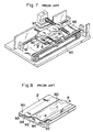
- a conventional optical card processing apparatus of this type includes a card holder 9 having a card holding section 90 on its top side, and a guide mechanism 91 on which the card holder 9 is reciprocatively mounted.
- the card holding section 90 is provided with strip-shaped card retaining plates 93 on both sides of the top of a card support plate 92, as shown in Fig. 8, and card insertion grooves 94 are formed between the card retaining plates 93 and the top side of the card support plate 92.
- a reversibly rotatable drive motor 96 is connected to the card holder 9 via a belt 95.
- an optical head 97 for recording information on and/or reproducing information from the optical card 8.
- the optical head 97 has an objective lens (not shown) whose focusing is controlled in such a manner that an irradiating beam produced at recording/reproduction has its focal point formed on the surface of the information recording medium of the optical card 8 at all times.
- Fig. 9 illustrates the entirety of the optical card 8 as well as a portion of the card shown in enlarged form.
- the optical card 8 undergoes a data reading (reproduction) or data writing (recording) operation performed by an optical processing apparatus.
- the optical card is not limited to that of the type which undergoes recording/reproduction optically but also covers optical cards of the type subjected to recording/reproduction electromagnetically.
- An information recording zone 80 of the optical card 8 is provided with a number of information recording tracks 81 defined by track guides 82. Bits representing information are recorded on these tracks 81 in the form of pits (in the case of a card for capable of undergoing recording/reproduction optically).
- the track guides 82 are for the purpose of causing the recording/reproduction optical head to follow the tracks on the card (tracking control).
- the card holder 9 Since the card holder 9 is so arranged that the two longitudinal side edges of the four edges of the optical card 8 are held by the retaining plates 93, the front and rear edges of the optical card 8 are the free edges when the card is being held by the card holder 9. Consequently, the optical card sustains warping or curvature in such a manner that its four sides rise, as shown in Fig. 10a, or in such a manner that its front and rear side edges bow upwardly, as depicted in Fig. 10b. When this occurs, the curvature cannot be corrected by the card holding section 90 and a large focal-point error is produced by such buckling at the time of recording/reproduction. The result is a decline in recording/reproduction performance.
- Fig. 8 illustrates the warped optical card 8 in a state held by the card holder 9.
- the state of the information recording zone 80 of the optical card 8 which appears between the retaining plates 93 is such that portions A, B near the front and rear edges of the card rise while the central portion C is recessed.
- Fig. 11 illustrates conditions under which focal-point error is produced when reproducing recorded information from the optical card 8 warped as shown in Fig. 8. It will be appreciated that focal-point error fluctuates in dependence upon the deformation at the front and rear edge portions A, B and the central portion C.
- an object of the present invention is to provide an optical card processing apparatus wherein the manner in which an optical card is held by a card holder is specially contrived to correct optical card deformation and suppress the occurrence of vibration, whereby focal-point error attributed to curvature and vibration of the card is reduced and feed velocity raised to realize high-speed recording/reproduction.
- the foregoing object is attained by providing an optical card processing apparatus for performing at least one of recording information on and reproducing information from a rectangular optical card by reciprocating a card holder, which holds the optical card, relative to an optical head, characterized in that the card holder is provided with holding means for holding, in a pressed state, at least three sides of the optical card.
- the optical card When the optical card is set in the card holder, at least three sides of the card are held in a pressed state. Therefore, even if the card is deformed such as by undergoing warping or curvature, the deformation is sufficiently corrected. Moreover, in comparison with the conventional arrangement in which two sides of the card are held, there are fewer free ends of the card that are capable of vibrating.
- curvature of the optical card and card vibration ascribable to its free ends are reduced, thereby diminishing focal-point error at recording/reproduction to improve recording/reproduction performance.
- the feed velocity of the card holder can be raised to make possible high-speed recording/reproduction.
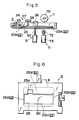
- Figs. 1 through 3 illustrate the internal mechanism of an optical card processing apparatus according to an embodiment of the present invention.
- the optical card processing apparatus includes a case 10 having a card insertion slot 1, a pair of guide rods 11 arranged in parallel within the case 10 for reciprocatively supporting a card holder 2, an optical head 5 disposed below the holder traveling path on the side near the card inlet slot 1, and a holder feed mechanism 4 similarly disposed below the holder traveling path rearwardly of the optical head 5.
- the guide rods 11 in the card holder 2 freely slidably support bearings 21 provided on both sides of the card holder 2, and the latter is further provided with a card holding mechanism 20 for holding, in a pressed state, the four sides of the rectangular card 8, namely the two longitudinal sides and the front and rear sides of the card.
- the card holding mechanism 20 comprises a card support plate 22 constituting the bottom face of the card holder 2, a retaining plate 23 for pressing the optical card 8 against the card support plate 22, a pressuring mechanism 24 for causing the retaining plate 23 to apply pressure to the card support plate 22, and a release mechanism 3 for urging the retaining plate 23 upward to release the optical card 8 from the held state.
- the card support plate 22 is formed as a unitary body having a front wall 2a, rear wall 2b and longitudinal side walls 2c, 2d constituting the card holder 2, and the plate floor is formed to have a rectangular window 25 in which the information recording zone 80 of the optical card 8 is situated. Accordingly, when the optical card 8 is set on the card support plate 22 with its information recording zone 80 facing downward, the two longitudinal sides of the optical card 8 are supported by two longitudinal side portions 22c, 22d of the card support plate 22, and the front and rear sides of the card are supported by front and rear end portions 22a, 22b of the card support plate 22.
- the retaining plate 23 has a size corresponding to that of the optical card 8. One end of the retaining plate 23 is pivotally supported on the rear end portion 22b of the card support plate 22, and the other end of the retaining plate 23 is free to swing up and down. An arm member 26 projecting from one side of the retaining plate 23 to outside is attached to the retaining plate 23.
- the pressuring mechanism 24 includes a mounting wall 27 spanning the two side walls 2c, 2d of the card holder 2, and two coil springs 28 disposed between the mounting wall 27 and the upper surface of the retaining plate 23 on both its longitudinal side portions.
- the release mechanism 3 includes such components as a cam mechanism and solenoid, and is disposed on a side portion rearwardly of a card loading/ejecting mechanism 7, described later.
- the release mechanism 3 is equipped with a vertically operated actuating member 30. By elevating the actuating member 30, the arm member 26 of the retaining plate 23 is urged upwardly to tilt up the retaining plate 23. By lowering the actuating member 30, the upward urging force is eliminated and the retaining plate 23 is returned to the horizontal state.
- the rear wall 2b of the card holder 2 is provided with a guide shaft 12 at right angles to the direction of holder movement.
- a slide member 13 is freely slidably disposed on the guide shaft 12 and is linked to the holder feed mechanism 4.
- the holder feed mechanism 4 includes two vertical rotary shafts 40a, 40b freely rotatably provided on a fixed frame provided inside the case 10, pulleys 41a, 41b fixed to upper ends of the respective rotary shafts 40a, 40b, an endless belt 42 wound about the pulleys 41a, 41b, and a connecting pin 43 provided on the endless belt 42 at an appropriate location and freely rotatably connected to the slide member 13.
- a pulley 45 is supported on the lower end of the rotary shaft 40b and is coupled via transmission means 44 such as a belt to an output shaft of a drive motor 46 which rotates in one direction. Attached to the lower end of the other rotary shaft 40a is an encoder 47 for detecting the amount of feed of the card holder 2.
- the optical head 5 is supported on a lead screw 50 and a guide shaft 51 that are disposed orthogonal to the direction of travel of the card holder 2.
- the lead screw 50 is driven by a reversibly rotatable head feed motor 52.
- the optical head 5 is shifted by the guide shaft 51 and lead screw 50 in the direction perpendicular to the feed direction of the optical head 8, thereby accessing the information recording tracks 81.
- a sensor 6 for sensing an introduced optical card 8 and the card loading/ejecting mechanism 7 actuated in response to a detection output from the sensor 6 to automatically transport the optical card 8 into and out of the card holding mechanism 20 of the card holder 2.
- the card loading/ejecting mechanism 7 comprises a driving roller 70 disposed at a position above the holder travel path in the vicinity of the card insertion slot 1, and a loading auxiliary mechanism 71 disposed below the holder travel path at a position opposing the driving roller 70.
- the loading auxiliary mechanism 71 comprises a driven roller 72 and a solenoid 73 for raising and lowering the driven roller 72 and is so situated that when the driven roller 72 is raised it will pass through the rectangular window 25 in the card holder 2 and contact the driving roller 70.
- the driving roller 70 is driven reversibly by a loading motor 74 so that the optical card 8 placed in the card insertion slot 1 is clamped between the roller 70 and the driven roller 72 to be introduced to the card holder 2 and then fed out to the card insertion slot 1 following processing.
- numeral 29 denotes a hole formed in the retaining plate 23 in order that the driving roller 70 may project below the retaining plate 23.
- Numeral 25a in Fig. 6 denotes a cut-out, which communicates with the rectangular window 25, for allowing the driven roller 72 to project above the card support plate 22.
- the card holder 2 In a standby state prior to insertion of the optical card 8, the card holder 2 is situated in the vicinity of the card insertion slot 1 and the retaining plate 23 of the card holder 2 is in a state in which it is urged upwardly by the actuating member 30 of the release mechanism 3. Consequently, the card support plate 22 of the card holder 2 and the retaining plate 23 are spaced apart from each other, as a result of which the optical card 8 is capable of being received on the card support plate 22.
- the loading motor 74 of the card loading/ejecting mechanism 7 begins operating and the driving roller 70 is rotated.
- the driven roller 72 of the loading auxiliary mechanism 71 is elevated to a position opposing the driving roller 70, so that the inserted optical card 8 is clamped between the driving roller 70 and driven roller 72 and introduced to the card holder 2.
- the driven roller 72 of the loading auxiliary mechanism 71 is lowered, as shown in Fig.
- Fig. 6 illustrates the optical card 8 in a state held on the card support plate 22 by the retaining plate 23.
- the information recording zone 80 of the optical card 8 is situated opposite the position of the rectangular window 25, and the four sides of the optical card 8 are held clamped between the card support plate 22 and the retaining plate 23 while in intimate contact with the front end portion 22a, rear end portion 22b and both longitudinal side portions 22c, 22d of the card support plate 22. Accordingly, even if the optical card 8 undergoes curvature, such deformation is corrected by pressure applied by the coil spring 28. Since all four sides of the optical card 8 are held, there are no free ends to vibrate.
- the holder feed mechanism 4 begins operating in conjunction with the card holder and the endless belt 42 is caused to travel by drive supplied by the motor 46.
- the connecting pin 43 on the endless belt 42 pulls the card holder 2 along the guide shafts 11 via the slide member 13 to shift the card holder 2 in a first direction (from the side of the insertion slot 1 toward the interior of the case 10).
- the connecting pin 43 When the connecting pin 43 reaches the outer periphery of the pulley 41b, the pin slides the slide member 13 in the width direction of the card holder 2 and the pulley 41b makes a half revolution to shift the slide member in a second direction opposite the first direction mentioned above (namely toward the insertion slot 1). Thereafter, through an operation similar to that involving the first direction, the connecting pin 43 shifts the guide holder 2 in the second direction along the guide shafts 11 via the slide member 13. Thus, the card holder 2 is reciprocated by continuous rotation of the drive motor 46 in one direction.
- the optical head 5 moves relative to the information recording track 81 of the optical card 8 to record and/or reproduce information.
- the head feed motor 52 is actuated and the optical head 5 accesses the tracks on the optical card 8 while traveling along the guide shaft 51 and lead screw 50, after which the same card feeding operation is repeated.
- the optical card 8 is introduced and extracted by the loading/ejecting mechanism 7 while inclined with respect to the card holder 2.
- the information recording zone 80 of the optical card 8 does not contact the front edge portion 22a and rear edge portion 22b (and of course, the two side portions 22c, 22d) of the card support plate 22. Accordingly, damage to the information recording zone 80 of the optical card 8 owing to contact between the zone and any mechanical member can be prevented before it occurs.
Claims (6)
- Appareil de traitement de carte optique comprenant :
un mécanisme d'alimentation de support (4) pour déplacer selon un mouvement de va et vient un support de carte (2) qui supporte une carte optique (8) ;
une tête optique (5) pour soumettre la carte optique supportée par ledit support de carte à au moins une opération prise parmi une opération d'enregistrement d'information et une opération de reproduction d'information : et
un mécanisme de support de carte (20) prévu sur ledit support de carte, caractérisé en ce que ledit mécanisme de support de carte supporte par pression au moins trois côtés de la carte optique. - Appareil selon la revendication 1, dans lequel ledit mécanisme de support de carte (20) comprend :
une plaque de support de carte (22) comportant une fenêtre (25) on une position correspondant à une zone d'enregistrement d'information (80) de la carte optique ;
une plaque de retenue (23) pour presser la carte optique contre ladite plaque de support (22) ; et
un mécanisme de pression (24) pour presser ladite plaque de retenue (23) suivant la direction de ladite plaque de support de carte (22). - Appareil selon la revendication 2, comprenant en outre un mécanisme de libération (3) pour déplacer ladite plaque de retenue de manière à l'éloigner de ladite plaque de support de carte en s'opposant à une force de pression provenant dudit mécanisme de pression (24) lorsque ledit support de carte est sur un côté de fente d'insertion de carte.
- Appareil selon la revendication 3, comprenant en outre un mécanisme de chargement de carte optique (7) pour alimenter une carte optique insérée dans un espace ménagé entre ladite plaque de retenue et ladite plaque de support de carte, lesquelles plaque de retenue et plaque de support de carte sont espacées l'une de l'autre, lorsque ledit support de carte est sur le côté d'entrée d'insertion de carte.
- Appareil selon la revendication 3, comprenant on outre un mécanisme de chargement/éjection de carte optique (7) pour alimenter une carte optique insérée dons un espace ménagé entre ladite plaque de retenue et ladite plaque de support de carte et pour éjecter la carte optique chargée hors de cet espace, lesquelles plaque de retenue et plaque de support de carte sont espaces l'une de l'autre, lorsque ledit support de carte est sur le côté d'entrée d'insertion de carte, l'alimentation et l'éjection de la carte optique étant réalisées à l'oblique par rapport audit support de carte.
- Appareil selon la revendication 1, comprenant en outre un mécanisme de chargement/éjection de carte optique (7) pour alimenter la carte optique dans ledit support de carte et pour l'éjecter hors de celui-ci suivant un plan différent d'un plan selon lequel au moins trois côtés de la carte optique sont maintenus dans ledit mécanisme de support de carte (20).
Applications Claiming Priority (2)
| Application Number | Priority Date | Filing Date | Title |
|---|---|---|---|
| JP1054640A JPH031361A (ja) | 1989-03-07 | 1989-03-07 | 光カード処理装置 |
| JP54640/89 | 1989-03-07 |
Publications (2)
| Publication Number | Publication Date |
|---|---|
| EP0386705A1 EP0386705A1 (fr) | 1990-09-12 |
| EP0386705B1 true EP0386705B1 (fr) | 1994-07-20 |
Family
ID=12976375
Family Applications (1)
| Application Number | Title | Priority Date | Filing Date |
|---|---|---|---|
| EP90104277A Expired - Lifetime EP0386705B1 (fr) | 1989-03-07 | 1990-03-06 | Procédé de traitement de carte optique |
Country Status (5)
| Country | Link |
|---|---|
| US (1) | US5099111A (fr) |
| EP (1) | EP0386705B1 (fr) |
| JP (1) | JPH031361A (fr) |
| AT (1) | ATE108938T1 (fr) |
| DE (1) | DE69010719T2 (fr) |
Families Citing this family (20)
| Publication number | Priority date | Publication date | Assignee | Title |
|---|---|---|---|---|
| US6938825B1 (en) | 1989-04-24 | 2005-09-06 | Ultracard, Inc. | Data system |
| US6131816A (en) * | 1989-04-24 | 2000-10-17 | Ultracard, Inc. | Data system with support surfaces for reciprocating data head |
| JP2753595B2 (ja) * | 1990-09-28 | 1998-05-20 | キヤノン株式会社 | 情報記録媒体搬送装置 |
| JPH04195277A (ja) * | 1990-10-01 | 1992-07-15 | Olympus Optical Co Ltd | カード載置装置 |
| US5317138A (en) * | 1991-02-20 | 1994-05-31 | Olympus Optical Co., Ltd. | Information recording and or reproducing apparatus for use in hybrid type information recording medium |
| DE69226035D1 (de) * | 1991-04-10 | 1998-08-06 | Canon Kk | Gerät für Informationsaufzeichnungsträger |
| JP3311362B2 (ja) * | 1991-04-10 | 2002-08-05 | 株式会社日本コンラックス | 情報記録再生装置 |
| US5428210A (en) * | 1992-01-10 | 1995-06-27 | National Bancard Corporation | Data card terminal with embossed character reader and signature capture |
| US5397886A (en) * | 1993-06-10 | 1995-03-14 | Mos Magnetics Corporation | Magnetic stripe and/or micro chip card motorized reader/encoder mechanism |
| JPH09245129A (ja) * | 1996-03-06 | 1997-09-19 | Nippon Conlux Co Ltd | カード搬送制御方法および装置 |
| FR2755270B1 (fr) * | 1996-10-25 | 1999-03-05 | Sinet Maurice | Dispositif de lecture/ecriture de carte du type magnetique ou a puce |
| US5898159A (en) * | 1997-05-28 | 1999-04-27 | Huang; Kong-Hung | Structural improvement on ID card processor |
| WO2000000003A1 (fr) * | 1998-06-26 | 2000-01-06 | Card Tech, Inc. | Systeme de donnees presentant des surfaces d'appui d'une tete de lecture/ecriture de donnees a mouvement alternatif |
| US6871787B1 (en) | 1998-07-10 | 2005-03-29 | Ultracard, Inc. | Data storage card having a glass substrate and data surface region and method for using same |
| US7487908B1 (en) * | 1999-10-23 | 2009-02-10 | Ultracard, Inc. | Article having an embedded accessible storage member, apparatus and method for using same |
| US8397998B1 (en) | 1999-10-23 | 2013-03-19 | Ultracard, Inc. | Data storage device, apparatus and method for using same |
| US7036739B1 (en) * | 1999-10-23 | 2006-05-02 | Ultracard, Inc. | Data storage device apparatus and method for using same |
| TW526988U (en) * | 2000-01-29 | 2003-04-01 | Shen Yu Nung | Data storage medium and data reading device reading the same |
| US6969006B1 (en) | 2000-09-15 | 2005-11-29 | Ultracard, Inc. | Rotable portable card having a data storage device, apparatus and method for using same |
| JP5117543B2 (ja) * | 2010-06-30 | 2013-01-16 | 日本電産コパル株式会社 | 紙葉類用レーザマーカ |
Family Cites Families (5)
| Publication number | Priority date | Publication date | Assignee | Title |
|---|---|---|---|---|
| DE2837537C2 (de) * | 1978-08-28 | 1983-04-28 | Gestra-KSB Vertriebsgesellschaft mbH & Co KG, 2800 Bremen | Mehrstufiges, thermostatisches Ventil |
| DE3445185A1 (de) * | 1984-12-11 | 1986-06-12 | Nixdorf Computer Ag, 4790 Paderborn | Aufnahmeeinheit fuer eine einen elektronischen schaltkreis enthaltende datenkarte |
| BE904746A (fr) * | 1986-05-12 | 1986-09-01 | Staar Dev Co Sa | Systeme d'entrainement. |
| JP2754530B2 (ja) * | 1986-07-25 | 1998-05-20 | オムロン株式会社 | カード処理装置 |
| EP0296590B1 (fr) * | 1987-06-23 | 1993-10-27 | Omron Tateisi Electronics Co. | Appareil de traitement de carte optique |
-
1989
- 1989-03-07 JP JP1054640A patent/JPH031361A/ja active Pending
-
1990
- 1990-03-02 US US07/487,392 patent/US5099111A/en not_active Expired - Lifetime
- 1990-03-06 AT AT90104277T patent/ATE108938T1/de not_active IP Right Cessation
- 1990-03-06 DE DE69010719T patent/DE69010719T2/de not_active Expired - Fee Related
- 1990-03-06 EP EP90104277A patent/EP0386705B1/fr not_active Expired - Lifetime
Also Published As
| Publication number | Publication date |
|---|---|
| US5099111A (en) | 1992-03-24 |
| EP0386705A1 (fr) | 1990-09-12 |
| ATE108938T1 (de) | 1994-08-15 |
| DE69010719T2 (de) | 1995-03-16 |
| JPH031361A (ja) | 1991-01-08 |
| DE69010719D1 (de) | 1994-08-25 |
Similar Documents
| Publication | Publication Date | Title |
|---|---|---|
| EP0386705B1 (fr) | Procédé de traitement de carte optique | |
| US4994658A (en) | Apparatus for controlling movement of an optical memory card for data transfer therewith | |
| JPH0636266B2 (ja) | 情報記録再生装置 | |
| JP2753595B2 (ja) | 情報記録媒体搬送装置 | |
| EP0296590A2 (fr) | Appareil de traitement de carte optique | |
| US5189661A (en) | Card carrier | |
| US5650990A (en) | Disc tray in a mini-disc player with an elastically mounted guide roller | |
| JPH0950492A (ja) | 情報処理装置 | |
| JPH04311870A (ja) | 情報記録再生装置 | |
| JP2797481B2 (ja) | 光カード処理装置 | |
| US6097692A (en) | Apparatus for feeding and ejecting an optical card | |
| JPH0567250A (ja) | 複合型カードの記録再生装置 | |
| JPH0542068B2 (fr) | ||
| US5264687A (en) | Optical card processing apparatus | |
| EP0794504B1 (fr) | Méthode et appareil de contrôle de transport de carte | |
| JPH03292172A (ja) | 通帳リーダー | |
| JP2908901B2 (ja) | 情報記録媒体搬送装置 | |
| JPH04344368A (ja) | 光カード駆動装置 | |
| JP2908900B2 (ja) | 情報記録媒体搬送装置 | |
| JP3350103B2 (ja) | 光ディスク装置 | |
| JPH0535928A (ja) | カード状記録媒体の記録再生装置 | |
| JPH0573728A (ja) | 情報記録媒体搬送装置 | |
| JPH0581755A (ja) | 光カード搬送装置 | |
| JPH0527855U (ja) | 光学式情報記録再生装置 | |
| JP2000030327A (ja) | 情報記録再生装置 |
Legal Events
| Date | Code | Title | Description |
|---|---|---|---|
| PUAI | Public reference made under article 153(3) epc to a published international application that has entered the european phase |
Free format text: ORIGINAL CODE: 0009012 |
|
| 17P | Request for examination filed |
Effective date: 19900306 |
|
| AK | Designated contracting states |
Kind code of ref document: A1 Designated state(s): AT BE CH DE DK ES FR GB GR IT LI NL SE |
|
| 17Q | First examination report despatched |
Effective date: 19930903 |
|
| GRAA | (expected) grant |
Free format text: ORIGINAL CODE: 0009210 |
|
| AK | Designated contracting states |
Kind code of ref document: B1 Designated state(s): AT BE CH DE DK ES FR GB GR IT LI NL SE |
|
| PG25 | Lapsed in a contracting state [announced via postgrant information from national office to epo] |
Ref country code: AT Effective date: 19940720 Ref country code: DK Effective date: 19940720 Ref country code: NL Effective date: 19940720 Ref country code: LI Effective date: 19940720 Ref country code: GR Free format text: LAPSE BECAUSE OF FAILURE TO SUBMIT A TRANSLATION OF THE DESCRIPTION OR TO PAY THE FEE WITHIN THE PRESCRIBED TIME-LIMIT Effective date: 19940720 Ref country code: BE Effective date: 19940720 Ref country code: CH Effective date: 19940720 Ref country code: ES Free format text: THE PATENT HAS BEEN ANNULLED BY A DECISION OF A NATIONAL AUTHORITY Effective date: 19940720 |
|
| REF | Corresponds to: |
Ref document number: 108938 Country of ref document: AT Date of ref document: 19940815 Kind code of ref document: T |
|
| ITF | It: translation for a ep patent filed |
Owner name: STUDIO TORTA SOCIETA' SEMPLICE |
|
| REF | Corresponds to: |
Ref document number: 69010719 Country of ref document: DE Date of ref document: 19940825 |
|
| ET | Fr: translation filed | ||
| PG25 | Lapsed in a contracting state [announced via postgrant information from national office to epo] |
Ref country code: SE Effective date: 19941020 |
|
| REG | Reference to a national code |
Ref country code: CH Ref legal event code: PL |
|
| NLV1 | Nl: lapsed or annulled due to failure to fulfill the requirements of art. 29p and 29m of the patents act | ||
| PLBE | No opposition filed within time limit |
Free format text: ORIGINAL CODE: 0009261 |
|
| STAA | Information on the status of an ep patent application or granted ep patent |
Free format text: STATUS: NO OPPOSITION FILED WITHIN TIME LIMIT |
|
| 26N | No opposition filed | ||
| REG | Reference to a national code |
Ref country code: GB Ref legal event code: IF02 |
|
| PGFP | Annual fee paid to national office [announced via postgrant information from national office to epo] |
Ref country code: FR Payment date: 20040315 Year of fee payment: 15 |
|
| PG25 | Lapsed in a contracting state [announced via postgrant information from national office to epo] |
Ref country code: IT Free format text: LAPSE BECAUSE OF NON-PAYMENT OF DUE FEES Effective date: 20050306 |
|
| PG25 | Lapsed in a contracting state [announced via postgrant information from national office to epo] |
Ref country code: FR Free format text: LAPSE BECAUSE OF NON-PAYMENT OF DUE FEES Effective date: 20051130 |
|
| REG | Reference to a national code |
Ref country code: FR Ref legal event code: ST Effective date: 20051130 |
|
| PGFP | Annual fee paid to national office [announced via postgrant information from national office to epo] |
Ref country code: GB Payment date: 20060310 Year of fee payment: 17 |
|
| PGFP | Annual fee paid to national office [announced via postgrant information from national office to epo] |
Ref country code: DE Payment date: 20060331 Year of fee payment: 17 |
|
| GBPC | Gb: european patent ceased through non-payment of renewal fee |
Effective date: 20070306 |
|
| PG25 | Lapsed in a contracting state [announced via postgrant information from national office to epo] |
Ref country code: DE Free format text: LAPSE BECAUSE OF NON-PAYMENT OF DUE FEES Effective date: 20071002 |
|
| PG25 | Lapsed in a contracting state [announced via postgrant information from national office to epo] |
Ref country code: GB Free format text: LAPSE BECAUSE OF NON-PAYMENT OF DUE FEES Effective date: 20070306 |