EP0386524A1 - Device for packaging objects of different size - Google Patents
Device for packaging objects of different size Download PDFInfo
- Publication number
- EP0386524A1 EP0386524A1 EP90103316A EP90103316A EP0386524A1 EP 0386524 A1 EP0386524 A1 EP 0386524A1 EP 90103316 A EP90103316 A EP 90103316A EP 90103316 A EP90103316 A EP 90103316A EP 0386524 A1 EP0386524 A1 EP 0386524A1
- Authority
- EP
- European Patent Office
- Prior art keywords
- packaging
- members
- group
- folding
- packs
- Prior art date
- Legal status (The legal status is an assumption and is not a legal conclusion. Google has not performed a legal analysis and makes no representation as to the accuracy of the status listed.)
- Granted
Links
Images


Classifications
-
- B—PERFORMING OPERATIONS; TRANSPORTING
- B65—CONVEYING; PACKING; STORING; HANDLING THIN OR FILAMENTARY MATERIAL
- B65B—MACHINES, APPARATUS OR DEVICES FOR, OR METHODS OF, PACKAGING ARTICLES OR MATERIALS; UNPACKING
- B65B11/00—Wrapping, e.g. partially or wholly enclosing, articles or quantities of material, in strips, sheets or blanks, of flexible material
- B65B11/06—Wrapping articles, or quantities of material, by conveying wrapper and contents in common defined paths
- B65B11/08—Wrapping articles, or quantities of material, by conveying wrapper and contents in common defined paths in a single straight path
- B65B11/10—Wrapping articles, or quantities of material, by conveying wrapper and contents in common defined paths in a single straight path to fold the wrappers in tubular form about contents
- B65B11/12—Wrapping articles, or quantities of material, by conveying wrapper and contents in common defined paths in a single straight path to fold the wrappers in tubular form about contents and then to form closing folds of similar form at opposite ends of the tube
-
- B—PERFORMING OPERATIONS; TRANSPORTING
- B65—CONVEYING; PACKING; STORING; HANDLING THIN OR FILAMENTARY MATERIAL
- B65B—MACHINES, APPARATUS OR DEVICES FOR, OR METHODS OF, PACKAGING ARTICLES OR MATERIALS; UNPACKING
- B65B59/00—Arrangements to enable machines to handle articles of different sizes, to produce packages of different sizes, to vary the contents of packages, to handle different types of packaging material, or to give access for cleaning or maintenance purposes
- B65B59/003—Arrangements to enable adjustments related to the packaging material
-
- B—PERFORMING OPERATIONS; TRANSPORTING
- B65—CONVEYING; PACKING; STORING; HANDLING THIN OR FILAMENTARY MATERIAL
- B65B—MACHINES, APPARATUS OR DEVICES FOR, OR METHODS OF, PACKAGING ARTICLES OR MATERIALS; UNPACKING
- B65B2210/00—Specific aspects of the packaging machine
- B65B2210/02—Plurality of alternative input or output lines or plurality of alternative packaging units on the same packaging line for improving machine flexibility
Definitions
- the invention relates to a device (packaging machine) for packaging objects of different sizes in a blank of packaging material (large pack), in particular for packing a group of small packs (paper handkerchief packs) in an outer blank made of plastic film or the like (container), in a packaging station with packaging elements, such as conveying elements for feeding and providing a blank, slide for transporting the small packs, folding elements and, if necessary, sealing elements for sealing folding tabs.
- packaging elements such as conveying elements for feeding and providing a blank, slide for transporting the small packs, folding elements and, if necessary, sealing elements for sealing folding tabs.
- Paper handkerchief packs are usually offered as large packs (bundles), with several of these small packs being combined to form the bundle by an outer wrapping. This can consist of six, eight, ten, twelve, eighteen or more small packs (paper handkerchief packs).
- a "packaging line” consists of a folding machine (for the manufacture and stacking of the paper handkerchiefs), a packaging machine for the manufacture of the paper handkerchief packs, a pack packer, a cartoning machine and so on.
- the invention is based on the object of designing a device for producing packs of different sizes (packs) in such a way that a simple, rapid conversion to or adaptation to the processing of objects or packs of different sizes can take place.
- the device according to the invention is characterized in that at least individual packaging members which are set up for the format of the pack to be produced (large pack / bundle) can be exchanged for those for the production of packs (large packs / bundle) of other dimensions are ordered.
- the format-dependent organs of the packaging machine are available in several versions (sets).
- the relevant packaging elements are installed by changing them.
- the packaging elements that need to be replaced are arranged on brackets or supporting elements, which enable a quick and easy replacement.
- the packaging machine is assigned at least two preferably complete sets of packaging elements for different dimensions of the packs (bundles) to be produced, the sets alternatively being movable into a packaging position.
- the relevant packaging organs are in the position applicable to the packaging process.
- movable packaging elements are geared to stationary drives of the packaging machine.
- the packaging station of the device can also be designed such that two or more (complete) sets of packaging elements for different packs are installed in a fixed position and that the objects to be packaged (groups of small packs) that are supplied can alternatively be fed to one or the other group of packaging elements.
- sets of packaging elements which are to be exchanged for one another
- these can be arranged on supports or holders which are displaceably mounted on rails, supporting rods or the like, the set of packaging elements in the working position being subtracted from the rails, rods or the like and that for the new format of the packs directed set of packaging elements is pushed onto the rods, rails or the like.
- Another proposal of the invention is that holders and carriers for at least two (complete) sets of packaging elements are arranged in the packaging station, one set of packaging elements being moved into the packaging position while another set of packaging elements is in a waiting position or in an exchange position.
- An embodiment in which two effective complete sets of packaging members are assigned to a packaging machine is particularly advantageous. These are arranged approximately centrally offset to the longitudinal axis of a feeder for the small packs and can be rotated about a central pivot bearing with an upright axis of rotation, such that one set of the packaging members in the packaging position and another set 180 ° offset in an exchange position. In the packaging position, movable packaging elements are automatically coupled to stationary drives.
- the packaging elements also include folding elements for folding tabs in the outer wrapping of the container. On the one hand, it is about a longitudinal fold that is specially designed. To produce the same, the set of packaging elements is equipped with an upper folder and a lower folder.
- Side folds are also to be produced. These consist of front and rear, upright side lobes as well as upper and lower lobes.
- the former are brought into the folding position by means of reciprocally movable side folders, the side folders being effective in a special, novel way.
- Upper flaps and lower flaps are moved into the folding position in a manner known per se via stationary folding switches, wherein these are specially designed to apply sealing heat and pressure to the side fold.
- the exemplary embodiments shown in the drawings deal with the production of large packages, so-called containers 20, from a plurality of small packages 21, in the present case paper tissue packs.
- the packs 20 are produced by a packaging machine set up for this purpose, a pack packer 22).
- This is part of a manufacturing and packaging system for paper handkerchiefs, a "line”. It consists of a folding machine 23, a handkerchief packaging machine 24, one of these downstream tape units 25 for attaching a sealing strip to the small package 21, a stacking head 26, the subsequent packer 22 and a carton packer 27 connected to it.
- the small packs 21 are produced in two lines in the present exemplary embodiment.
- a common row of packs 28 is formed from possibly several small packs 21 arranged one above the other. This is fed to the packer 22 by a feed conveyor 29.
- the large packs can have different dimensions, depending on the number of small packs 21 per pack 20.
- Small packs 20 consist of six small packs 21, large packs 20 contain, for example, twenty-four small packs. These are formed into a regular group 30 of small packs 21 aligned side by side and one above the other.
- the container 20 is formed by a covering 31 made of plastic film.
- the pack packer 22 is designed in such a way that packs 20 of different sizes can be moved by replacing packaging elements.
- Packaging organs are folding organs for the wrapping 31, sliders for the transport of the groups 30, conveying organs for film webs and sealing organs.
- the number and type of packaging elements result from the design of the container 20 or the steps for the production of the wrapper 31.
- the wrapping 31 is folded in a special way and leads to a container 20 which is special with respect to the wrapping 31.
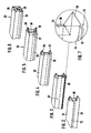
- the folding sequence is shown in FIGS. 2 to 6.
- a blank for the wrapper 31 is held ready in the vertical plane and folded in a U shape around the contents (group 30) by conveying the group 30 through the plane of the blank.
- horizontally directed longitudinal tabs 32, 33 which initially protrude at the rear of group 30 have different lengths.
- the upper longitudinal tab 32 is dimensioned such that the rearward-facing long side of the container 20 or the group 30 is covered at full height.
- This longitudinal tab 32 is folded against the back of the group 30 in the upright position (Fig. 3).
- a lower edge tab 34 of the longitudinal tab 32 is in this folding process on the top of the corresponding dimensioned lower longitudinal tab 33 and sealed with this by heat and pressure (Fig. 3 and detail in Fig. 7).
- a double-layered edge strip 35 formed in this way is then folded into an upright position until it rests on the side surface or on the upper longitudinal tab 32 (folded position according to FIG. 4).
- Front side flaps 36 and rear side flaps 37 are successively folded against the side surface of group 30.
- the front side flap 36 is folded during the transport of the group 30 with the wrapping 31 (FIG. 2).
- upper lobes 38 and lower lobes 39 are folded over to rest against the side surfaces or on the side lobes 36, 37 (FIG. 6).
- Upper flap 38 and lower flap 39 on the one hand and side flaps 36 and 37 on the other hand are sealed together by heat and pressure.
- the means required for this folding and sealing process together form a complete set of packaging elements.
- the bundle packer 22 is assigned a plurality of sets of packaging members, these being expediently completely interchangeable to adapt to different formats of the bundles 20.
- the pack packer 22 shown and described here is set up to accommodate two sets 40, 41 of the packaging members. These sets 40 and 41 are located in a packaging station 42. One of the sets, in the example shown in FIG. 1, the set 40 is in the packaging position 43. The small packs 21 or groups 30 are fed to this.
- the sets 40 and 41 are detachably connected to an adjustable carrying device, namely a rotating mechanism which alternatively moves the sets 40, 41 into the packaging position 43 or into an exchange position 44 by means of a rotary movement.
- an adjustable carrying device namely a rotating mechanism which alternatively moves the sets 40, 41 into the packaging position 43 or into an exchange position 44 by means of a rotary movement.
- the packaging elements of the set 41 are preferably completely replaced as a unit.
- the slewing gear here consists of an upright support column 45 which is firmly connected to a machine frame or a drive housing 46.
- a cross member 47 is rotatably mounted on the support column 45.
- holders for the sets 40, 41 are attached, namely transversely directed support rods 48.
- the packaging members of the sets 40, 41 are removable, namely removable, attached to these horizontally oriented support rods, which can be rotated around the support column with the cross-member 47.
- the pack row 28 is fed to the packing station 42 approximately in the middle.
- the feed conveyor 29 is centered on the support column 45.
- a number of small packs 21 corresponding to the size of the bundle - arranged in a plurality above one another - is detected by a transversely movable swivel slide 49 acting along a quarter circle and conveyed along a quarter circle on a plate-shaped top track 50 into the packaging position 43.
- the pivoting slide 49 is connected to a plate forming the upper track 50.
- the group 30 of the small packs 21 reaches the area of a lifting platform 51, the most important task of which is to lower the group from the level of the upper track 50 to the level of a main track 52.
- This consists of a height opposite the upper track 50 offset track plate 53.
- the packaging members are arranged or effective.
- the lifting platform 51 consists of a platform 54 on which the group 30 is pushed by the pivoting slide 49.
- the platform 54 is formed by three sub-platforms, which are supported on a lower, transverse support profile 55.
- the top of the lifting platform 51 is formed by a platform cover 56, which lies on top of the group 30.
- the platform cover 56 is connected to an upper cross bar 57.
- These and the lower support profile 55 are connected to one another by upright guide rods 58.
- the guide rods 58 can be moved up and down in fixed slide bearings 59 on the track plate 53.
- the lifting platform 51 Another special feature of the lifting platform 51 is that its side walls 60 can be moved transversely in order to exert a lateral pressure on the small packs 21 of the group 30.
- the side walls 60 are pivotably mounted on pivot arms 61 which are connected to the lower support profile 55 via a pivot bearing 62. When a group 30 is received, the side walls 60 are moved apart. The side walls 60 are then moved toward one another while compressing the small packs 21.
- the lifting platform 51 In the upper starting position (FIG. 12), the lifting platform 51 is aligned with the platform 54 on the upper track 50. After group 30 has been taken up, the lifting platform 51 is lowered until the platform 54 is aligned with the main track 52.
- the group 30 is ejected, namely by a pusher 63.
- This passes through the lifting platform 51, taking the group 30 with it.
- the pusher 63 is guided by pushrods 64, which are located below the track plate 53, while the pusher 63 itself moves above it.
- the group 30 passes through the level of a film web 65 when leaving the lifting platform 51. This is held ready in an upright plane by a film apparatus 66.
- the film web 65 is carried along by the group 30, a metered blank for forming the sheath 31 being separated from the film web 65 by separating knives 67.
- the blank wraps around the group 30 in a U-shape and is then folded in the manner described above (FIGS. 2-6).
- This folding takes place in the area of a folding station 68.
- side flaps 36 lying in the direction of movement are folded by side folders 69 on both sides of the movement path of group 30.
- the side butterflies are moved from a forward position of the group 30 to the area of the side flaps 36. These are folded by the side butterflies 69), the side butterflies 69 then being conveyed further with the group 30.
- the group 30 with the wrapping 31 (and with the side folders 69 in the folded position) is conveyed from a largely row of fully folded packs 20 until it abuts against a row of packs 70, while the row of packs 70 continues to move by one movement stroke corresponding to the size of a pack 20.
- the pusher 63 then returns to the starting position.
- the side folders 69 on both sides of the container 20 are moved in the opposite direction to the movement of the container 20, the side folder 69 emerging from the area of the group 30 on the not yet folded back of the wrapper 31 (position according to FIG. 2).
- the longitudinal flaps 32, 33 can be folded to form the edge strip 35 (folding processes according to FIGS. 3 and 4).
- An upper folder 71 is provided for the downward folding of the upper longitudinal tab 32, which here consists of a relatively thin wall with a lower angled leg 72. This presses the marginal tab 32 onto the lower, projecting longitudinal tab 33.
- the longitudinal tab 33 rests on a lower folder 73, which also serves as a sealing tool and is therefore heatable.
- the lower folder 73 is designed as an angular profile piece (FIG. 14).
- the approximately horizontally directed edge strip 35 rests on an upward leg 74 of the lower folder 73.
- the edge strip 35 is pressed by the upward movement of the lower folder 73 against the rear longitudinal surface of the envelope 31 or against the longitudinal tab 32 and is sealed with the latter.
- the upper folder 71 and lower folder 73 can only be moved up and down.
- the upper folder 71 is connected via holding rods 75 to a support profile 76 which extends transversely above the folding station 68. This is movably supported on the track plate 53 via lateral, upright guide rods 77.
- the guide rods 77 can be moved up and down in slide guides 78 in the web plate 53 in order to carry out the folding movement.
- the lower folder is mounted in the starting position below the web plate 53 or the main web 50, so that the leg 74 lies flush with the underside of the container 20.
- the lower folder 73 is laterally attached to a profile rod 79, which in turn is connected at the ends to guide rods 80. These in turn are mounted in an upright arrangement in sliding guides 81 on or in the track plate 53. Due to its function, the lower folder 73 carries out only slight lifting movements.
- the next group 30 is supplied with the wrapping 31, the side folders 69 running in the manner described with this subsequent group 30 with the side flaps 36 being folded over.
- the relative position of the side folders 69 is such that in the end position an in Enter the area of the side folder 69 in the direction of movement in the area of the side surfaces of the pack 20 in front of it in the pack row 70.
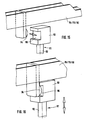
- the side flap 37 on the back in the conveying direction is folded over (FIG. 5).
- Upper flaps 38 and lower flaps 39 are folded during the further transport of the row of containers 70 by fixed, immovable folding members of a known type, namely by so-called folding switches (not shown). These are designed as fixed walls, which are arranged laterally next to the path of movement of the containers 20 and fold the upper tabs 38 and lower tabs 39 one after the other by the curved design of a folded edge during the movement of the containers 20.
- the side surface is sealed by a plate-shaped sealing tool 82, namely the overlapping regions of upper lobe 38 and lower lobe 39 with one another.
- the container 20 is then completed. It can now be more appropriate Are transported away in a manner via a fixed discharge conveyor 83.
- the side folders 69 are mounted in a similar manner to the upper folder 71 and the lower folder 73.
- a support profile 90 extends in the transverse direction below the web plate 53. Upright angle profiles are attached to the ends thereof, each of which accommodates the parallelepiped-shaped side folder 69. The support profile 90 is driven back and forth below the web plate 53 in the direction of movement of the container 20.
- the folding, conveying and sealing elements described above form a (complete) set 40, 41 of packaging elements.
- the sets 40, 41 can be modified with regard to the type and number of packaging elements.
- the packaging elements to be exchanged for changing the format of the packaging (bundle 20) to be produced are arranged on a common carrier, namely on the web plate 53.
- the plate-shaped top web 50 is also connected to the organs attached thereto, in particular the pivoting slide 49 .
- the common carrier (web plate 53) is easily removable and mounted on holding members in the packaging station 42. It is the horizontally directed support rods 48 which are connected to the crossbeam 47 and on which the track plate 53 is displaceable and can be removed with bearings 84 arranged on the underside thereof. To replace a complete set 40, 41, the track plate 53 is pulled down from the support rods 48 in the area of the exchange station 44 and exchanged for another set.
- the movable packaging members of a set 40, 41 are automatically coupled to fixed, non-exchangeable drives when a set 40, 41 is exchanged or moved into the packaging position 43.
- drive elements 85, 86, 87 for various movable packaging elements are arranged on the machine frame or on the drive housing 46 on the upper side.
- these drive members 85, 86, 87 consist of drive pieces 88 which are slidably displaceable on (two) fixed slide rods 89.
- the drive pieces 88 are driven by gears, for example cams, inside the drive housing 46.
- the drive elements shown here for example in FIG. 11 are assigned to the pusher 63 (drive element 85), the side folders 69 (drive element 86) and the sealing tools 82 (drive element 87).
- lifting members 91 are provided, which are also mounted on or on the drive housing 46 and can be moved up and down (FIGS. 15, 16). Such a lifting member 91 is assigned to the upper folder 71 and the lower folder 73.
- a lifting rod 92 is provided with a coupling head 93 at the upper end. This is automatically coupled by the movement of a set 40, 41 into and out of the packaging position 43 with the packaging member to be actuated.
- a rotatable coupling roller 94 is attached to the packaging member for this purpose.
- the transport of the bundles 20 or groups 30 after leaving the lifting platform 51 takes place under an upper guide in the form of a web cover 96. This extends from the range of movement of the lifting platform 51 to the completion of the bundles 20 with a distance corresponding to the exact dimensions of the bundles 20 of the web plate 53. Openings in the web cover 96 are provided for the passage of folding members etc.
- the film apparatus 66 with a separating knife 57 and conveyor rollers in the present exemplary embodiment is firmly connected to the support column 45 and therefore always remains in the packaging position 43.
- the film apparatus 66 can be arranged interchangeably or can be rotated with the movable sets 40, 41. This makes it possible to provide two different versions of the film apparatus. With the change of the set 40, 41, the film apparatus can also be changed.
Abstract
Description
Die Erfindung betrifft eine Vorrichtung (Verpackungsmaschine) zum Verpacken von Gegenständen unterschiedlicher Größe in jeweils einen Zuschnitt aus Verpackungsmaterial (Großpackung), insbesondere zum Verpacken einer Gruppe von Kleinpackungen (Papier-Taschentuch-Packungen) in einen Außenzuschnitt aus Kunststoffolie oder dergleichen (Gebinde), in einer Verpackungsstation mit Verpackungsorganen, wie Förderorgane für die Zuführung und Bereitstellung eines Zuschnitts, Schieber für den Transport der Kleinpackungen, Faltorgane und gegebenenfalls Siegelorgane für die Siegelung von Faltlappen.The invention relates to a device (packaging machine) for packaging objects of different sizes in a blank of packaging material (large pack), in particular for packing a group of small packs (paper handkerchief packs) in an outer blank made of plastic film or the like (container), in a packaging station with packaging elements, such as conveying elements for feeding and providing a blank, slide for transporting the small packs, folding elements and, if necessary, sealing elements for sealing folding tabs.
Die Aufgabe, Gegenstände unterschiedlicher Größe alternativ in ein und derselben Vorrichtung (Verpackungsmaschine) zu verpacken, tritt in der Verpackungstechnik vielfältig auf. Papier-Taschentuch-Packungen werden üblicherweise als Großpackungen (Gebinde) angeboten, wobei mehrere dieser Kleinpackungen durch eine äußere Umhüllung zu dem Gebinde vereinigt sind. Dieses kann aus sechs, acht, zehn, zwölf, achtzehn oder mehr Kleinpackungen (Papier-Taschentuch-Packungen) bestehen.The task of alternately packing objects of different sizes in one and the same device (packaging machine) occurs in a variety of ways in packaging technology. Paper handkerchief packs are usually offered as large packs (bundles), with several of these small packs being combined to form the bundle by an outer wrapping. This can consist of six, eight, ten, twelve, eighteen or more small packs (paper handkerchief packs).
Die Vorrichtung zum Herstellen dieser Großpackungen ist in einen Herstellungsfluß integriert. Üblicherweise besteht eine "Verpackungs-Linie" aus einer Falzmaschine (für die Herstellung und Stapelung der Papier-Taschentücher), einer Verpackungsmaschine für die Herstellung der Papier-Taschentuch-Packungen, einem Gebindepacker, einer Kartoniermaschine und so weiter.The device for producing these large packs is integrated into a production flow. Usually, a "packaging line" consists of a folding machine (for the manufacture and stacking of the paper handkerchiefs), a packaging machine for the manufacture of the paper handkerchief packs, a pack packer, a cartoning machine and so on.
Bei den bisher bekannten Verpackungsmaschinen für die Großpackungen (Gebinde) ist ein erheblicher Arbeitsaufwand erforderlich, wenn der Fertigungsprozeß auf ein anderes Format der Großpackung eingestellt werden soll. Die Umrüstung ist mit einem langwierigen Stillstand der Fertigungs-Linie verbunden.In the previously known packaging machines for the large packs (containers), a considerable amount of work is required if the manufacturing process is to be adjusted to a different format of the large pack. The changeover is associated with a lengthy downtime of the production line.
Der Erfindung liegt die Aufgabe zugrunde, eine Vorrichtung zum Herstellen von Packungen unterschiedlicher Größe (Gebinde) so auszubilden, daß eine einfache, schnelle Umstellung auf bzw. Anpassung an die Verarbeitung von Gegenständen bzw. Packungen anderer Größe erfolgen kann.The invention is based on the object of designing a device for producing packs of different sizes (packs) in such a way that a simple, rapid conversion to or adaptation to the processing of objects or packs of different sizes can take place.
Zur Lösung dieser Aufgabe ist die erfindungsgemäße Vorrichtung dadurch gekennzeichnet, daß wenigstens einzelne, auf das Format der herzustellenden Packung (Großpackung/Gebinde) eingerichtete Verpackungsorgane gegen solche für die Herstellung von Packungen (Großpackungen/Gebinde) anderer Abmessungen auswechselbar an geordnet sind.To achieve this object, the device according to the invention is characterized in that at least individual packaging members which are set up for the format of the pack to be produced (large pack / bundle) can be exchanged for those for the production of packs (large packs / bundle) of other dimensions are ordered.
Gemäß dem Grundgedanken der Erfindung sind die formatabhängigen Organe der Verpackungsmaschine in mehreren Ausführungen (Sätzen) vorhanden. Je nach Größe der herzustellenden Verpackung (Gebinde) werden durch Auswechseln die zutreffenden Verpackungsorgane installiert. Um das leichte Auswechseln zu ermöglichen, sind die auswechslungsbedürftigen Verpackungsorgane auf Halterungen bzw. Tragorganen angeordnet, die einen schnellen, leicht durchführbaren Austausch ermöglichen.According to the basic idea of the invention, the format-dependent organs of the packaging machine are available in several versions (sets). Depending on the size of the packaging (container) to be manufactured, the relevant packaging elements are installed by changing them. In order to enable easy replacement, the packaging elements that need to be replaced are arranged on brackets or supporting elements, which enable a quick and easy replacement.
Nach einem weiteren Merkmal der Erfindung sind der Verpackungsmaschine mindestens zwei vorzugsweise komplette Sätze der Verpackungsorgane für unterschiedliche Abmessungen der herzustellenden Packungen (Gebinde) zugeordnet, wobei die Sätze alternativ in eine Verpackungsstellung bewegbar sind. In der Verpackungsstellung befinden sich die betreffenden Verpackungsorgane in der für den Verpackungsvorgang zutreffenden Position. Außerdem sind bewegliche Verpackungsorgane getrieblich mit ortsfesten Antrieben der Verpackungsmaschine gekoppelt.According to a further feature of the invention, the packaging machine is assigned at least two preferably complete sets of packaging elements for different dimensions of the packs (bundles) to be produced, the sets alternatively being movable into a packaging position. In the packaging position, the relevant packaging organs are in the position applicable to the packaging process. In addition, movable packaging elements are geared to stationary drives of the packaging machine.
Alternativ kann die Verpackungsstation der Vorrichtung auch so ausgebildet sein, daß zwei oder mehr (komplette) Sätze der Verpackungsorgane für unterschiedliche Packungen ortsfest installiert sind und daß die zugeförderten zu verpackenden Gegenstände (Gruppen von Kleinpackungen) alternativ der einen oder anderen Gruppe von Verpackungsorganen zuförderbar sind.Alternatively, the packaging station of the device can also be designed such that two or more (complete) sets of packaging elements for different packs are installed in a fixed position and that the objects to be packaged (groups of small packs) that are supplied can alternatively be fed to one or the other group of packaging elements.
Bei gegeneinander auszuwechselnden Sätzen von Verpackungsorganen können diese auf Trägern bzw. Halterungen angeordnet sein, die auf Schienen, Tragstangen oder dergleichen verschiebbar gelagert sind, wobei der sich in Arbeitsposition befindende Satz der Verpackungsorgane von den Schienen, Stangen oder dergleichen abgezogen und der für das neue Format der Packungen einge richtete Satz der Verpackungsorgane auf die Stangen, Schienen oder dergleichen aufgeschoben wird.In the case of sets of packaging elements which are to be exchanged for one another, these can be arranged on supports or holders which are displaceably mounted on rails, supporting rods or the like, the set of packaging elements in the working position being subtracted from the rails, rods or the like and that for the new format of the packs directed set of packaging elements is pushed onto the rods, rails or the like.
Ein weiterer Vorschlag der Erfindung besteht darin, daß in der Verpackungsstation Halterungen und Träger für mindestens zwei (komplette) Sätze von Verpackungsorganen angeordnet sind, wobei ein Satz von Verpackungsorganen in die Verpackungsstellung bewegt ist, während ein weiterer Satz Verpackungsorgane sich in einer Wartestellung bzw. in einer Austauschstellung befindet.Another proposal of the invention is that holders and carriers for at least two (complete) sets of packaging elements are arranged in the packaging station, one set of packaging elements being moved into the packaging position while another set of packaging elements is in a waiting position or in an exchange position.
Besonders vorteilhaft ist eine Ausführung, bei der einer Verpackungsmaschine zwei wirksame komplette Sätze von Verpackungsorganen zugeordnet ist. Diese sind etwa mittig versetzt zur Längsachse eines Zuförderers für die Kleinpackungen angeordnet und um ein zentrales Drehlager mit aufrechter Drehachse drehbar, derart, daß jeweils ein Satz der Verpackungsorgane in der Verpackungsstellung und ein anderer um 180o versetzt in einer Auswechselstellung Aufnahme findet. In der Verpackungsstellung sind bewegbare Verpackungsorgane mit ortsfesten Antrieben selbsttätig gekoppelt.An embodiment in which two effective complete sets of packaging members are assigned to a packaging machine is particularly advantageous. These are arranged approximately centrally offset to the longitudinal axis of a feeder for the small packs and can be rotated about a central pivot bearing with an upright axis of rotation, such that one set of the packaging members in the packaging position and another set 180 ° offset in an exchange position. In the packaging position, movable packaging elements are automatically coupled to stationary drives.
Zu den Verpackungsorganen gehören auch Faltorgane für Faltlappen in der Außenumhüllung des Gebindes. Zum einen geht es um eine in besonderer Weise ausgebildete Längsfaltung. Zur Herstellung derselben ist der Satz Verpackungsorgane mit einem Oberfalter und einem Unterfalter ausgerüstet.The packaging elements also include folding elements for folding tabs in the outer wrapping of the container. On the one hand, it is about a longitudinal fold that is specially designed. To produce the same, the set of packaging elements is equipped with an upper folder and a lower folder.
Des weiteren sind Seitenfaltungen herzustellen. Diese bestehen aus vordere und rückseitige, aufrechte Seitenlappen sowie Oberlappen und Unterlappen. Die erstgenannten werden durch hin- und herbewegbare Seitenfalter in die Faltposition gebracht, wobei die Seitenfalter in besonderer, neuartiger Weise wirksam werden. Oberlappen und Unterlappen werden in an sich bekannter Weise über ortsfeste Faltweichen in die Faltstellung bewegt, wobei diese besonders gestaltet sind zum Aufbringen von Siegelungswärme und -druck auf die Seitenfaltung.Side folds are also to be produced. These consist of front and rear, upright side lobes as well as upper and lower lobes. The former are brought into the folding position by means of reciprocally movable side folders, the side folders being effective in a special, novel way. Upper flaps and lower flaps are moved into the folding position in a manner known per se via stationary folding switches, wherein these are specially designed to apply sealing heat and pressure to the side fold.
Ein Ausführungsbeispiel der Erfindung wird nachfolgend anhand der Zeichnungen näher erläutert. Es zeigt:
- Fig. 1 eine Anlage zur Herstellung und Verpackung von Papier-Taschentüchern ("Linie") im schematischen Grundriß,
- Fig. 2 bis Fig. 6 verschiedene Faltstellungen der Außenumhüllung einer Großpackung (Gebinde) in perspektivischer Darstellung,
- Fig. 7 eine Eckausbildung in der Faltstellung gemäß Fig. 3 in stark vergrößertem Maßstab,
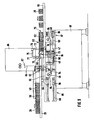
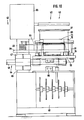
- Fig. 8 eine Vorrichtung (Verpackungsmaschine) für die Herstellung von Großpackungen (Gebinden) in perspektivischer Ansicht,
- Fig. 9 eine Seitenansicht zu der Vorrichtung gemäß Fig. 8,
- Fig. 10 eine gegenüber Fig. 9 um 90o versetzte Ansicht der Vorrichtung gemäß Fig. 8 und 9,
- Fig. 11 eine perspektivische Darstellung der Vorrichtung gemäß Fig. 8 bis 10 bei abgenommenen Teilen,
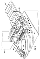
- Fig. 12 Einzelheiten der Vorrichtung in einer Darstellung entsprechend Fig. 8, bei vergrößertem Maßstab,
- Fig. 13 eine Einzelheit der Vorrichtung, nämlich eine Hubbühne, in perspektivischer Darstellung, vergrößert,
- Fig. 14 ein weiteres Detail, nämlich ein Falt- und Siegelwerkzeug, ebenfalls in perspektivischer Darstellung, vergrößert,
- Fig. 15 eine kuppelbare Antriebsverbindung für Teile der Vorrichtung in perspektivischer Darstellung,
- Fig. 16 die Einzelheiten gemäß Fig. 15 in eingekuppelter Stellung.
- 1 is a plant for the manufacture and packaging of paper handkerchiefs ("line") in a schematic plan view,
- 2 to 6 different folding positions of the outer wrapping of a large pack (container) in a perspective view,
- 7 shows a corner formation in the folded position according to FIG. 3 on a greatly enlarged scale,
- 8 shows a device (packaging machine) for the production of large packs (containers) in a perspective view,
- 9 is a side view of the device of FIG. 8,
- 10 is a 90 ° offset view of FIG. 9 of the device according to FIGS. 8 and 9,
- 11 is a perspective view of the device of FIGS. 8 to 10 with parts removed,
- 12 details of the device in a representation corresponding to FIG. 8, on an enlarged scale,
- 13 is a perspective view of a detail of the device, namely a lifting platform, enlarged,
- 14 shows a further detail, namely a folding and sealing tool, also in a perspective view, enlarged;
- 15 is a detachable drive connection for parts of the device in a perspective view,
- 16 shows the details according to FIG. 15 in the engaged position.
Die in den Zeichnungen dargestellten Ausführungsbeispiele befassen sich mit der Herstellung von Großpakkungen, sogenannten Gebinden 20 aus einer Mehrzahl von Kleinpackungen 21, im vorliegenden Falle Papier-Taschentuch-Packungen. Die Gebinde 20 werden durch eine hierfür eingerichtete Verpackungsmaschine, einem Gebindepacker 22) hergestellt. Dieser ist Teil einer Fertigungs- und Verpackungsanlage für Papier-Taschentücher, einer "Linie". Sie besteht aus einer Falzmaschine 23, einer Taschentuch-Verpackungsmaschine 24, einem dieser nachgeordneten Tape-Aggregat 25 zum Anbringen eines Verschlußstreifens an der Kleinpackung 21, einem Stapelkopf 26, dem nachfolgenden Gebindepacker 22 und einem hieran anschließenden Kartonpacker 27.The exemplary embodiments shown in the drawings deal with the production of large packages, so-called
Die Kleinpackungen 21 (Taschentuch-Packungen) werden bei dem vorliegenden Ausführungsbeispiel in zwei Bahnen gefertigt. Im Bereich des Stapelkopfes 26 wird eine gemeinsame Packungsreihe 28 aus gegebenenfalls mehreren übereinander angeordneten Kleinpackungen 21 gebildet. Diese wird dem Gebindepacker 22 durch einen Zuförderer 29 zugeführt.The small packs 21 (handkerchief packs) are produced in two lines in the present exemplary embodiment. In the area of the
Die Großpackungen (Gebinde 20) können unterschiedliche Abmessungen aufweisen, je nach der Anzahl der Kleinpakkungen 21 je Gebinde 20. Kleine Gebinde 20 bestehen aus sechs Kleinpackungen 21, große Gebinde 20 enthalten zum Beispiel vierundzwanzig Kleinpackungen. Diese sind zu einer regelmäßigen Gruppe 30 formiert aus neben- und übereinander ausgerichteten Kleinpackungen 21. Das Gebinde 20 wird durch eine Umhüllung 31 aus Kunststofffolie gebildet.The large packs (packs 20) can have different dimensions, depending on the number of
Der Gebindepacker 22 ist so ausgebildet, daß durch Auswechseln von Verpackungsorganen Gebinde 20 unterschiedlicher Größe gefahren werden können. Verpackungsorgane sind dabei Faltorgane für die Umhüllung 31, Schieber für den Transport der Gruppen 30, Förderorgane für Folienbahnen und Siegelorgane. Die Anzahl und Art der Verpackungsorgane ergibt sich aus der Gestaltung des Gebindes 20 bzw. den Schritten für die Herstellung der Umhüllung 31.The
Bei dem vorliegenden Ausführungsbeispiel wird die Umhüllung 31 in besonderer Weise gefaltet und führt zu einem in bezug auf die Umhüllung 31 besonderen Gebinde 20. Die Faltfolge ist in Fig. 2 bis Fig. 6 dargestellt.In the present exemplary embodiment, the wrapping 31 is folded in a special way and leads to a
Ein Zuschnitt für die Umhüllung 31 wird in vertikaler Ebene bereitgehalten und U-förmig um den Inhalt (Gruppe 30) herumgefaltet, und zwar durch Förderung der Gruppe 30 durch die Ebene des Zuschnitts hindurch. Dadurch an der Rückseite der Gruppe 30 zunächst überstehende, horizontal gerichtete Längslappen 32, 33 haben unterschiedliche Längen. Der obere Längslappen 32 ist so bemessen, daß die nach rückwärts weisende Längsseite des Gebindes 20 bzw. der Gruppe 30 auf voller Höhe abgedeckt wird. Dieser Längslappen 32 wird gegen die Rückseite der Gruppe 30 in die aufrechte Position gefaltet (Fig. 3). Ein unterer Randlappen 34 des Längslappens 32 wird bei diesem Faltvorgang auf die Oberseite des entsprechend bemessenen unteren Längslappens 33 aufgelegt und mit diesem durch Wärme und Druck versiegelt (Fig. 3 sowie Detail in Fig. 7). Ein dadurch gebildeter doppellagiger Randstreifen 35 wird sodann in eine aufrechte Position gefaltet bis zur Anlage an der Seitenfläche bzw. am oberen Längslappen 32 (Faltstellung gemäß Fig. 4).A blank for the wrapper 31 is held ready in the vertical plane and folded in a U shape around the contents (group 30) by conveying the
Im Bereich von Seitenflächen des Gebindes 20 stehen (zunächst) Faltlappen über die Gruppe 30 hinweg. Vordere Seitenlappen 36 und rückwärtige Seitenlappen 37 werden nacheinander gegen die Seitenfläche der Gruppe 30 gefaltet. Während des Transports der Gruppe 30 mit Umhüllung 31 wird der vordere Seitenlappen 36 gefaltet (Fig. 2). Erst später, nämlich nach Fertigstellung der rückseitigen Wandung der Umhüllung 31, wird durch entsprechende Bewegung eines Faltorgans der rückseitige Seitenlappen 37 gefaltet (Fig. 5). Sodann werden (dreieckförmige) Oberlappen 38 und Unterlappen 39 zur Anlage an den Seitenflächen bzw. an den Seitenlappen 36, 37 umgefaltet (Fig. 6). Oberlappen 38 und Unterlappen 39 einerseits sowie Seitenlappen 36 und 37 andererseits werden durch Wärme und Druck miteinander versiegelt.In the area of side surfaces of the
Die für diesen Falt- und Siegelvorgang erforderlichen Mittel bilden zusammen einen kompletten Satz der Verpackungsorgane. Dem Gebindepacker 22 sind mehrere Sätze von Verpackungsorganen zugeordnet, wobei diese zur Anpassung an unterschiedliche Formate der Gebinde 20 zweckmäßigerweise komplett austauschbar sind.The means required for this folding and sealing process together form a complete set of packaging elements. The
Der hier dargestellte und beschriebene Gebindepacker 22 ist für die Aufnahme von zwei Sätzen 40, 41 der Verpackungsorgane eingerichtet. Diese Sätze 40 und 41 befinden sich in einer Verpackungsstation 42. Jeweils einer der Sätze, bei dem in Fig. 1 gezeigten Beispiel der Satz 40, befindet sich in der Verpackungsstellung 43. Dieser werden die Kleinpackungen 21 bzw. die Gruppen 30 zugeführt.The
Bei dem vorliegenden Ausführungsbeispiel sind die Sätze 40 und 41 abnehmbar mit einer verstellbaren Tragvorrichtung nämlich einem Drehwerk verbunden, welches die Sätze 40, 41 durch Drehbewegung alternativ in die Verpackungsstellung 43 oder in eine Auswechselstellung 44 bewegt. Im Bereich der letztgenannten werden die Verpackungsorgane des Satzes 41 vorzugsweise komplett als Einheit ausgetauscht.In the present exemplary embodiment, the
Das Drehwerk besteht hier aus einer aufrechten Tragsäule 45, die fest mit einem Maschinengestell bzw. einem Antriebsgehäuse 46 verbunden ist. Auf der Tragsäule 45 ist eine Traverse 47 drehbar gelagert. An den Enden derselben sind Halterungen für die Sätze 40, 41 angebracht, nämlich quergerichete Tragstangen 48. Auf diesen horizontal gerichteten, mit der Traverse 47 um die Tragsäule drehbaren Tragstangen sind die Verpackungsorgane der Sätze 40, 41 abnehmbar, nämlich abziehbar, angebracht.The slewing gear here consists of an
Die Packungsreihe 28 wird etwa mittig zur Verpackungsstation 42 dieser zugeführt. Der Zuförderer 29 ist im vorliegenden Falle mittig zur Tragsäule 45 ausgerichtet. Eine der Größe des Gebindes entsprechende Anzahl von Kleinpackungen 21 - zu mehreren übereinander angeordnet - wird durch einen quer bewegbaren, längs eines Viertelkreises wirkenden Schwenkschieber 49 erfaßt und längs eines Viertelkreises auf einer plattenförmigen Oberbahn 50 in die Verpackungsstellung 43 gefördert. Der Schwenkschieber 49 ist mit einer die Oberbahn 50 bildenden Platte verbunden.The
Am Ende der Oberbahn 50 gelangt die Gruppe 30 der Kleinpackungen 21 in den Bereich einer Hubbühne 51 deren wichtigste Aufgabe besteht darin, die Gruppe aus der Ebene der Oberbahn 50 abzusenken auf das Niveau einer Hauptbahn 52. Diese besteht aus einer der Höhe nach gegenüber der Oberbahn 50 versetzten Bahnplatte 53. Auf der Hauptbahn 52 sind die Verpackungsorgane angeordnet bzw. wirksam.At the end of the
Die Hubbühne 51 besteht aus einer Plattform 54, auf der die Gruppe 30 durch den Schwenkschieber 49 aufgeschoben wird. Die Plattform 54 wird durch drei Teilplattformen gebildet, die auf einem unteren, quergerichteten Tragprofil 55 abgestützt sind. Die Oberseite der Hubbühne 51 wird durch einen Plattformdeckel 56 gebildet, der sich auf die Oberseite der Gruppe 30 auflegt. Der Plattformdeckel 56 ist mit einer oberen Querstange 57 verbunden. Diese sowie das untere Tragprofil 55 sind durch aufrechte Führungsstangen 58 miteinander verbunden. Die Führungsstangen 58 sind in feststehenden Gleitlagern 59 an der Bahnplatte 53 auf- und abbewegbar.The
Eine weitere Besonderheit der Hubbühne 51 besteht darin, daß deren Seitenwände 60 querbewegbar sind um einen seitlichen Druck auf die Kleinpackungen 21 der Gruppe 30 auszuüben. Dadurch ist es möglich, die Gruppe 30 als Inhalt des Gebindes 20 auf eine exakte, stets wiederkehrende Abmessung einzustellen. Die Seitenwände 60 sind zu diesem Zweck schwenkbar gelagert an Schwenkarmen 61, die über ein Schwenklager 62 mit dem unteren Tragprofil 55 verbunden sind. Bei der Aufnahme einer Gruppe 30 sind die Seitenwände 60 auseinanderbewegt. Danach werden die Seitenwände 60 aufeinander zu bewegt unter Zusammendrücken der Kleinpackungen 21.Another special feature of the
In der oberen Ausgangsstellung (Fig. 12) ist die Hubbühne 51 mit der Plattform 54 auf die Oberbahn 50 ausgerichtet. Nach Aufnahme der Gruppe 30 wird die Hubbühne 51 abgesenkt, bis die Plattform 54 auf die Hauptbahn 52 ausgerichtet ist.In the upper starting position (FIG. 12), the
In dieser unteren Stellung der Bühne 51 wird die Gruppe 30 ausgestoßen, und zwar durch einen Abschieber 63. Dieser tritt durch die Hubbühne 51 hindurch unter Mitnahme der Gruppe 30. Der Abschieber 63 wird durch Schieberstangen 64 geführt, die sich unterhalb der Bahnplatte 53 befinden, während sich der Abschieber 63 selbst oberhalb derselben bewegt.In this lower position of the
Die Gruppe 30 tritt beim Verlassen der Hubbühne 51 durch die Ebene einer Folienbahn 65 hindurch. Diese wird in aufrechter Ebene durch einen Folienapparat 66 bereitgehalten. Die Folienbahn 65 wird durch die Gruppe 30 mitgenommen, wobei ein abgemessener Zuschnitt zur Bildung der Umhüllung 31 durch Trennmesser 67 von der Folienbahn 65 abgetrennt wird. Der Zuschnitt legt sich U-förmig um die Gruppe 30 herum und wird sodann in der oben beschriebenen Weise gefaltet (Fig. 2 - 6).The
Diese Faltung erfolgt im Bereich einer Faltstation 68. Während der Förderbewegung der Gruppe 30 mit Umhüllung 31 werden die in Bewegungsrichtung vornliegenden Seitenlappen 36 durch Seitenfalter 69 zu beiden Seiten der Bewegungsbahn der Gruppe 30 gefaltet. Die Seitenfalter werden zu diesem Zweck aus einer vornliegenden Postition der Gruppe 30 entgegenbewegt, bis in den Bereich der Seitenlappen 36. Diese werden durch die Seitenfalter 69 gefaltet) wobei anschließend die Seitenfalter 69 mit der Gruppe 30 weitergefördert werden.This folding takes place in the area of a
Die Gruppe 30 mit Umhüllung 31 (und mit den sich in Faltstellung befindenden Seitenfalter 69) wird bis zur Anlage an eine Gebindereihe 70 aus bereits weitgehend fertiggefalteten Gebinden 20 gefördert unter Weiterbewegung der Gebindereihe 70 um einen Bewegungstakt entsprechend der Abmessung eines Gebindes 20. Der Abschieber 63 kehrt sodann in die Ausgangsstellung zurück.The
Die Seitenfalter 69 zu beiden Seiten der Gebinde 20 werden währenddessen in der zur Bewegung der Gebinde 20 entgegengesetzten Richtung weiterbewegt, wobei die Seitenfalter 69 an der noch nicht gefalteten Rückseite der Umhüllung 31 aus den Bereich der Gruppe 30 austreten (Position gemäß Fig. 2).The
Nun kann die Faltung der Längslappen 32, 33 unter Bildung des Randstreifens 35 erfolgen (Faltvorgänge gemäß Fig. 3 und 4). Für die Abwärtsfaltung des oberen Längslappens 32 ist ein Oberfalter 71 vorgesehen, der hier aus einer verhältnismäßig dünnen Wandung besteht mit einem unteren abgewinkelten Schenkel 72. Dieser drückt den Randlappen 32 auf den unteren, abstehenden Längslappen 33.Now the
Der Längslappen 33 liegt dabei auf einem Unterfalter 73 auf, der zugleich als Siegelwerkzeug dient und deshalb beheizbar ist. Der Unterfalter 73 ist als winkelförmiges Profilstück ausgebildet (Fig. 14). In der Ausgangsstellung liegt der etwa horizontal gerichtete Randstreifen 35 auf einem aufwärtsgerichteten Schenkel 74 des Unterfalters 73 auf. Nach Verbindung des Randlappens 34 mit dem Längslappen 33 wird der Randstreifen 35 durch Aufwärtsbewegung des Unterfalters 73 gegen die rückwärtige Längsfläche der Umhüllung 31 bzw. gegen den Längslappen 32 gedrückt und mit diesem versiegelt.The
Oberfalter 71 und Unterfalter 73 sind lediglich auf- und abbewegbar. Der Oberfalter 71 ist über Haltestangen 75 mit einem sich oberhalb der Faltstation 68 quer erstreckenden Tragprofil 76 verbunden. Dieses ist über seitliche, aufrechte Führungsstangen 77 bewegbar auf der Bahnplatte 53 abgestützt. Die Führungsstangen 77 sind in Gleitführungen 78 in der Bahnplatte 53 auf- und abbewegbar zur Durchführung der Faltbewegung.The
Der Unterfalter ist in Ausgangsstellung unterhalb der Bahnplatte 53 bzw. der Hauptbahn 50 gelagert, so daß der Schenkel 74 mit der Unterseite des Gebindes 20 bündig liegt. Der Unterfalter 73 ist seitlich an einer Profilstange 79 angebracht, die ihrerseits an den Enden mit Führungsstangen 80 verbunden ist. Diese wiederum sind in aufrechter Anordnung gleitend in Gleitführungen 81 an bzw. in der Bahnplatte 53 gelagert. Der Unterfalter 73 führt aufgrund seiner Funktion nur geringe Hubbewegungen aus.The lower folder is mounted in the starting position below the
Nach Durchführung der vorstehenden Faltvorgänge wird die nächste Gruppe 30 mit Umhüllung 31 zugeführt, wobei die Seitenfalter 69 in der beschriebenen Weise mit dieser nachfolgenden Gruppe 30 mit laufen unter Umfalten der Seitenlappen 36. Die Relativstellung der Seitenfalter 69 ist derart, daß in der Endstellung ein in Bewegungsrichtung vornliegender Bereich der Seitenfalter 69 in den Bereich der Seitenflächen des davorliegenden Gebindes 20 in der Gebindereihe 70 eintreten. Dabei wird der in Förderrichtung rückseitige Seitenlappen 37 umgefaltet (Fig. 5).After the above folding operations have been carried out, the
Oberlappen 38 und Unterlappen 39 werden während des Weitertransports der Gebindereihe 70 gefaltet durch feststehende, unbewegliche Faltorgane an sich bekannter Art, nämlich durch sogenannte Faltweichen (nicht gezeigt). Diese sind als feststehende Wände ausgebildet, die seitlich neben der Bewegungsbahn der Gebinde 20 angeordnet sind und durch kurvenförmige Gestaltung einer Faltkante während der Bewegung der Gebinde 20 nacheinander Oberlappen 38 und Unterlappen 39 falten.
Wenn die Faltform gemäß Fig. 6 erreicht ist, wird durch ein plattenförmiges Siegelwerkzeug 82 die Seitenfläche gesiegelt, nämlich die überlappenden Bereiche von Oberlappen 38 und Unterlappen 39 miteinander. Danach ist das Gebinde 20 fertiggestellt. Es kann nun in geeigneter Weise abtransportiert werden über eine feststehende Abförderbahn 83.When the folded shape according to FIG. 6 is reached, the side surface is sealed by a plate-shaped
Die Seitenfalter 69 sind in ähnlicher Weise gelagert wie Oberfalter 71 und Unterfalter 73. Ein Tragprofil 90 erstreckt sich in Querrichtung unterhalb der Bahnplatte 53. An den Enden desselben sind aufrechte Winkelprofile angebracht, die jeweils die quaderförmigen Seitenfalter 69 aufnehmen. Das Tragprofil 90 wird unterhalb der Bahnplatte 53 in Bewegungsrichtung der Gebinde 20 hin- und hergehend angetrieben.The
Die vorstehend beschriebenen Falt-, Förder- und Siegelorgane bilden einen (kompletten) Satz 40, 41 an Verpackungsorganen. Für andere Arten von Verpackungen können die Sätze 40, 41 hinsichtlich der Art und Anzahl der Verpackungsorgane modifiziert sein.The folding, conveying and sealing elements described above form a (complete) set 40, 41 of packaging elements. For other types of packaging, the
Die für einen Formatwechsel der herzustellenden Verpackungen (Gebinde 20) auszutauschenden Verpackungsorgane sind bei dem vorliegenden Ausführungsbeispiel auf einem gemeinsamen Träger angeordnet, nämlich auf der Bahnplatte 53. Mit dieser ist auch die plattenförmige Oberbahn 50 mit den daran angebrachten Organen, insbesondere dem Schwenkschieber 49, verbunden.In the present exemplary embodiment, the packaging elements to be exchanged for changing the format of the packaging (bundle 20) to be produced are arranged on a common carrier, namely on the
Der gemeinsame Träger (Bahnplatte 53) ist leicht abnehmbar auf Halteorganen in der Verpackungsstation 42 gelagert. Es sind die mit der Traverse 47 verbundenen, horizontal gerichteten Tragstangen 48, auf denen die Bahnplatte 53 mit an der Unterseite derselben angeordneten Lagerstücken 84 verschiebbar und damit abziehbar, gelagert ist. Zum Auswechseln eines kompletten Satzes 40, 41 wird die Bahnplatte 53 im Bereich der Auswechselstation 44 von den Tragstangen 48 heruntergezogen und gegen einen anderen Satz ausgetauscht.The common carrier (web plate 53) is easily removable and mounted on holding members in the
Die bewegbaren Verpackungsorgane eines Satzes 40, 41 werden beim Austausch bzw. bei der Bewegung eines Satzes 40, 41 in die Verpackungsstellung 43 selbsttätig mit ortsfesten, nicht austauschbaren Antrieben gekoppelt. Bei dem vorliegenden Beispiel sind an dem Maschinengestell bzw. am Antriebsgehäuse 46 an der Oberseite Antriebsorgane 85, 86, 87 für verschiedene bewegbare Verpackungsorgane angeordnet. Diese Antriebsorgane 85, 86, 87 bestehen im vorliegenden Falle aus Antriebsstücken 88, die gleitend auf (zwei) feststehenden Gleitstangen 89 verschiebbar sind. Die Antriebsstücke 88 werden durch Getriebe, zum Beispiel Kurvenscheiben, im Inneren des Antriebsgehäuses 46 angetrieben.The movable packaging members of a
Die hier beispielsweise in Fig. 11 gezeigten Antriebsorgane sind dem Abschieber 63 (Antriebsorgan 85), den Seitenfaltern 69 (Antriebsorgan 86) und den Siegelwerkzeugen 82 (Antriebsorgan 87) zugeordnet. Darüber hinaus sind Huborgane 91 vorgesehen, die ebenfalls am bzw. auf dem Antriebsgehäuse 46 gelagert und auf- und abbewegbar sind (Fig. 15, 16). Ein derartiges Huborgan 91 ist dem Oberfalter 71 sowie dem Unterfalter 73 zugeordnet. Bei dem gezeigten Ausführungsbeispiel ist eine Hubstange 92 am oberen Ende mit einem Kupplungskopf 93 versehen. Dieser wird selbsttätig durch die Bewegung eines Satzes 40, 41 in die und aus der Verpackungsstellung 43 mit dem zu betätigenden Verpackungsorgan gekoppelt. Bei dem hier gezeigten Ausführungsbeispiel ist zu diesem Zweck an dem Verpackungsorgan eine drehbare Kupplungsrolle 94 angebracht. Diese tritt in eine Kulissenführung 95 seitlich am Kupplungskopf 93 ein. Wie aus Fig. 16 ersichtlich, wird so in der Arbeitsstellung der Verpackungsorgane eine formschlüssige Verbindung zur Übertragung von Antriebsbewegungen geschaffen. In analoger Weise sind auch die Kupplungen für die Antriebsorgane 85, 86, 87 ausgebildet.The drive elements shown here for example in FIG. 11 are assigned to the pusher 63 (drive element 85), the side folders 69 (drive element 86) and the sealing tools 82 (drive element 87). In addition, lifting
Der Transport der Gebinde 20 bzw. Gruppen 30 nach Verlassen der Hubbühne 51 erfolgt unter einer Oberführung in Gestalt eines Bahndeckels 96. Dieser erstreckt sich vom Bewegungsbereich der Hubbühne 51 an bis zur Fertigstellung der Gebinde 20 mit einem der exakten Abmessung der Gebinde 20 entsprechenden Abstand von der Bahnplatte 53. Für den Durchtritt von Faltorganen etc. sind Öffnungen im Bahndeckel 96 vorgesehen.The transport of the
Der Folienapparat 66 mit Trennmesser 57 und Förderrollen ist bei dem vorliegenden Ausführungsbeispiel fest mit der Tragsäule 45 verbunden, bleibt demnach stets in der Verpackungsstellung 43. Alternativ kann der Folienapparat 66 austauschbar angeordnet sein oder drehbar mit den beweglichen Sätzen 40, 41 sein. Dadurch ist es möglich, zwei unterschiedliche Ausführungen des Folienapparats vorzusehen. Mit dem Wechsel des Satzes 40, 41 kann auch der Folienapparat gewechselt werden.The
Des weiteren sind Alternativausführungen für die Lagerung und Auswechselbarkeit der Sätze 40, 41 möglich.Furthermore, alternative designs for the storage and interchangeability of the
Claims (21)
Priority Applications (1)
| Application Number | Priority Date | Filing Date | Title |
|---|---|---|---|
| EP90124420A EP0424991B1 (en) | 1989-03-09 | 1990-02-21 | Method and device for the packaging of products |
Applications Claiming Priority (2)
| Application Number | Priority Date | Filing Date | Title |
|---|---|---|---|
| DE3907615 | 1989-03-09 | ||
| DE3907615A DE3907615A1 (en) | 1989-03-09 | 1989-03-09 | DEVICE (PACKING MACHINE) FOR PACKING ITEMS OF DIFFERENT SIZES |
Related Child Applications (1)
| Application Number | Title | Priority Date | Filing Date |
|---|---|---|---|
| EP90124420.2 Division-Into | 1990-02-21 |
Publications (2)
| Publication Number | Publication Date |
|---|---|
| EP0386524A1 true EP0386524A1 (en) | 1990-09-12 |
| EP0386524B1 EP0386524B1 (en) | 1994-10-12 |
Family
ID=6375915
Family Applications (2)
| Application Number | Title | Priority Date | Filing Date |
|---|---|---|---|
| EP90103316A Expired - Lifetime EP0386524B1 (en) | 1989-03-09 | 1990-02-21 | Device for packaging objects of different size |
| EP90124420A Expired - Lifetime EP0424991B1 (en) | 1989-03-09 | 1990-02-21 | Method and device for the packaging of products |
Family Applications After (1)
| Application Number | Title | Priority Date | Filing Date |
|---|---|---|---|
| EP90124420A Expired - Lifetime EP0424991B1 (en) | 1989-03-09 | 1990-02-21 | Method and device for the packaging of products |
Country Status (6)
| Country | Link |
|---|---|
| US (2) | US5056294A (en) |
| EP (2) | EP0386524B1 (en) |
| JP (2) | JP2565578B2 (en) |
| BR (1) | BR9001111A (en) |
| CA (1) | CA2011161C (en) |
| DE (3) | DE3907615A1 (en) |
Cited By (3)
| Publication number | Priority date | Publication date | Assignee | Title |
|---|---|---|---|---|
| US6022871A (en) * | 1992-07-22 | 2000-02-08 | Novartis Corporation | Oxadiazine derivatives |
| US6376487B1 (en) | 1992-07-22 | 2002-04-23 | Syngenta Investment Corp. | Oxadiazine derivatives |
| ITFI20090159A1 (en) * | 2009-07-21 | 2011-01-22 | Ohg Ciolini S R L | PLANT FOR PACKAGING AND BURNING OF PRODUCTS. |
Families Citing this family (46)
| Publication number | Priority date | Publication date | Assignee | Title |
|---|---|---|---|---|
| DE4138138C2 (en) * | 1991-10-19 | 2003-06-12 | Focke & Co | Device for producing large packs |
| IT1257754B (en) * | 1992-03-03 | 1996-02-13 | Gd Spa | METHOD FOR THE REALIZATION OF CIGARETTE PACKS |
| JP2582860Y2 (en) * | 1992-06-29 | 1998-10-15 | 北海製罐株式会社 | Cylindrical bag packaging |
| GB2282987B (en) * | 1993-10-15 | 1997-05-07 | Field Group Plc | Performing operations on carton blanks |
| DE4411358B4 (en) * | 1994-03-31 | 2005-10-27 | Focke & Co.(Gmbh & Co. Kg) | Device for producing packaging from in particular thin plastic film |
| ES2122867B1 (en) * | 1995-05-12 | 1999-07-01 | Construcciones Metalicas J Bar | AUTOMATIC INSTALLATION FOR PACKAGING WITH THERMO-RETRACTABLE FILM. |
| DE19521476C2 (en) * | 1995-06-13 | 1999-05-27 | Focke & Co | Device for the thermal sealing or welding of plastic films |
| US5996316A (en) * | 1997-04-25 | 1999-12-07 | The Coca-Cola Company | System and method for order packing |
| DE19736730A1 (en) * | 1997-08-22 | 1999-02-25 | Focke & Co | Unit package for cigarette packs |
| US6000195A (en) * | 1998-04-27 | 1999-12-14 | Tetra Laval Holdings & Finance, Sa | Packaging machine with capability to convert to different carton cross-sections |
| FI106015B (en) * | 1999-04-30 | 2000-11-15 | Pussikeskus Oy | Packing device and method of packing flat items such as books |
| US6668520B1 (en) * | 2000-06-16 | 2003-12-30 | Standard Knapp Inc. | Modular sliding door grid |
| DE10102926A1 (en) * | 2001-01-23 | 2002-07-25 | Focke & Co | Process for making cigarette packs |
| US6629404B2 (en) | 2001-02-01 | 2003-10-07 | Hallmark Cards Incorporated | Method of and system for packaging articles |
| DE10115563A1 (en) * | 2001-03-28 | 2002-10-02 | Focke & Co | Packaging machine for cigarettes |
| EP1281789B1 (en) * | 2001-07-31 | 2006-05-31 | Kabushiki Kaisha Kobe Seiko Sho (Kobe Steel, Ltd.) | A plated copper alloy material and process for production thereof |
| WO2003033816A1 (en) * | 2001-10-16 | 2003-04-24 | International Paper Company | Reinforced packaging webs and method |
| US7279198B1 (en) * | 2001-10-16 | 2007-10-09 | Thilmany Llc | Method for extrusion coating a lightweight web |
| US6656401B1 (en) | 2001-10-16 | 2003-12-02 | International Paper Company | Method for extrusion coating multiple webs |
| US7184855B2 (en) | 2002-03-13 | 2007-02-27 | Stingel Iii Frederick J | Automated container storage and delivery system |
| ATE281349T1 (en) * | 2002-04-09 | 2004-11-15 | Fuji Photo Film Co Ltd | METHOD AND DEVICE FOR AUTOMATICALLY PACKAGING ITEMS |
| US6871116B2 (en) | 2002-10-17 | 2005-03-22 | Vertique, Inc. | Determining pallet case configurations for placement by a robot |
| EP1459983A1 (en) * | 2003-03-19 | 2004-09-22 | TOPACK Verpackungstechnik GmbH | Method for wrapping packages for tobacco industry products |
| EP1535844B1 (en) * | 2003-11-28 | 2007-01-03 | KPL Packaging S.p.A. Società Unipersonale | A packaging machine for wrapping products in related wrapping sheets made of heat-sealable material |
| ITBO20050328A1 (en) * | 2005-05-06 | 2005-08-05 | Gd Spa | METHOD FOR THE EXECUTION OF A BRAND CHANGE IN AN AUTOMATIC PRODUCTION COMPLEX FOR SMOKE ITEMS PROCESSING |
| US7506486B2 (en) | 2005-07-29 | 2009-03-24 | Infinity Machine & Engineering Corp. | Modular packaging system |
| DE102005053436B3 (en) * | 2005-11-09 | 2007-03-15 | Maschinenbau Oppenweiler Binder Gmbh & Co. Kg | Folding machine, has stacking device arranged below cross-cut folding knife, and triple-cutter module arranged downstream to support, where module and support are arranged at pivot mounting that is rotatable around specified degrees |
| ITPS20060002A1 (en) * | 2006-01-26 | 2007-07-27 | Pietro Donati | MACHINE FOR PACKAGING THE PRODUCT IN CASES WITH WORKTOP AND VARIABLE INCLINATION LOAD |
| US7637077B2 (en) * | 2006-05-09 | 2009-12-29 | Illinois Tool Works Inc. | Applicating machine |
| US7614202B2 (en) * | 2007-11-27 | 2009-11-10 | Atlas Vac Machine Co., Llc | Sealer and interchangeable tooling therefor |
| CA2634695C (en) | 2008-07-18 | 2009-08-04 | The Procter & Gamble Company | Assembling a packaged bundle using an adjustable multi-shelved product transporter |
| DE102008037708B4 (en) * | 2008-08-14 | 2014-05-28 | Krones Aktiengesellschaft | Method and device for treating beverage containers |
| DE102009025568A1 (en) * | 2009-06-13 | 2010-12-16 | Hauni Maschinenbau Ag | Device and method for the successive emptying of containers filled with rod-shaped products |
| DE102011001532A1 (en) * | 2010-07-30 | 2012-02-02 | Krones Aktiengesellschaft | Storage device for containers and method for storing containers |
| US8650843B2 (en) * | 2011-02-04 | 2014-02-18 | Alpma Alpenland Maschinenbau Gmbh | Method of packaging products |
| DE102011102696A1 (en) * | 2011-05-28 | 2012-11-29 | Andreas Dittrich | Device for mechanically forming rod-shaped tobacco product packing unit, has several toolkits which are assigned to grouping device and packaging device and are mutually exchangeable and differently trained |
| CA2839520C (en) | 2011-06-15 | 2017-06-13 | The Procter & Gamble Company | Methods of processing rolls of fibrous materials |
| ITBO20110718A1 (en) * | 2011-12-15 | 2013-06-16 | So Te Ma Pack S R L | EQUIPMENT FOR REALIZING A RESPECTIVE PACKAGE. |
| WO2013088412A2 (en) * | 2011-12-15 | 2013-06-20 | So.Te.Ma. Pack S.R.L. | An apparatus for making a respective package. |
| MX2014015255A (en) | 2012-06-14 | 2015-03-05 | Procter & Gamble | Method of transporting rolled products as well as package of rolled products. |
| JP6719145B1 (en) * | 2019-05-13 | 2020-07-08 | 日本ポリスター株式会社 | Packaging method, packaging device, package, and closing device for simple closing part of package |
| DE102019120788A1 (en) * | 2019-08-01 | 2021-02-04 | Khs Gmbh | Device and process for the production of containers from individual packs |
| EP4149842A1 (en) * | 2020-08-04 | 2023-03-22 | LOESCH Verpackungstechnik GmbH + Co. KG | Apparatus for packaging slab-form or cuboidal products |
| CN112124710B (en) * | 2020-10-21 | 2022-04-12 | 深圳市优德油脂工程技术有限公司 | Automatic intelligent packaging line for massive edible oil |
| CN113415487B (en) * | 2021-07-26 | 2023-11-14 | 东光县恒信包装机械厂 | Double-sided baling press of carton |
| CN113753323B (en) * | 2021-09-07 | 2022-09-16 | 合肥美萨智能装备有限公司 | Automatic bag supply structure based on full-automatic packaging machine |
Citations (2)
| Publication number | Priority date | Publication date | Assignee | Title |
|---|---|---|---|---|
| FR731713A (en) * | 1931-02-24 | 1932-09-06 | Sapal Plieuses Automatiques | Packing machine |
| GB911273A (en) * | 1960-05-17 | 1962-11-21 | Drohmann Gmbh C | Wrapping machine |
Family Cites Families (33)
| Publication number | Priority date | Publication date | Assignee | Title |
|---|---|---|---|---|
| NL111469C (en) * | 1900-01-01 | |||
| GB244493A (en) * | 1925-12-15 | 1926-11-11 | Sig Schweiz Industrieges | Improved machine for wrapping articles in two or more coverings |
| GB402052A (en) * | 1932-02-20 | 1933-11-23 | Sapal Plieuses Automatiques | Improvements in or relating to wrapping machines |
| DE911273C (en) * | 1940-02-06 | 1954-05-13 | Telefunken Gmbh | Method for wireless distance determination |
| US2540430A (en) * | 1948-07-17 | 1951-02-06 | Package Machinery Co | Gum wrapping machine |
| DE947538C (en) * | 1948-08-10 | 1956-08-16 | Mach Automatiques Bardet | Machine for packing several similar, stacked bodies |
| US2651578A (en) * | 1949-12-13 | 1953-09-08 | Stephen Bodolay Inc | Package and method of making it |
| DE1062619B (en) * | 1955-01-13 | 1959-07-30 | Hesser Ag Maschf | Device for closing the wrapping cover on both sides of a machine for wrapping rod-shaped objects |
| CH327555A (en) * | 1955-10-28 | 1958-01-31 | Sapal Plieuses Automatiques | Packaging process for rectangular plates |
| DE1169835B (en) * | 1960-07-07 | 1964-05-06 | Hauni Werke Koerber & Co Kg | Wrapping machine for wrapping cigarette packs |
| US3185973A (en) * | 1962-11-28 | 1965-05-25 | Hewlett Packard Co | Differential transformers |
| CH412691A (en) * | 1964-06-16 | 1966-04-30 | Sig Schweiz Industrieges | Device for wrapping objects |
| US3372526A (en) * | 1965-01-22 | 1968-03-12 | Scandia Packaging Mach | Wrapping mechanism |
| CH426609A (en) * | 1965-02-26 | 1966-12-15 | Sapal Plieuses Automatiques | Method for rolling in multiple closing folds on flat objects |
| US3507091A (en) * | 1966-11-23 | 1970-04-21 | Brown & Williamson Tobacco | Overwrapping machine |
| US3609646A (en) * | 1969-03-06 | 1971-09-28 | Fargo Mfg Co Inc | Connector assembly |
| DE2237948C3 (en) * | 1972-08-02 | 1975-01-09 | Packautomatic Gmbh & Co Kg, 5828 Ennepetal | Folding device on packaging machines |
| JPS5141743Y2 (en) * | 1973-01-30 | 1976-10-09 | ||
| DE2331401C3 (en) * | 1973-06-20 | 1980-05-29 | Josef Kiener Maschinen- Und Apparatebau, 8942 Ottobeuren | Machine for banding objects |
| CH565679A5 (en) * | 1973-11-12 | 1975-08-29 | Involvo Ag | Packing and feeding machine - has open forming dies with two vertical walls and pivoting levers on transport device |
| DE2626459C3 (en) * | 1976-06-12 | 1982-12-23 | Kronseder, Hermann, 8404 Wörth | Closing device for bottles |
| JPS53116993A (en) * | 1977-03-19 | 1978-10-12 | Tokyo Jidou Kikai Seisakushiyo | Accumulative packing mfethod of and apparatus for marchandise |
| JPS5338492A (en) * | 1977-06-28 | 1978-04-08 | Glory Ltd | Apparatus of feeding packing pater for coin packing machine |
| US4341057A (en) * | 1978-09-22 | 1982-07-27 | Pet, Inc. | Wrapping machine |
| IT1199031B (en) * | 1981-07-17 | 1988-12-21 | Ireneo Bozza | WRAPPING-PACKING MACHINE FOR THE PACKAGING OF PACKAGES OF BOXES OR PRODUCTS |
| JPS58160202A (en) * | 1982-01-15 | 1983-09-22 | ザ・ミ−ド・コ−ポレ−シヨン | Packer |
| US4569180A (en) * | 1984-03-02 | 1986-02-11 | Luigi Russo | System for reversing the sequential position of the operative units in automatic packaging machinery |
| DE3444950A1 (en) * | 1984-12-10 | 1986-06-12 | Otto Hänsel GmbH, 3000 Hannover | METHOD FOR PRODUCING A PACKAGING FOR TABLETOUS GOODS, IN PARTICULAR FOR CHOCOLATE TABLETS, AND THE TABLETACK PACKAGED THEREFORE |
| CH666010A5 (en) * | 1985-03-11 | 1988-06-30 | Sig Schweiz Industrieges | PACKAGING FOR A TABLED PRODUCT, IN PARTICULAR A CHOCOLATE TABLE. |
| DE3512462A1 (en) * | 1985-04-04 | 1986-12-04 | H & K Verpackungstechnik GmbH, 4600 Dortmund | MACHINE FOR PACKING AND UNPACKING BOTTLES, MULTIPACK PACKAGING IN OR FROM KAESTEN |
| DE3605864C1 (en) * | 1986-02-24 | 1987-06-19 | Hassia Verpackung Ag | Packing machine with foil tape run for the continuous cyclical shaping, filling, closing and at least grouping of cups |
| JPS63294317A (en) * | 1987-01-26 | 1988-12-01 | Shimizu Tekkosho:Goushi | Body seal machine |
| FR2615166B1 (en) * | 1987-05-12 | 1989-08-11 | Sapal Plieuses Automatiques | PROCESS FOR PACKAGING A PRODUCT AND DEVICE FOR CARRYING OUT SAID PROCESS |
-
1989
- 1989-03-09 DE DE3907615A patent/DE3907615A1/en not_active Withdrawn
-
1990
- 1990-02-21 DE DE59007412T patent/DE59007412D1/en not_active Expired - Fee Related
- 1990-02-21 EP EP90103316A patent/EP0386524B1/en not_active Expired - Lifetime
- 1990-02-21 EP EP90124420A patent/EP0424991B1/en not_active Expired - Lifetime
- 1990-02-21 DE DE59007759T patent/DE59007759D1/en not_active Expired - Fee Related
- 1990-02-28 CA CA002011161A patent/CA2011161C/en not_active Expired - Fee Related
- 1990-03-07 US US07/489,640 patent/US5056294A/en not_active Expired - Fee Related
- 1990-03-08 BR BR909001111A patent/BR9001111A/en not_active IP Right Cessation
- 1990-03-09 JP JP2056781A patent/JP2565578B2/en not_active Expired - Fee Related
-
1993
- 1993-07-28 US US08/097,913 patent/US5365721A/en not_active Expired - Fee Related
-
1996
- 1996-04-26 JP JP8106888A patent/JP2768925B2/en not_active Expired - Fee Related
Patent Citations (2)
| Publication number | Priority date | Publication date | Assignee | Title |
|---|---|---|---|---|
| FR731713A (en) * | 1931-02-24 | 1932-09-06 | Sapal Plieuses Automatiques | Packing machine |
| GB911273A (en) * | 1960-05-17 | 1962-11-21 | Drohmann Gmbh C | Wrapping machine |
Cited By (5)
| Publication number | Priority date | Publication date | Assignee | Title |
|---|---|---|---|---|
| US6022871A (en) * | 1992-07-22 | 2000-02-08 | Novartis Corporation | Oxadiazine derivatives |
| US6376487B1 (en) | 1992-07-22 | 2002-04-23 | Syngenta Investment Corp. | Oxadiazine derivatives |
| US6627753B1 (en) | 1992-07-22 | 2003-09-30 | Syngenta Investment Corporation | Oxadiazine derivatives |
| US7655650B2 (en) | 1992-07-22 | 2010-02-02 | Syngenta Corporation | Oxadiazine derivatives |
| ITFI20090159A1 (en) * | 2009-07-21 | 2011-01-22 | Ohg Ciolini S R L | PLANT FOR PACKAGING AND BURNING OF PRODUCTS. |
Also Published As
| Publication number | Publication date |
|---|---|
| JPH03148409A (en) | 1991-06-25 |
| CA2011161C (en) | 2000-09-05 |
| CA2011161A1 (en) | 1990-09-09 |
| EP0386524B1 (en) | 1994-10-12 |
| JP2565578B2 (en) | 1996-12-18 |
| BR9001111A (en) | 1991-03-05 |
| DE59007759D1 (en) | 1995-01-05 |
| DE3907615A1 (en) | 1990-09-13 |
| DE59007412D1 (en) | 1994-11-17 |
| US5365721A (en) | 1994-11-22 |
| EP0424991B1 (en) | 1994-11-23 |
| JP2768925B2 (en) | 1998-06-25 |
| JPH08268408A (en) | 1996-10-15 |
| EP0424991A1 (en) | 1991-05-02 |
| US5056294A (en) | 1991-10-15 |
Similar Documents
| Publication | Publication Date | Title |
|---|---|---|
| EP0386524B1 (en) | Device for packaging objects of different size | |
| DE2425969C2 (en) | ||
| EP0275481B1 (en) | Method and device for packaging paper handkerchiefs | |
| DE2440006A1 (en) | PROCESS AND DEVICE FOR MANUFACTURING AND FILLING FOLDABLE BOXES FROM FOLDABLE MATERIAL, PREFERABLY FOR CIGARETTES | |
| DE2460850A1 (en) | METHOD AND DEVICE FOR APPLYING LIDS TO FILLED CONTAINERS | |
| DE2447917C2 (en) | Device for making collars for use in the opening of rigid cigarette packets with flap lids | |
| EP0304736B1 (en) | Method and device for enveloping, especially cigarette packages | |
| EP0082348A2 (en) | Apparatus for inserting batches of cigarettes in cigarette packets | |
| EP1448443A1 (en) | Method and device for producing hard packs for cigarettes | |
| EP1067049A1 (en) | Method and device for making packs | |
| EP3492408A1 (en) | Device for transporting packages and for creating package groups | |
| DE1980633U (en) | CIGARETTE PACKAGING MACHINE. | |
| EP0847925A1 (en) | Method and apparatus for manufacturing cigarette packages | |
| DE3639982C2 (en) | ||
| EP1809537B1 (en) | Device for covering packaging groups | |
| DE10203459A1 (en) | Method and device for manufacturing packs of cigarettes | |
| DE953594C (en) | Machine for packing socks or similar flexible items in bags made of paper, cellulose glass or similar materials | |
| CH440105A (en) | Double lane cross packer | |
| DE1012247B (en) | Wrapping machine for folding an envelope around objects of rectangular, block-like shape | |
| DE1941497C3 (en) | Machine for making containers | |
| DE102021109361A1 (en) | Device and method for grouping packing sleeves | |
| DE3417154A1 (en) | Machine for packaging bulk articles | |
| DE211913C (en) | ||
| DE3106715A1 (en) | Apparatus and method for cartoning products | |
| DE1249756B (en) | Machine for wrapping a group of containers with a wrapping cardboard carrier |
Legal Events
| Date | Code | Title | Description |
|---|---|---|---|
| PUAI | Public reference made under article 153(3) epc to a published international application that has entered the european phase |
Free format text: ORIGINAL CODE: 0009012 |
|
| AK | Designated contracting states |
Kind code of ref document: A1 Designated state(s): DE FR GB IT |
|
| 17P | Request for examination filed |
Effective date: 19901220 |
|
| 17Q | First examination report despatched |
Effective date: 19921223 |
|
| GRAA | (expected) grant |
Free format text: ORIGINAL CODE: 0009210 |
|
| AK | Designated contracting states |
Kind code of ref document: B1 Designated state(s): DE FR GB IT |
|
| REF | Corresponds to: |
Ref document number: 59007412 Country of ref document: DE Date of ref document: 19941117 |
|
| GBT | Gb: translation of ep patent filed (gb section 77(6)(a)/1977) |
Effective date: 19941026 |
|
| ITF | It: translation for a ep patent filed |
Owner name: STUDIO JAUMANN |
|
| ET | Fr: translation filed | ||
| PLBE | No opposition filed within time limit |
Free format text: ORIGINAL CODE: 0009261 |
|
| STAA | Information on the status of an ep patent application or granted ep patent |
Free format text: STATUS: NO OPPOSITION FILED WITHIN TIME LIMIT |
|
| 26N | No opposition filed | ||
| REG | Reference to a national code |
Ref country code: GB Ref legal event code: IF02 |
|
| PGFP | Annual fee paid to national office [announced via postgrant information from national office to epo] |
Ref country code: FR Payment date: 20040210 Year of fee payment: 15 |
|
| PG25 | Lapsed in a contracting state [announced via postgrant information from national office to epo] |
Ref country code: FR Free format text: LAPSE BECAUSE OF NON-PAYMENT OF DUE FEES Effective date: 20051031 |
|
| REG | Reference to a national code |
Ref country code: FR Ref legal event code: ST Effective date: 20051031 |
|
| PGFP | Annual fee paid to national office [announced via postgrant information from national office to epo] |
Ref country code: IT Payment date: 20060228 Year of fee payment: 17 |
|
| PGFP | Annual fee paid to national office [announced via postgrant information from national office to epo] |
Ref country code: GB Payment date: 20070221 Year of fee payment: 18 |
|
| PGFP | Annual fee paid to national office [announced via postgrant information from national office to epo] |
Ref country code: DE Payment date: 20070223 Year of fee payment: 18 |
|
| GBPC | Gb: european patent ceased through non-payment of renewal fee |
Effective date: 20080221 |
|
| PG25 | Lapsed in a contracting state [announced via postgrant information from national office to epo] |
Ref country code: DE Free format text: LAPSE BECAUSE OF NON-PAYMENT OF DUE FEES Effective date: 20080902 |
|
| PG25 | Lapsed in a contracting state [announced via postgrant information from national office to epo] |
Ref country code: GB Free format text: LAPSE BECAUSE OF NON-PAYMENT OF DUE FEES Effective date: 20080221 |
|
| PG25 | Lapsed in a contracting state [announced via postgrant information from national office to epo] |
Ref country code: IT Free format text: LAPSE BECAUSE OF NON-PAYMENT OF DUE FEES Effective date: 20070221 |