EP0384146A2 - Positive Urform zur galvanoplastischen Abformung von Metallfolien - Google Patents
Positive Urform zur galvanoplastischen Abformung von Metallfolien Download PDFInfo
- Publication number
- EP0384146A2 EP0384146A2 EP90101441A EP90101441A EP0384146A2 EP 0384146 A2 EP0384146 A2 EP 0384146A2 EP 90101441 A EP90101441 A EP 90101441A EP 90101441 A EP90101441 A EP 90101441A EP 0384146 A2 EP0384146 A2 EP 0384146A2
- Authority
- EP
- European Patent Office
- Prior art keywords
- layer
- metal foil
- galvanoplastic
- roughened
- master mold
- Prior art date
- Legal status (The legal status is an assumption and is not a legal conclusion. Google has not performed a legal analysis and makes no representation as to the accuracy of the status listed.)
- Granted
Links
Images

Classifications
-
- B—PERFORMING OPERATIONS; TRANSPORTING
- B41—PRINTING; LINING MACHINES; TYPEWRITERS; STAMPS
- B41N—PRINTING PLATES OR FOILS; MATERIALS FOR SURFACES USED IN PRINTING MACHINES FOR PRINTING, INKING, DAMPING, OR THE LIKE; PREPARING SUCH SURFACES FOR USE AND CONSERVING THEM
- B41N7/00—Shells for rollers of printing machines
-
- B—PERFORMING OPERATIONS; TRANSPORTING
- B41—PRINTING; LINING MACHINES; TYPEWRITERS; STAMPS
- B41F—PRINTING MACHINES OR PRESSES
- B41F22/00—Means preventing smudging of machine parts or printed articles
-
- B—PERFORMING OPERATIONS; TRANSPORTING
- B41—PRINTING; LINING MACHINES; TYPEWRITERS; STAMPS
- B41N—PRINTING PLATES OR FOILS; MATERIALS FOR SURFACES USED IN PRINTING MACHINES FOR PRINTING, INKING, DAMPING, OR THE LIKE; PREPARING SUCH SURFACES FOR USE AND CONSERVING THEM
- B41N2207/00—Location or type of the layers in shells for rollers of printing machines
- B41N2207/02—Top layers
-
- B—PERFORMING OPERATIONS; TRANSPORTING
- B41—PRINTING; LINING MACHINES; TYPEWRITERS; STAMPS
- B41N—PRINTING PLATES OR FOILS; MATERIALS FOR SURFACES USED IN PRINTING MACHINES FOR PRINTING, INKING, DAMPING, OR THE LIKE; PREPARING SUCH SURFACES FOR USE AND CONSERVING THEM
- B41N2207/00—Location or type of the layers in shells for rollers of printing machines
- B41N2207/10—Location or type of the layers in shells for rollers of printing machines characterised by inorganic compounds, e.g. pigments
-
- Y—GENERAL TAGGING OF NEW TECHNOLOGICAL DEVELOPMENTS; GENERAL TAGGING OF CROSS-SECTIONAL TECHNOLOGIES SPANNING OVER SEVERAL SECTIONS OF THE IPC; TECHNICAL SUBJECTS COVERED BY FORMER USPC CROSS-REFERENCE ART COLLECTIONS [XRACs] AND DIGESTS
- Y10—TECHNICAL SUBJECTS COVERED BY FORMER USPC
- Y10T—TECHNICAL SUBJECTS COVERED BY FORMER US CLASSIFICATION
- Y10T428/00—Stock material or miscellaneous articles
- Y10T428/12—All metal or with adjacent metals
- Y10T428/12389—All metal or with adjacent metals having variation in thickness
-
- Y—GENERAL TAGGING OF NEW TECHNOLOGICAL DEVELOPMENTS; GENERAL TAGGING OF CROSS-SECTIONAL TECHNOLOGIES SPANNING OVER SEVERAL SECTIONS OF THE IPC; TECHNICAL SUBJECTS COVERED BY FORMER USPC CROSS-REFERENCE ART COLLECTIONS [XRACs] AND DIGESTS
- Y10—TECHNICAL SUBJECTS COVERED BY FORMER USPC
- Y10T—TECHNICAL SUBJECTS COVERED BY FORMER US CLASSIFICATION
- Y10T428/00—Stock material or miscellaneous articles
- Y10T428/12—All metal or with adjacent metals
- Y10T428/12431—Foil or filament smaller than 6 mils
-
- Y—GENERAL TAGGING OF NEW TECHNOLOGICAL DEVELOPMENTS; GENERAL TAGGING OF CROSS-SECTIONAL TECHNOLOGIES SPANNING OVER SEVERAL SECTIONS OF THE IPC; TECHNICAL SUBJECTS COVERED BY FORMER USPC CROSS-REFERENCE ART COLLECTIONS [XRACs] AND DIGESTS
- Y10—TECHNICAL SUBJECTS COVERED BY FORMER USPC
- Y10T—TECHNICAL SUBJECTS COVERED BY FORMER US CLASSIFICATION
- Y10T428/00—Stock material or miscellaneous articles
- Y10T428/12—All metal or with adjacent metals
- Y10T428/12993—Surface feature [e.g., rough, mirror]
Definitions
- the invention relates to a metal foil produced from a master mold by means of galvanoplastic molding as an elevator for sheet-guiding cylinders and / or drums of rotary printing presses, one surface of which is smooth and the opposite surface of which is surface-structured.
- the known metal foils of this type preferably consist of solid nickel and have a surface structure which essentially corresponds to the glass bead cloth which is also known for the same purposes.
- An advantage of these metal foils is the fact that the surface structure is largely reproducible. This is important for speedy use in printing operations, for example for the control-free exchange of a damaged metal foil for a new one.
- a disadvantage of these metal foils is that there is no optimal surface topography with regard to various work requirements.
- EP-PS 17 776 in which the sheet-guiding film as a lift for impression cylinders of rotary printing presses for perfecting is made smooth on one surface and distributed statistically uniformly on the opposite surface.
- the spherical caps are of the same height and in which the film is formed by a support layer and a cover layer, the supports layer of nickel or plastic with a high modulus of elasticity, for example polyamide or PVC, with a thin chrome layer which compensates for its micro-roughness and is applied as a cover layer on the spherical cap side. The compensation of only the micro roughness does not change the intended, very uniform spherical cap topography of the surface.
- DE-PS 12 58 873 proposes surface structures of a impression cylinder or an aluminum foil to be assigned to it, which is designed as a chrome surface with a roughness (RMS) of between 2 and 7.5 ⁇ m.
- RMS roughness
- this compromise is not optimally achieved.
- this solution has the disadvantage that it is not reproducible with regard to the surface structure. Even if one reproduces the roughness dimension (viewed on average over the entire film) with an acceptable tolerance, the overall surface structure of each film differs very significantly from the other film or each cylinder surface from the next cylinder surface. The reproducible blasting treatment of such thin aluminum foils is also problematic, as is their stability in use. All previously known products with a blasted surface are therefore unique.
- the object of the present invention is to design a generic metal foil in such a way that with optimal adaptation of the surface structure to the functional conditions of the The reproducibility of the film is always identical.
- a metal foil is provided as an elevator for sheet-guiding cylinders and / or drums of rotary printing presses, the surface structure of which basically represents the duplicate of a surface produced by beam roughening (and then freed from undercuts), and on the one hand is clearly highly reproducible at all times and on the other hand optimal Bring conditions to prevent smearing.
- the structure of a beam-roughened and correspondingly leveled surface offers the most favorable compromise, both directly (as a positive profile) and with its negative profile, in particular with regard to the proportion of load, washability of the metal foil and prevention of smearing. All together brings optimal conditions of use.
- the essence of the invention is the realization that this optimization can be achieved if the roughness elevations of a surface (the original form) produced by blasting are leveled and thereby freed from any undercuts, so that the finished metal foil can have no depressions expand towards the depth or no increases with an overhang.
- the blasting treatment for roughening the top of the master mold can be carried out by known blowing or blasting methods, for example by shot peening.
- the surface created in this regard can also be equipped with a chrome layer - also to stabilize and extend the service life. Such a chrome layer, applied to a surface topography generated by radiation and then galvanically leveled, further improves the surface compensation because, for example, because of the lack of undercuts, there are no electrolytically preferred edges / tips etc.
- the corresponding metal foil can also be used as a covering for the printing cylinder of a rotary printing press.
- the crests are ideally suited to increase the coefficient of friction of the cylinder surface, so that the paper tensile forces for the grippers can be smaller; pulling the sheet out of the grippers is still prevented.
- the design of the domes can be adapted to the respective application (first transfer cylinder, third transfer cylinder, pressure cylinder, delivery drum or the like). Despite the relatively thin structure, the design is very durable. The surface in contact with the arch is also easy to clean. The flattened flanks of the ridges avoid nests for paint accumulation or residues of any cleaning agent.
- the respective blasting process for roughening the top of the master mold enables a far-reaching adaptation to the later intended use of the metal foil to be achieved than was previously possible with the metal foils that were previously electroplated in spherical cap structure. Because of the optimal load-bearing components that such a topography entails, such a metal foil is also ideally suited for making a very fine adjustment to different paper thicknesses on a cylinder by placing the foil underneath.
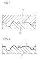
- Fig. 1, 1 denotes a section of the top of the master form as a partial cross-sectional view.
- this archetype can have the shape of a cylinder, which is preferably made of aluminum. It has the upper side O, which is surface-structured, the surface structure being achieved by blasting, for example shot peening, so that the elevations 2 with the undercuts 2 'and the depressions 3 have been created.
- This structured surface is then electroplated with a chrome layer 4.
- the chrome layer 4 changes at the points 4 ', that is, in front of exposed points of the elevations 2, the topography of the surface, for example at 4 ⁇ , but more so that the undercuts increase.
- undercuts are the reason why the beam-roughened surface appears in many respects to be less favorable than, for example, a spherical cap topography. If the undercuts are removed, the beam-roughened surface has been found to be superior to all other surface structures, as was found.
- This chrome layer 4 is then covered with a bright nickel layer 5. This completely flattens the surface and in particular the flanks of the chrome-layered elevations / depressions, so that there are no longer any undercuts / undercuts, be it the undercuts from the blasting treatment or those from the galvanic application of the chrome layer 4.
- the leveling electroplating layer 5 (bright nickel layer ) generated top of the original form 1 is now used for the galvanoplastic impression of the Metal foil 7 according to FIG. 2.
- Its material preferably consists of nickel. Your side coming into contact with the arch has the negative profile of the structural profile generated by blasting, but without any overhangs on the flanks 8 of its elevations 9, which not only optimizes them in terms of printing function, but also improves them in terms of cleaning technology and avoids nests for long-term corrosion .
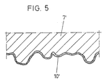
- This metal foil 7 can be directly the metal foil according to the invention or the negative form N for producing a metal foil 7 ', shown in Fig. 3.
- Both the metal foil 7 and 7' are always material-homogeneous duplicates of the corresponding original mold surface, whereby for the positive version according to 7 ', it is very important that the differently high contact surfaces (mountain peaks) are provided relatively widely and can be influenced with regard to their position and formation, the factors of material homogeneity and the lack of any undercuts to these together contribute to the optimization of use.
- the metal foil 7 can still be coated with a thin chrome layer 10 after the electroplating, which not only optimizes the stability but also the lubrication-preventing behavior.
- the metal foil 7 ' so in which the positive profile of the original form is equipped with this thin chrome layer 10'.
- the thickness of the chrome layer 4 is preferably 40-50 mü, that of the bright nickel layer at 10-15 mü.
Landscapes
- Printing Plates And Materials Therefor (AREA)
- Electroplating Methods And Accessories (AREA)
- Laminated Bodies (AREA)
- Laser Beam Processing (AREA)
- Supply, Installation And Extraction Of Printed Sheets Or Plates (AREA)
- Rotary Presses (AREA)
- Electroplating And Plating Baths Therefor (AREA)
- Adhesives Or Adhesive Processes (AREA)
- Breeding Of Plants And Reproduction By Means Of Culturing (AREA)
- Manufacture Or Reproduction Of Printing Formes (AREA)
- Moulds For Moulding Plastics Or The Like (AREA)
- Treatments Of Macromolecular Shaped Articles (AREA)
Abstract
Description
- Die Erfindung betrifft eine von einer Urform im Wege der galvanoplastischen Abformung hergestellte Metallfolie als Aufzug für bogenführende Zylinder und/oder Trommeln von Rotationsdruckmaschinen, deren eine Fläche glatt und deren gegenüberliegende Fläche oberflächenstrukturiert ist.
- Die bekannten Metallfolien dieser Art (DE-AS 26 05 330) bestehen vorzugsweise aus massivem Nickel und besitzen eine Oberflächenstruktur, die im wesentlichen dem für gleiche Zwecke ebenfalls vorbekannten Glasperlentuch entspricht. Dies resultiert daraus, daß die galvanoplastische Abformung der Metallfolien von einer Negativform erfolgt, die ihrerseits von einer positivform Urform abgeformt ist, welche aus einer Trägerfolie mit aufgebrachter Gummischicht besteht, in die teilweise aus der Oberfläche herausragend Glaskugeln eingebettet sind. Vorteilhaft an diesen Metallfolien ist die Tatsache, daß die Oberflächenstruktur weitgehend reproduzierbar ist. Das ist wichtig für den zügigen Einsatz im Druckbetrieb, beispielsweise für den kontrollfreien Austausch einer beschädigten Metallfolie gegen eine neue. Nachteilig an diesen Metallfolien ist jedoch, daß keine optimale Oberflächen-Topographie im Hinblick auf verschiedene Arbeitsanforderungen vorliegt.
- Die gleichen Nachteile treten bei einer anderen vorbekannten Lösung auf (EP-PS 17 776), bei denen die bogenführende Folie als Aufzug für Gegendruckzylinder von Rotationsdruckmaschinen für Schön- und Widerdruck auf der einen Fläche glatt ausgebildet und auf der gegenüberliegenden Fläche mit statistisch gleichmäßig verteilten, gleich hohen Kugelkalotten versehen ist und bei welcher die Folie von einer Trägerschicht und einer Deckschicht gebildet wird, die Träger schicht aus Nickel oder Kunststoff mit hohem Elastizitätsmodul, z.B. Polyamid oder PVC, besteht, wobei auf die Kugelkalotten-Seite eine deren Mikrorauheit ausgleichende, dünne Chromschicht als Deckschicht aufgebracht ist. Der Ausgleich nur der Mikrorauheit verändert die beabsichtigte, sehr gleichmäßige Kugelkalotten-Topographie der Oberfläche nicht.
- Im Hinblick auf einen über die Rauhheit zu erreichenden Kompromiß schlägt die DE-PS 12 58 873 Oberflächenstrukturen eines Gegendruckzylinders bzw. einer diesem zuzuordnenden Aluminiumfolie vor, die als Chromoberfläche mit einer Rauhheit (RMS) zwischen 2 und 7,5 mü gestaltet ist. Dadurch sollten zwei Grenzbedingungen im Kompromiß optimal erfüllt werden, nämlich, daß die Rauhheit einerseits genügend groß ist, um einen gewissen (dort behaupteten) Farb-Abstoßeffekt zu verwirklichen, beispielsweise um ein Schmieren des frisch bedruckten Bogens an seiner Rückseite beim Widerdruck zu verhindern, andererseits die Rauhheit aber auch so klein wie möglich sei, um den optimalen Traganteil für die Auflagefläche des Bogens sicherzustellen. Einerseits wird dieser Kompromiß, wie gefunden wurde, nicht optimal erreicht. Andererseits ist an dieser Lösung nachteilig, daß sie hinsichtlich der Oberflächenstruktur nicht reproduzierbar ist. Selbst wenn man die Bemessung der Rauhheit (im entsprechenden Mittel über die gesamte Folie betrachtet) mit vertretbarer Toleranz reproduziert, so weicht die Oberflächenstruktur insgesamt jeder Folie wieder sehr erheblich von der anderen Folie bzw. jede Zylinderoberfläche von der nächsten Zylinderoberfläche ab. Auch ist die reproduzierbare Strahlbehandlung solcher dünnen Aluminiumfolien problematisch, ferner deren Benutzungsstabilität. Alle diesbezüglich vorbekannten Produkte mit strahlgerauhter Oberfläche stellen demgemäß Unikate dar.
- Aufgabe der vorliegenden Erfindung ist es, eine gattungsgemäße Metallfolie so auszugestalten, daß bei optimaler Anpassung der Oberflächenstruktur an die Funktionsbedingungen der Folie eine stets identische Reproduzierbarkeit derselben gegeben ist.
- Erreicht ist dies gemäß der Erfindung entweder dadurch, daß die Oberflächenstruktur der Metallfolie einer durch Strahlbehandlung gerauhten und zur Eliminierung von Hinterschnitten mit einer einebnenden Galvano-Schicht, z.B. Glanznickelschicht, überzogenen Oberseite der Urform entspricht oder dadurch, daß die Metallfolie von der durch Strahlbehandlung gerauhten und zur Eliminierung von Hinterschnitten mit einer einebnenden Galvano-Schicht z. B. einer Glanznickelschicht, überzogenen Oberseite der Urform abgeformt ist.
- Zufolge dieser Ausgestaltung ist eine Metallfolie als Aufzug für bogenführende Zylinder und/oder Trommeln von Rotationsdruckmaschinen gegeben, deren Oberflächenstruktur grundsätzlich das Duplikat einer durch Strahlrauhung erzeugten (und danach von Hinterschnitten befreiten) Oberfläche darstellt, und dadurch einerseits jederzeit eindeutig höchstgradig genau reproduzierbar ist und andererseits optimale Bedingungen bezüglich einer Abschmierverhinderung bringt. Diesbezüglich wurde gefunden, daß die Struktur einer strahlgerauhten und entsprechend eingeebneten Fläche sowohl direkt (als Positiv-Profil) wie auch mit deren Negativ-Profil den günstigsten Kompromiss bietet, insbesondere hinsichtlich Traganteil, Waschbarkeit der Metallfolie und der Abschmierverhinderung. Alles zusammen bringt optimale Benutzungsbedingungen. Dabei ist das Wesentliche der Erfindung die Erkenntnis, daß man diese Optimierung erreicht, wenn man die durch Strahlbehandlung erzeugten Rauhigkeiterhebungen einer Oberfläche (der Urform) einebnet und dabei von allen etwaigen Hinterschnitten befreit, so daß also die abgeformte fertige Metallfolie keine Vertiefungen besitzen kann, die sich zur Tiefe hin erweitern bzw. keine Erhöhungen mit einem Überhang. Die Strahlbehandlung zur Rauhung der Oberseite der Urform kann durch bekannte Blas- oder Strahl-Verfahren erfolgen, z.B. durch Kugelstrahlen. Die diesbezüglich erzeugte Oberfläche kann zusätzlich - auch zur Stabilisierung und Verlängerung der Lebensdauer- mit einer Chromschicht ausgestattet sein. Eine solche Chromschicht, aufgebracht auf eine durch Strahlung erzeugte und dann galvanisch eingeebnete Oberflächen-Topographie, verbessert den Oberflächenausgleich noch weiter, weil z.B. wegen der fehlenden Hinterschneidungen keine elektrolytisch bevorzugten Kanten/Spitzen etc. vorliegen. Die entsprechende Metallfolie kann auch als Bespannung für den Druckzylinder einer Rotationsdruckmaschine eingesetzt werden. Dabei sind die Kuppen bestens geeignet, den Reibwert der Zylinderoberfläche zu erhöhen, so daß die Papierzugkräfte für die Greifer geringer bemessen sein können; ein Herausziehen des Bogens aus den Greifern ist dann trotzdem verhindert. Die Ausbildung der Kuppeln (spitz oder flach, hoher oder geringer Traganteil) kann dem jeweiligen Anwendungsfall (erster Umführzylinder, dritter Umführzylinder, Druckzylinder, Auslagetrommel oder dergleichen) angepaßt werden. Trotz relativ dünner Struktur ergibt sich eine sehr haltbare Bauform. Die bogenberührende Oberfläche ist auch reinigungsoptimal. Die eingeebneten Flanken der Erhöhungen vermeiden Nester zur Farbansammlung bzw. Resten eines etwaigen Reinigungsmittels. Über das jeweilige Strahlverfahren zur Rauhung der Oberseite der Urform kann eine wesentlich weitergehende Anpassung an den späteren Einsatzzweck der Metallfolie erreicht werden, als dies bei den bis dahin in Kugelkalotten-Struktur galvanisch abgeformten Metallfolien möglich war. Wegen der optimalen Traganteile, die eine solche Toprgraphie mit sich bringt, ist eine solche Metallfolie auch bestens geeignet, um auf einem Zylinder durch Unterlegen der Folie eine sehr feine Anpassung an unterschiedliche Papierstärken vorzunehmen. Es ergibt sich, wie gefunden wurde, wegen der speziellen Bedingungen bezüglich Traganteil der Fläche, Tragflächengestalt, Material, Verteilung der Traganteile, Höhendifferenz und deren Verteilung, Gestalt der Kuppen und Tälern, insbesondere deren Flanken, eine Lösung, die einsatztechnisch sowohl den mikrogeglätteten, gleichhohen und gleichmäßig verteilten Kugelkalotten überlegen ist als auch den strahlgerauhten (plus verchromten) Zylinderflächen (mit Hinterschneidungs-Nestern). Durch die Bemessung der aufzubringenden Glanznickel-Masse ergibt sich dabei noch eine gute Möglichkeit, die obigen Faktoren zu beeinflussen.
- Der Gegenstand der Erfindung ist auf der beiliegenden Zeichnung in zwei Ausführungsbeispielen skizzenmäßig dargestellt.
- In Fig. 1 bezeichnet 1 einen Ausschnitt aus der Oberseite der Urform als Teilquerschnittsdarstellung. Diese Urform kann insgesamt die Form eines Zylinders besitzen, der vorzugsweise aus Aluminium besteht. Er weist die Oberseite O auf, welche oberflächenstrukturiert ist, wobei die Oberflächenstruktur durch Strahlbehandlung, z.B. Kugelstrahlen erzielt ist, so daß die Erhebungen 2 mit den Hinterschneidungen 2′ und die Vertiefungen 3 entstanden sind. Diese strukturierte Oberfläche wird anschließend galvanisch mit einer Chromschicht 4 überzogen. Wie erkennbar, verändert die Chromschicht 4 an den Stellen 4′, also vor exponierten Punkten der Erhöhungen 2 die Topographie der Oberfläche, z.B. bei 4˝, jedoch mehr so, daß die Hinterschneidungen sich vergrößern. Es ist ein wesentliches Element der Erfindung, erkannt zu haben, daß solche Hinterschneidungen die Ursache dafür sind, daß die strahlgerauhte Oberfläche in vieler Hinsicht ungünstiger erscheint als z.B. eine Kugelkalotten-Topographie. Beseitigt man die Hinterschneidungen, erweist sich - wie gefunden wurde - die strahlgerauhte Fläche allen anderen Oberfläche-Strukturen gegenüber überlegen. Diese Chromschicht 4 wird anschließend mit einer Glanznickelschicht 5 überdeckt. Diese ebnet die Oberfläche und insbesondere die Flanken der chromschichtüberdeckten Erhebungen/Vertiefungen völlig ein, so daß keinerlei Hinterschnitte/Hinterschneidungen mehr auftreten, seien es die Hinterschneidungen aus der Strahlbehandlung oder solche aus dem galvanischen Aufbringen der Chromschicht 4. Diese durch die einebnende Galvanoschicht 5 (Glanznickelschicht) erzeugte Oberseite der Urform 1 wird nun benutzt zur galvanoplastischen Abformung der Metallfolie 7 gemäß Fig. 2. Deren Material besteht vorzugsweise aus Nickel. Ihre mit dem Bogen in Berührung tretende Seite besitzt dabei das Negativ-Profil des durch Strahlbehandlung erzeugten Strukturprofiles, dies jedoch ohne jegliche Überhänge an den Flanken 8 ihrer Erhebungen 9, was sie nicht nur druckfunktionstechnisch optimiert, sondern auch reinigungstechnisch verbessert und Nester zur langfristigen Korrosion vermeidet. Diese Metallfolie 7 kann unmittelbar die erfindungsgemäße Metall-Folie sein oder die Negativ-Form N zur Herstellung einer Metallfolie 7′, dargestellt in Fig. 3. Sowohl bei der Metallfolie 7 wie 7′ handelt es sich stets um materialhomogene Duplikate der entsprechenden Urformoberfläche, wobei für die Positiv-Version gemäß 7′ sehr wichtig ist, daß die unterschiedlich hohen Auflageflächen (Bergspitzen) relativ weit verstreut vorgesehen und hinsichtlich ihrer Lage und Ausbildung beeinflußbar sind, wobei die Faktoren der Materialhomogenität und das Fehlen jegliche Hinterschneidungen an diesen gemeinsam zur Benutzungsoptimierung beitragen.
- Wie aus Fig. 4 ersichtlich, kann die Metallfolie 7 nach der galvanischen Abformung noch mit einer dünnen Chromschicht 10 überzogen sein, was nicht nur die Stabilität, sondern auch das abschmierverhindernde Verhalten optimiert. Das gleiche gilt, wie in Fig. 5 dargestellt, für die Metallfolie 7′, bei der also das Positiv-Profil der Urform mit dieser dünnen Chromschicht 10′ ausgestattet ist.
- Jedesmal liegt eine Rauhigkeitsstruktur vor, bei welcher die Oberflächenstruktur einschließlich der Flanken der durch Strahlbehandlung erzeugten Rauhigkeitserhebungen eingeebnet ist. Die Rauhigkeit liegt bei 30 - 60 Rz; der Traganteil TP ist in den einzelnen Tiefen:
TP bei Tiefe von 10.0 mü = 15 %
TP bei Tiefe von 20.0 mü = 50 %
TP bei Tiefe von 30.0 mü = 84 % - Die Dicke der Chromschicht 4 liegt vorzugsweise bei 40-50 mü, diejenige der Glanznickelschicht bei 10-15 mü. Die Dicke der Chromschicht 10 bzw. 10′ liegt bei 10 mü.
- Alle in der Beschreibung erwähnten und in der Zeichnung dargestellten neuen Merkmale sind erfindungswesentlich, auch soweit sie in den Ansprüchen nicht ausdrücklich beansprucht sind.
Claims (5)
dadurch gekennzeichnet,
daß die Oberflächenstruktur der Metallfolie (7) einer durch Strahlbehandlung gerauhten und zur Eliminierung von Hinterschnitten (2′) mit einer einebnenden Galvano-Schicht (5) z. B. einer Glanznickelschicht, überzogenen Oberseite (O) der Urform (1) entspricht.
dadurch gekennzeichnung,
daß die Metallfolie (7) von einer durch Strahlbehandlung gerauhten und zur Eliminierung von Hinterschnitten (2′) mit einer einebnenden Galvano-Schicht (5) z. B. einer Glanznikkelschicht, überzogenen Oberseite (O) der Urform (1) abgeformt ist.
dadurch gekennzeichnet,
daß die strukturierte Fläche der aus Nickel bestehenden Metallfolie (7) nach dem Abformen mit einer dünnen Chromschicht (10) überzogen ist.
dadurch gekennzeichnet,
daß die für die galvanoplastische Abformung vorgesehene Fläche der positiven Urform (1) unter Einsatz eines Blas- bzw. Strahlverfahrens aufgerauht ist und die aufgerauhte Fläche (bzw. aufgerauhte und dann verchromte Fläche) mit einer einebnenden galvanischen Schicht (5) überzogen ist.
Applications Claiming Priority (3)
| Application Number | Priority Date | Filing Date | Title |
|---|---|---|---|
| DE3905679 | 1989-02-24 | ||
| DE3905679A DE3905679A1 (de) | 1989-02-24 | 1989-02-24 | Metallfolie als aufzug fuer bogenfuehrende zylinder und/oder trommeln an rotationsdruckmaschinen |
| SG160394A SG160394G (en) | 1989-02-24 | 1994-11-04 | Positive original template for galvanoplastic shape of metallic foils |
Publications (3)
| Publication Number | Publication Date |
|---|---|
| EP0384146A2 true EP0384146A2 (de) | 1990-08-29 |
| EP0384146A3 EP0384146A3 (de) | 1991-07-10 |
| EP0384146B1 EP0384146B1 (de) | 1994-07-13 |
Family
ID=25878120
Family Applications (1)
| Application Number | Title | Priority Date | Filing Date |
|---|---|---|---|
| EP90101441A Expired - Lifetime EP0384146B1 (de) | 1989-02-24 | 1990-01-25 | Positive Urform zur galvanoplastischen Abformung von Metallfolien |
Country Status (10)
| Country | Link |
|---|---|
| US (1) | US5102744A (de) |
| EP (1) | EP0384146B1 (de) |
| JP (1) | JPH0794193B2 (de) |
| AT (1) | ATE108374T1 (de) |
| AU (1) | AU626978B2 (de) |
| CA (1) | CA2008575A1 (de) |
| DE (2) | DE3905679A1 (de) |
| ES (1) | ES2058615T3 (de) |
| HK (1) | HK21195A (de) |
| SG (1) | SG160394G (de) |
Cited By (1)
| Publication number | Priority date | Publication date | Assignee | Title |
|---|---|---|---|---|
| EP1040921A1 (de) * | 1999-03-27 | 2000-10-04 | Koenig & Bauer Aktiengesellschaft | Oberfläche für Maschinenteile in Druckmaschinen |
Families Citing this family (7)
| Publication number | Priority date | Publication date | Assignee | Title |
|---|---|---|---|---|
| DE19515394C1 (de) * | 1995-04-26 | 1996-05-23 | Roland Man Druckmasch | Verfahren zur Herstellung einer Oberflächenstruktur und dessen Anwendung, vorzugsweise für einen Druckmaschinenzylinder |
| AU2001296868A1 (en) | 2000-09-11 | 2002-03-26 | Allison Advanced Development Company | Mechanically grooved sheet and method of manufacture |
| US6811863B2 (en) | 2001-07-20 | 2004-11-02 | Brite Ideas, Inc. | Anti-marking coverings for printing presses |
| CA2651816C (en) | 2006-05-12 | 2016-02-02 | Printguard, Inc. | Fixture for anti-marking coverings for printing presses |
| ATE473870T1 (de) * | 2006-07-17 | 2010-07-15 | Heidelberger Druckmasch Ag | Verfahren zum herstellen einer strukturierten, drucktechnischen oberfläche |
| US20090277677A1 (en) * | 2008-05-12 | 2009-11-12 | Occam Portfolio Llc | Electronic Assemblies without Solder and Method for their Design, Prototyping, and Manufacture |
| US8462391B2 (en) * | 2009-03-13 | 2013-06-11 | Heidelberger Druckmaschinen Ag | Method for producing a pseudo-stochastic master surface, master surface, method for producing a cylinder cover, cylinder cover, machine processing printing material, method for producing printed products and method for microstamping printing products |
Family Cites Families (23)
| Publication number | Priority date | Publication date | Assignee | Title |
|---|---|---|---|---|
| US1789273A (en) * | 1929-11-04 | 1931-01-13 | Stanley Works | Process of ornamenting strip metal |
| US2020177A (en) * | 1933-11-03 | 1935-11-05 | Leo E Grove | Method of manufacturing slip sheets |
| DE639956C (de) * | 1934-08-28 | 1936-12-16 | Original Checko G M B H | Einlegeblatt fuer Schreibmaschinen u. dgl. zum Erzielen nicht radierbarer Schrift |
| FR956760A (de) * | 1943-04-19 | 1950-02-07 | ||
| US2991544A (en) * | 1957-05-07 | 1961-07-11 | American Can Co | Bright surfaced metal sheets and method of producing same |
| US3161130A (en) * | 1963-05-27 | 1964-12-15 | Miller Printing Machinery Co | Printing apparatus |
| US3398442A (en) * | 1965-03-04 | 1968-08-27 | Gar Prec Products Inc | Metal abrasive sheet and a method of making same |
| US3556874A (en) * | 1967-08-01 | 1971-01-19 | Republic Steel Corp | Metal articles with controlled finish |
| US3649474A (en) * | 1969-12-05 | 1972-03-14 | Johns Manville | Electroforming process |
| CH591570A5 (de) * | 1972-11-28 | 1977-09-30 | Buser Ag Maschf Fritz | |
| DE2446188C3 (de) * | 1974-09-27 | 1983-11-24 | Heidelberger Druckmaschinen Ag, 6900 Heidelberg | Bogenführende Mantelfläche von Gegendruckzylindern oder Bogenüberführungszylindern in Rotationsoffsetdruckmaschinen |
| CH578940A5 (de) * | 1975-02-14 | 1976-08-31 | Von Roll Ag | |
| US4088544A (en) * | 1976-04-19 | 1978-05-09 | Hutkin Irving J | Composite and method for making thin copper foil |
| CH620863A5 (en) * | 1977-06-24 | 1980-12-31 | Von Roll Ag | Metal foil with sheet-bearing surface |
| DD136480A1 (de) * | 1978-05-26 | 1979-07-11 | Herbert Patzelt | Ein-oder mehrschichtiger mantel fuer bogenfuehrende zylinder |
| DE2916505A1 (de) * | 1979-04-24 | 1980-10-30 | Heidelberger Druckmasch Ag | Bogenfuehrende folie als aufzug fuer gegendruckzylinder |
| EP0036316B1 (de) * | 1980-03-17 | 1986-03-05 | Nippon Paint Co., Ltd. | Lithographische Druckplatte |
| GB2081178A (en) * | 1980-07-29 | 1982-02-17 | Heidelberger Druckmasch Ag | Sheet-guiding Foil as a Dressing for Back Pressure Cylinders |
| JPS5825592A (ja) * | 1981-08-06 | 1983-02-15 | Masao Umehara | 重力による落下の衝撃力を取り出す装置 |
| US4735883A (en) * | 1985-04-06 | 1988-04-05 | Canon Kabushiki Kaisha | Surface treated metal member, preparation method thereof and photoconductive member by use thereof |
| DE3537483C1 (de) * | 1985-10-22 | 1986-12-04 | Kernforschungszentrum Karlsruhe Gmbh, 7500 Karlsruhe | Verfahren zum Herstellen einer Vielzahl plattenfoermiger Mikrostrukturkoerper aus Metall |
| US4775599A (en) * | 1985-12-24 | 1988-10-04 | Kawasaki Steel Corporation | Cold rolled steel sheets having an improved press formability |
| DE3815977A1 (de) * | 1988-05-10 | 1989-11-30 | Mtu Muenchen Gmbh | Folienzwischenlage zur fuegung von reibkorrosionsgefaehrdeten maschinenbauteilen |
-
1989
- 1989-02-24 DE DE3905679A patent/DE3905679A1/de active Granted
-
1990
- 1990-01-24 AU AU48798/90A patent/AU626978B2/en not_active Ceased
- 1990-01-25 CA CA002008575A patent/CA2008575A1/en not_active Abandoned
- 1990-01-25 EP EP90101441A patent/EP0384146B1/de not_active Expired - Lifetime
- 1990-01-25 ES ES90101441T patent/ES2058615T3/es not_active Expired - Lifetime
- 1990-01-25 AT AT90101441T patent/ATE108374T1/de active
- 1990-01-25 DE DE59006386T patent/DE59006386D1/de not_active Expired - Fee Related
- 1990-02-26 JP JP2042731A patent/JPH0794193B2/ja not_active Expired - Fee Related
- 1990-02-26 US US07/485,242 patent/US5102744A/en not_active Expired - Lifetime
-
1994
- 1994-11-04 SG SG160394A patent/SG160394G/en unknown
-
1995
- 1995-02-16 HK HK21195A patent/HK21195A/xx not_active IP Right Cessation
Cited By (1)
| Publication number | Priority date | Publication date | Assignee | Title |
|---|---|---|---|---|
| EP1040921A1 (de) * | 1999-03-27 | 2000-10-04 | Koenig & Bauer Aktiengesellschaft | Oberfläche für Maschinenteile in Druckmaschinen |
Also Published As
| Publication number | Publication date |
|---|---|
| HK21195A (en) | 1995-02-24 |
| ES2058615T3 (es) | 1994-11-01 |
| EP0384146B1 (de) | 1994-07-13 |
| AU626978B2 (en) | 1992-08-13 |
| SG160394G (en) | 1995-03-17 |
| DE3905679A1 (de) | 1990-08-30 |
| DE59006386D1 (de) | 1994-08-18 |
| US5102744A (en) | 1992-04-07 |
| AU4879890A (en) | 1990-08-30 |
| DE3905679C2 (de) | 1992-07-02 |
| CA2008575A1 (en) | 1990-08-24 |
| JPH0794193B2 (ja) | 1995-10-11 |
| EP0384146A3 (de) | 1991-07-10 |
| JPH02276689A (ja) | 1990-11-13 |
| ATE108374T1 (de) | 1994-07-15 |
Similar Documents
| Publication | Publication Date | Title |
|---|---|---|
| EP0017776B1 (de) | Bogenführende Folie als Aufzug für Gegendruckzylinder | |
| DE2446188C3 (de) | Bogenführende Mantelfläche von Gegendruckzylindern oder Bogenüberführungszylindern in Rotationsoffsetdruckmaschinen | |
| EP0739719B1 (de) | Bedruckstofführende Oberflächenstruktur, vorzugsweise für Druckmaschinenzylinder oder deren Aufzüge | |
| DE3931479A1 (de) | Bogenfuehrende folie als aufzug fuer gegendruckzylinder und bogenueberfuehrungszylinder in bogenoffsetdruckmaschinen fuer schoen- und widerdruck | |
| DE3045322C2 (de) | Verfahren zum Herstellen einer Tiefdruckform | |
| EP1216832A1 (de) | Zylindermantelprofil | |
| DE3110842A1 (de) | Rakel fuer den tiefdruck mit kunststoff-druckschichten | |
| EP0384146B1 (de) | Positive Urform zur galvanoplastischen Abformung von Metallfolien | |
| EP0588091B1 (de) | Folie als Aufzug für einen Gegendruckzylinder einer Offset-Bogen-Rotationsdruckmaschine zum Schön- und Widerdruck | |
| DE2624930C3 (de) | Raster für den Rotations-Tiefdruck | |
| DE69703313T2 (de) | Oberfläche für die Beförderung eines flüssigen, mehr oder weniger viscosen Produkts auf eine Unterlage, Herstellungsverfahren dieser Oberfläche und aus dieser Oberfläche gebildetes Drucktuch für Offset-Druckverfahren | |
| DE202007006656U1 (de) | Tampondruckmaschine und Tampon dafür | |
| DE2050663C3 (de) | Druckzylinder für eine Stahlstichdruckmaschine und Verfahren zu dessen Herstellung | |
| DE102008019254B4 (de) | Bedruckstoff kontaktierende Fläche mit einer Oberflächenstrukturierung | |
| EP0402377A1 (de) | Verfahren zur herstellung eines mit einem prägemuster versehenen metallischen endlosbandes. | |
| DE2605330A1 (de) | Verfahren zur herstellung von bogenfuehrenden folien fuer druckmaschinen | |
| DE3138164A1 (de) | Verfahren zur herstellung eines mehrfarbigen plattenandruckes fuer fussbodendessinandrucke, dekordrucke und dgl. | |
| DE3913818C2 (de) | ||
| DE8816141U1 (de) | Mehrschichtiges Drucktuch | |
| DE7911947U1 (de) | Bogenfuehrende folie als aufzug fuer gegendruckzylinder | |
| DE8911255U1 (de) | Bogenführende Folie als Aufzug für Gegendruckzylinder und Bogenüberführungszylinder in Bogenoffsetdruckmaschinen für Schön- und Widerdruck | |
| EP1880860B1 (de) | Verfahren zum Herstellen einer strukturierten, drucktechnischen Oberfläche | |
| DE1293174B (de) | Verfahren zum Herstellen eines Summentypentraegers | |
| DE102021004568A1 (de) | Tiefdruckform für die Herstellung von Druckerzeugnissen im Tiefdruck, Vorlage und Herstellungsverfahren für eine Tiefdruckform | |
| DE10039912A1 (de) | Aufzug für einen Gegendruckzylinder |
Legal Events
| Date | Code | Title | Description |
|---|---|---|---|
| PUAI | Public reference made under article 153(3) epc to a published international application that has entered the european phase |
Free format text: ORIGINAL CODE: 0009012 |
|
| 17P | Request for examination filed |
Effective date: 19900125 |
|
| AK | Designated contracting states |
Kind code of ref document: A2 Designated state(s): AT CH DE ES FR GB IT LI NL SE |
|
| PUAL | Search report despatched |
Free format text: ORIGINAL CODE: 0009013 |
|
| AK | Designated contracting states |
Kind code of ref document: A3 Designated state(s): AT CH DE ES FR GB IT LI NL SE |
|
| 17Q | First examination report despatched |
Effective date: 19930618 |
|
| GRAA | (expected) grant |
Free format text: ORIGINAL CODE: 0009210 |
|
| AK | Designated contracting states |
Kind code of ref document: B1 Designated state(s): AT CH DE ES FR GB IT LI NL SE |
|
| REF | Corresponds to: |
Ref document number: 108374 Country of ref document: AT Date of ref document: 19940715 Kind code of ref document: T |
|
| REF | Corresponds to: |
Ref document number: 59006386 Country of ref document: DE Date of ref document: 19940818 |
|
| ITF | It: translation for a ep patent filed | ||
| GBT | Gb: translation of ep patent filed (gb section 77(6)(a)/1977) |
Effective date: 19940919 |
|
| REG | Reference to a national code |
Ref country code: ES Ref legal event code: FG2A Ref document number: 2058615 Country of ref document: ES Kind code of ref document: T3 |
|
| ET | Fr: translation filed | ||
| EAL | Se: european patent in force in sweden |
Ref document number: 90101441.5 |
|
| PLBE | No opposition filed within time limit |
Free format text: ORIGINAL CODE: 0009261 |
|
| STAA | Information on the status of an ep patent application or granted ep patent |
Free format text: STATUS: NO OPPOSITION FILED WITHIN TIME LIMIT |
|
| 26N | No opposition filed | ||
| PGFP | Annual fee paid to national office [announced via postgrant information from national office to epo] |
Ref country code: AT Payment date: 19960111 Year of fee payment: 7 |
|
| PGFP | Annual fee paid to national office [announced via postgrant information from national office to epo] |
Ref country code: SE Payment date: 19960115 Year of fee payment: 7 |
|
| PGFP | Annual fee paid to national office [announced via postgrant information from national office to epo] |
Ref country code: NL Payment date: 19960123 Year of fee payment: 7 |
|
| PGFP | Annual fee paid to national office [announced via postgrant information from national office to epo] |
Ref country code: ES Payment date: 19960124 Year of fee payment: 7 |
|
| PG25 | Lapsed in a contracting state [announced via postgrant information from national office to epo] |
Ref country code: AT Effective date: 19970125 |
|
| PG25 | Lapsed in a contracting state [announced via postgrant information from national office to epo] |
Ref country code: SE Effective date: 19970126 |
|
| PG25 | Lapsed in a contracting state [announced via postgrant information from national office to epo] |
Ref country code: ES Free format text: LAPSE BECAUSE OF NON-PAYMENT OF DUE FEES Effective date: 19970127 |
|
| PG25 | Lapsed in a contracting state [announced via postgrant information from national office to epo] |
Ref country code: NL Effective date: 19970801 |
|
| NLV4 | Nl: lapsed or anulled due to non-payment of the annual fee |
Effective date: 19970801 |
|
| EUG | Se: european patent has lapsed |
Ref document number: 90101441.5 |
|
| REG | Reference to a national code |
Ref country code: ES Ref legal event code: FD2A Effective date: 19990201 |
|
| REG | Reference to a national code |
Ref country code: GB Ref legal event code: IF02 |
|
| PGFP | Annual fee paid to national office [announced via postgrant information from national office to epo] |
Ref country code: GB Payment date: 20061218 Year of fee payment: 18 |
|
| PGFP | Annual fee paid to national office [announced via postgrant information from national office to epo] |
Ref country code: CH Payment date: 20070104 Year of fee payment: 18 |
|
| PGFP | Annual fee paid to national office [announced via postgrant information from national office to epo] |
Ref country code: FR Payment date: 20061227 Year of fee payment: 18 |
|
| PGFP | Annual fee paid to national office [announced via postgrant information from national office to epo] |
Ref country code: DE Payment date: 20080218 Year of fee payment: 19 Ref country code: IT Payment date: 20080123 Year of fee payment: 19 |
|
| REG | Reference to a national code |
Ref country code: CH Ref legal event code: PL |
|
| GBPC | Gb: european patent ceased through non-payment of renewal fee |
Effective date: 20080125 |
|
| PG25 | Lapsed in a contracting state [announced via postgrant information from national office to epo] |
Ref country code: CH Free format text: LAPSE BECAUSE OF NON-PAYMENT OF DUE FEES Effective date: 20080131 Ref country code: LI Free format text: LAPSE BECAUSE OF NON-PAYMENT OF DUE FEES Effective date: 20080131 |
|
| REG | Reference to a national code |
Ref country code: FR Ref legal event code: ST Effective date: 20081029 |
|
| PG25 | Lapsed in a contracting state [announced via postgrant information from national office to epo] |
Ref country code: GB Free format text: LAPSE BECAUSE OF NON-PAYMENT OF DUE FEES Effective date: 20080125 |
|
| PG25 | Lapsed in a contracting state [announced via postgrant information from national office to epo] |
Ref country code: FR Free format text: LAPSE BECAUSE OF NON-PAYMENT OF DUE FEES Effective date: 20080131 |
|
| PG25 | Lapsed in a contracting state [announced via postgrant information from national office to epo] |
Ref country code: DE Free format text: LAPSE BECAUSE OF NON-PAYMENT OF DUE FEES Effective date: 20090801 |
|
| PG25 | Lapsed in a contracting state [announced via postgrant information from national office to epo] |
Ref country code: IT Free format text: LAPSE BECAUSE OF NON-PAYMENT OF DUE FEES Effective date: 20090125 |