EP0383771B1 - Vorrichtung zum abstützen eines rahmens - Google Patents
Vorrichtung zum abstützen eines rahmens Download PDFInfo
- Publication number
- EP0383771B1 EP0383771B1 EP88907070A EP88907070A EP0383771B1 EP 0383771 B1 EP0383771 B1 EP 0383771B1 EP 88907070 A EP88907070 A EP 88907070A EP 88907070 A EP88907070 A EP 88907070A EP 0383771 B1 EP0383771 B1 EP 0383771B1
- Authority
- EP
- European Patent Office
- Prior art keywords
- frame
- legs
- wall
- horizontally extending
- jamb
- Prior art date
- Legal status (The legal status is an assumption and is not a legal conclusion. Google has not performed a legal analysis and makes no representation as to the accuracy of the status listed.)
- Expired - Lifetime
Links
- 238000005187 foaming Methods 0.000 claims description 7
- 208000007101 Muscle Cramp Diseases 0.000 claims 1
- 230000000903 blocking effect Effects 0.000 claims 1
- 230000000717 retained effect Effects 0.000 abstract 1
- 238000002788 crimping Methods 0.000 description 2
- 239000006260 foam Substances 0.000 description 2
- 238000009434 installation Methods 0.000 description 2
- 238000000034 method Methods 0.000 description 2
- 229910000831 Steel Inorganic materials 0.000 description 1
- 238000005452 bending Methods 0.000 description 1
- 230000006735 deficit Effects 0.000 description 1
- 238000005516 engineering process Methods 0.000 description 1
- 125000006850 spacer group Chemical group 0.000 description 1
- 239000010959 steel Substances 0.000 description 1
Images
Classifications
-
- E—FIXED CONSTRUCTIONS
- E06—DOORS, WINDOWS, SHUTTERS, OR ROLLER BLINDS IN GENERAL; LADDERS
- E06B—FIXED OR MOVABLE CLOSURES FOR OPENINGS IN BUILDINGS, VEHICLES, FENCES OR LIKE ENCLOSURES IN GENERAL, e.g. DOORS, WINDOWS, BLINDS, GATES
- E06B1/00—Border constructions of openings in walls, floors, or ceilings; Frames to be rigidly mounted in such openings
- E06B1/56—Fastening frames to the border of openings or to similar contiguous frames
- E06B1/58—Fastening frames to the border of openings or to similar contiguous frames by filling up the joints, e.g. by cementing
Definitions
- the invention relates to a device for supporting a frame, such as a door frame, which is inserted and adjusted in, for example, a recess in a wall and which can be fastened by partially foaming the space between the frame and the recess.
- the door frame in order to enclose door frames or the like in wall openings, can be aligned in the wall opening by means of wooden wedges to be fitted in the space between the wall and frame before foaming.
- This technique has the disadvantage that a message of the frame can cause the wedges to slip, so that a new adjustment is required.
- These disadvantages have been eliminated by the measures described in the international publication WO 85/02648.
- the frames to be inserted into a wall opening are aligned by means of a controlled pressure in the upper corner areas of the frame. Air-filled pillows can be used for this. So that there is no uncontrolled bending of the longitudinal legs like reveal parts when foaming, adjustable spreading elements run between them, which can be produced by telescopically displaceable plastic pipes.
- DE-A-32 19 066 shows an assembly auxiliary frame for frames, for example.
- the subframe comprises two vertically running rails, from which telescopically adjustable cross supports extend.
- Cross supports and rails form one unit and are therefore bulky.
- Jibs also extend from the rails, which on the one hand comprise sections of the frame reveal and on the other act with the change of masonry. Since the brackets are rigidly connected to the longitudinal rails, the soffits cannot be fixed if the space between the frame and the wall opening is small. In this case, safe installation is not guaranteed.
- a mounting bracket for frames is described in DE-A-27 04 692.
- the side reveal parts are gripped by screw devices, from which wing screws emanate, which interact with walls in such a way that the frame is positioned to the desired extent.
- screw devices from which wing screws emanate, which interact with walls in such a way that the frame is positioned to the desired extent.
- the frame is made of flat steel and has a clothing width.
- the object of the present invention is to design a device of the type mentioned in such a way that without complex measures or wedges and without special design features of the frame it is ensured that even after the positioning of the frame, there is no unwanted slipping and tipping out without the wall opening Reworking itself is required to set the frame.
- the device is a fastening element which can be clamped at a desired location and clamps the upper horizontally extending frame leg, from which projects an element which is supported on the wall and is formed integrally with and immovably to the device.
- the element is a rod-shaped section of the fastening element and preferably has a spherical free end.
- the element has two vertically on the bottom and top extending frame legs on adjacent legs, which are connected via a locking element.
- the legs themselves preferably work together like a mouth.
- the surfaces of the legs that bear against the sides of the frame leg are designed to be shock-absorbing and preferably also slip-resistant.
- the teaching according to the invention ensures that a frame inserted in a wall joint cannot slip in an uncontrolled manner in the direction of the side on which another element such as a wing is hung on the frame.
- a device which essentially consists of a clamping element which grips the frame and an element which projects from it and which is supported on the wall opening like a lintel.
- a screw clamp can be used which grips the frame, to have an element protrude from the upper leg in the direction of the fall.
- a tubular element extends from one, preferably the movable leg, the free end of which, as mentioned, is preferably spherical in order to ensure a secure fit on the masonry.
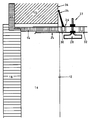
- the single figure shows a sectional view through a wall opening with an inserted door frame.
- the frame (12) is arranged below the lintel (10), one of which has the horizontally extending leg (14) and a reveal (16) is recognizable.
- a door (18) is hung on the frame (12) via hinges (not shown).
- the door frame (12) can be aligned according to the method or the elements in the wall opening, as have been described in detail in the international publication WO 85/02648. Of course, you can also fall back on the old technology, in which wedges are inserted between the reveal and the opening in the wall and cut strips between the reveal parts are clamped.
- a device (22) which counteracts this force.
- the device (22) has two clamping elements (24) and (26), which can be designed as legs or rods, as are known, for example, from screw clamps.
- the legs (24) and (26) are then penetrated by a screw element (28). So that the elements (24) and (26) can lie flat against the horizontal leg of the frame (12), there are preferably interchangeable spacer elements (30) and (32) between the clamping elements (24) and (26), preferably in front of and arranged behind the screw element (28).
- a limb (34) protrudes from the upper clamping element (26) facing the lintel (10) and bears on the outside (36) of the lintel (10) via a correctly installed device (22). If the device (22) is firmly connected to the leg (14) in this position, it is ensured that the door frame (12) can no longer slide to the left, even if the door (18) is attached to it. This ensures that the door frame (12) can be filled with foam in the masonry without slipping out of control. After the foam has hardened, the device (22) can be removed by loosening the screw element (28) in order to be used again for the installation of a further frame.
- the device (22) can also be designed as a screw clamp or crimping pliers, an element projecting from one leg, which, as mentioned, can be supported on the masonry, preferably on the lintel.
- the element - as in the exemplary embodiment of the leg (34) - is preferably spherical at its free end in order to ensure reliable support.
Landscapes
- Engineering & Computer Science (AREA)
- Civil Engineering (AREA)
- Structural Engineering (AREA)
- Hinges (AREA)
- Pens And Brushes (AREA)
- Accommodation For Nursing Or Treatment Tables (AREA)
- Apparatus For Radiation Diagnosis (AREA)
- Securing Of Glass Panes Or The Like (AREA)
- Door And Window Frames Mounted To Openings (AREA)
Description
- Die Erfindung bezieht sich auf eine Vorrichtung zum Abstützen eines in zum Beispiel einer Aussparung einer Mauer eingebrachten und justierten Rahmens wie Türzarge, der durch teilweise Ausschäumen des Zwischenraums zwischen dem Rahmen und der Aussparung befestigbar ist.
- Um zum Beispiel Türzargen oder ähnliches in Wandöffnungen einzufassen, kann vor dem Ausschäumen die Ausrichtung der Türzarge in der Wandöffnung durch in dem Zwischenraum zwischen Wand und Zarge einzupassender Holzkeile erfolgen. Diese Technik hat den Nachteil, daß ein Nachrichten der Zarge zu einem Verrutschen der Keile führen kann, so daß ein neues Justieren erforderlich ist. Diese Nachteile wurden durch die in der Internationalen Veröffentlichung WO 85/02648 beschriebenen Maßnahmen beseitigt. So erfolgt zum einen ein Ausrichten der in eine Wandöffnung einzubringenden Rahmen durch eine kontrollierte Druckeinwirkung in den oberen Eckbereichen des Rahmens. Hierzu können mit Luft auffüllbare Kissen Verwendung finden. Damit beim Ausschäumen ein unkontrolliertes Durchbiegen der Längsschenkel wie Laibungsteile unterbleibt, verlaufen zwischen diesen einstellbare Spreizelemente, die durch teleskopartig zueinander verschiebbare aus Kunststoff bestehende Rohre hergestellt sein können.
- Sofern eine Tür an eine entsprechende Zarge vor dem Ausschäumen nicht gehängt wird, sind die zuvor beschriebenen Maßnahmen und die hierzu verwendeten Elemente ausreichend, um überaus präzise und schnell eine Türzarge in einer Maueröffnung auszurichten. Bei bereits eingehängter Tür kann jedoch in seltenen Fällen die Gefahr erwachsen, daß der Rahmen verrutscht, so daß ein neues Ausrichten erforderlich ist. Um ein diesbezügliches Verrutschen zu vermeiden, können zwar zwischen der Maueröffnung und dem vertikal verlaufenden Rahmenschenkel Keile eingebracht werden, die jedoch zu einer unerwünschten Beeinträchtigung der Rahmenausrichtung in einer Maueröffnung führen würden. Zudem ist nicht sichergestellt, daß die Keile beim Ausschäumen in dem Zwischenraum verharren. Vielmehr besteht die Gefahr, daß sie beim Ausschäumen, bei dem ein Durchbiegen der Rahmenschenkel hervorgerufen wird, herausgleiten, so daß der Rahmen weiterhin in Richtung der Belastung verrutschen kann.
- Der DE-A-32 19 066 ist ein Montagehilfsrahmen für zum Beispiel Zargen zu entnehmen. Der Hilfsrahmen umfaßt zwei vertikal verlaufende Schienen, von denen teleskopartig verstellbare Querstützen ausgehen Querstützen und Schienen bilden eine Einheit und sind somit sperrig. Von den Schienen gehen des weiteren Ausleger aus, die zum einen Abschnitte der Zargenlaibung umfassen und zum anderen mit dem Mauerwerkwechsel wirken. Da die Ausleger starr mit den Längsschienen verbunden sind, kann ein Festigen an den Laibungen dann nicht erfolgen, wenn der Zwischenraum zwischen der Zarge und der Maueröffnung gering ist. In diesem Fall ist eine sichere Montage nicht gewährleistet.
- Eine Montagehalterung für Zargen ist in der DE-A-27 04 692 beschrieben. Um die Zarge zu justieren, werden die Seitenlaibungsteile von Schraubvorrichtungen erfaßt, von denen Flügelschrauben ausgehen, die mit Wandungen derart wechselwirken, daß die Zarge im gewünschten Umfang positioniert ist. Um die Schraubvorrichtung zu befestigen, ist es erforderlich, da8 die Zarge aus Flachstahl besteht und eine Bekleidungsbreite aufweist.
- Aufgabe der vorliegenden Erfindung ist es, eine Vorrichtung der eingangs genannten Art so auszubilden, daß ohne aufwendige Maßnahmen oder Keile und ohne besondere Konstruktionsmerkmale des Rahmens gewährleistet ist, daß nach dem Positionieren des Rahmens selbst ein ungewolltes Verrutschen und Herauskippen unterbleibt, ohne daß an der Wandöffnung selbst zum Festlegen des Rahmens Nacharbeiten erforderlich sind.
- Die Aufgabe wird erfindungsgemäß dadurch gelöst, daß die Vorrichtung ein den oberen horizontal verlaufenden Rahmenschenkel an einer gewünschten Stelle klemmend erfaßbares Befestigungselement ist, von dem ein sich an der Mauer abstützendes Element abragt, das integral mit und unverschiebbar zu der Vorrichtung ausgebildet ist. Dabei ist das Element ein stabförmig ausgebildeter Abschnitt des Befestigungselementes und weist vorzugsweise ein kugelförmig ausgebildetes freies Ende auf. Insbesondere weist das Element zwei an der Unter- und Oberseite vertikal verlaufenden Rahmenschenkels anliegende Schenkel auf, die Über ein Feststellelement verbunden sind. Die Schenkel selbst wirken vorzugsweise maulartig zusammen. Um ein Beschädigen bzw. Verrutschen der auch als Klemmeinrichtung zu bezeichnenden Vorrichtung auszuschließen, sind die an den Seiten des Rahmenschenkels anliegenden Flächen der Schenkel stoßabsorbierend und vorzugsweise auch rutschhemmend ausgebildet.
- Durch die erfindungsgemäße Lehre ist gewährleistet, daß ein in einer Maueröttnung eingebrachter Rahmen nicht unkontrolliert in Richtung der Seite verrutschen kann, an der an den Rahmen ein weiteres Element wie zum Beispiel Flügel gehängt wird. Dabei ist mit konstruktiv einfachen Maßnahmen eine Vorrichtung geschaffen, die sich im wesentlichen aus einem den Rahmen erfassenden Klemmelement und einem von diesem abragenden sich an der Maueröffnung wie Sturz abstützenden Element zusammensetzt.. Im einfachsten Fall kann eine Schraubzwinge Verwendung finden, die den Rahmen erfaßt, um von dem oberen Schenkel ein Element in Richtung des Sturzes abragen zu lassen. Auch kann eine an und für sich bekannte Krippzange derart modifiziert werden, daß von einem, vorzugsweise dem beweglichen Schenkel ein rohrförmiges Element ausgeht, dessen freies Ende erwähntermaßen vorzugsweise kugelförmig ausgebildet ist, um ein sicheres Anliegen an dem Mauerwerk zu gewährleisten.
- Weitere Einzelheiten, Vorteile und Merkmale der Erlindung ergeben sich nicht nur aus den Ansprüchen, den diesen zu entnehmenden Merkmalen -für sich und/oder in Kombination-, sondern auch aus der nachfolgenden Beschreibung eines in der Zeichnung dargestelllen bevorzugten Ausführungsbeispiels.
- In der einzigen Figur ist eine Schnittdarstellung durch eine Maueröffnung mit eingebrachter Türzarge dargestellt. Unterhalb des Sturzes (10) ist die Zarge (12) angeordnet, von der zum einen der horizontal verlaufende Schenkel (14) sowie eine Laibung (16) erkennbar ist. Über nicht dargestellte Scharniere ist an die Zarge (12) eine Tür (18) gehängt. Auf der Seite der Tür liegt an dem Sturz (10) eine Falzbekleidung (20).
- Die Türzarge (12) kann nach dem Verfahren bzw. den Elementen in der Maueröffnung ausgerichtet werden, wie sie in der Internationalen Veröffentlichung WO 85/02648 ausführlich beschrieben worden sind. Selbstverständlich kann auch auf die alte Technik zurückgegriffen werden, in der zwischen Laibung und Maueröffnung Keile eingebracht und zwischen den Laibungsteilen zugeschnittene Leisten geklemmt werden.
- Um nun sicherzustellen, daß die Türzarge (12) mit der eingehängten Tür (18) nicht in Richtung dieser, also in der zeichnerischen Darstellung nach links aus der Maueröffnung herausgleitet, ist erfindungsgemäß eine Vorrichtung (22) vorgesehen, die dieser Krafteinwirkung entgegenwirkt. Hierzu weist die Vorrichtung (22) zwei Klemmelemente (24) und (26) auf, die als Schenkel oder Stäbe ausgebildet sein können, wie sie zum Beispiel von Schraubzwingen bekannt sind. Die Schenkel (24) und (26) werden sodann von einem Schraubelement (28) durchsetzt. Damit die Elemente (24) und (26) flächig an dem horizontalen Schenkel der Zarge (12) anliegen können, sind vorzugsweise austauschbare Abstandselemente (30) und (32) zwischen den Klemmelementen (24) und (26), und zwar vorzugsweise vor und hinter dem Schraubelement (28) angeordnet. Von dem oberen, also dem Sturz (10) zugewandten Klemmelement (26) ragt ein Schenkel (34) ab, der ber richtig montierter Vorrichtung (22) an der Außenseite (36) des Sturzes (10) anliegt. Ist in dieser Position die Vorrichtung (22) fest mit dem Schenkel (14) verbunden, so ist sichergestellt, daß die Türzarge (12) nicht mehr nach Links wegrutschen kann, gleichwenn an diese dir Tür (18) gehängt ist. Hierdurch ist gewährleistet, daß die Türzarge (12) im Mauerwerk ausgeschäumt werden kann, ohne daß ein unkontrolliertes Verrutschen erfolgt. Nachdem der Schaum ausgehärtet ist, kann die Vorrichrung (22) durch Lösen des Schraubelementes (28) entfernt werden, um erneut für den Einbau einer weiteren Zarge benutzt zu werden.
- Ist die erfindungsgemäße Lehre an Hand der Vorrichrung (22) beschrieben worden, so können selbstverständlich andere gleichwirkende Einrichtungen ebenfalls Verwendung inden. Ausschlaggebend ist jedoch, daß der horizontal verlaufende Schenkel eines Rahmens von einem Klemmelement erfaßt wird, von dem seinerseits ein Element abragt, das sich an dem Mauerwerk abstützt, um so ein Verrutschen des Rahmens auszuschließen. So kann die Vorrichtung (22) auch als Schraubzwinge oder Krippzange ausgebildet sein, wobei von einem Schenkel ein Element abragt, das erwähntermaßen an dem Mauerwerk, vorzugsweise an dem Sturz abstützbar ist. Dabei ist das Element -wie im Ausführungsbeispiel der Schenkel (34)- an seinem freien Ende vorzugsweise kugelförmig ausgebildet, um ein sicheres Abstützen zu gewährleisten.
Claims (6)
dadurch gekennzeichnet,
daß die Vorrichtung (22) ein den oberen horizontal verlaufenden Rahmenschenkel (14) an einer gewünschten Stelle klemmend erfaßbares Befestigungselement (24, 26) ist, von dem ein sich an der Mauer (10) abstützendes Element (34) abragt, das integral mit und unverschiebbar zu der Vorrichtung ausgebildet ist.
dadurch gekennzeichnet,
daß das Element (34) ein stabförmig ausgebildeter Abschnitt des Befestigungselementes (24, 26) ist und vorzugsweise ein kugelförmig ausgebildetes freies Ende aufweist.
dadurch gekennzeichnet,
daß das Defestigungselement (24, 26) zwei an der Unter- und Oberseite des horizontal verlaufenden Rahmenschenkels (14) anliegende über ein Feststellelement (28) verbundene Schenkel (24, 26) umfaßt.
dadurch gekennzeichnet,
daß die Schenkel (24, 26) maulartig zusammenwirken.
dadurch gekennzeichnet,
daß die den Seiten des horizontal verlaufenden Schenkels (14) des rahmens (12) zugewandten FLächen der Schenkel (24, 26) stoßabsorbierend und/oder rutschhemmend ausgebildet sind.
dadurch gekennzeichnet,
daß die Schenkel (24, 26) zumindest bereichsweise flächig an dem horizontal verlaufenden Rahmenschenkel (14) anliegen.
Priority Applications (1)
| Application Number | Priority Date | Filing Date | Title |
|---|---|---|---|
| AT88907070T ATE75805T1 (de) | 1987-08-20 | 1988-08-19 | Vorrichtung zum abstuetzen eines rahmens. |
Applications Claiming Priority (2)
| Application Number | Priority Date | Filing Date | Title |
|---|---|---|---|
| DE8711326U DE8711326U1 (de) | 1987-08-20 | 1987-08-20 | Vorrichtung zum Abstützen eines Rahmens |
| DE8711326U | 1987-08-20 |
Publications (2)
| Publication Number | Publication Date |
|---|---|
| EP0383771A1 EP0383771A1 (de) | 1990-08-29 |
| EP0383771B1 true EP0383771B1 (de) | 1992-05-06 |
Family
ID=6811255
Family Applications (1)
| Application Number | Title | Priority Date | Filing Date |
|---|---|---|---|
| EP88907070A Expired - Lifetime EP0383771B1 (de) | 1987-08-20 | 1988-08-19 | Vorrichtung zum abstützen eines rahmens |
Country Status (4)
| Country | Link |
|---|---|
| EP (1) | EP0383771B1 (de) |
| AT (1) | ATE75805T1 (de) |
| DE (3) | DE8711326U1 (de) |
| WO (1) | WO1989001560A1 (de) |
Families Citing this family (1)
| Publication number | Priority date | Publication date | Assignee | Title |
|---|---|---|---|---|
| DE4110298C2 (de) * | 1991-03-28 | 1996-09-05 | Reinhold Dedenbach | Montagehalter für Türfutter |
Family Cites Families (1)
| Publication number | Priority date | Publication date | Assignee | Title |
|---|---|---|---|---|
| DE3219066A1 (de) * | 1982-05-21 | 1983-11-24 | Karl Hefner | Vorrichtung zur montage von zargen od. dgl. |
-
1987
- 1987-08-20 DE DE8711326U patent/DE8711326U1/de not_active Expired
-
1988
- 1988-08-19 DE DE8888907070T patent/DE3870884D1/de not_active Expired - Lifetime
- 1988-08-19 WO PCT/EP1988/000742 patent/WO1989001560A1/de not_active Ceased
- 1988-08-19 DE DE88EP8800742T patent/DE3890634D2/de not_active Expired - Lifetime
- 1988-08-19 EP EP88907070A patent/EP0383771B1/de not_active Expired - Lifetime
- 1988-08-19 AT AT88907070T patent/ATE75805T1/de not_active IP Right Cessation
Also Published As
| Publication number | Publication date |
|---|---|
| DE3890634D2 (en) | 1990-08-30 |
| ATE75805T1 (de) | 1992-05-15 |
| DE3870884D1 (de) | 1992-06-11 |
| DE8711326U1 (de) | 1988-01-21 |
| WO1989001560A1 (fr) | 1989-02-23 |
| EP0383771A1 (de) | 1990-08-29 |
Similar Documents
| Publication | Publication Date | Title |
|---|---|---|
| DE60217735T2 (de) | System für die frontverbindung von pfosten und riegeln | |
| DE2458566C2 (de) | ||
| DE4335387A1 (de) | Schwenktüre für Duschkabine | |
| DE3900608C1 (en) | Device for fastening a cross-sectionally divided doorcase in a wall opening | |
| DE4108455C2 (de) | Montagezwinge zum Montieren eines Türfutters einer Türzarge | |
| EP0976890A2 (de) | Montagevorrichtung zum Montieren einer Zarge | |
| EP2708679B1 (de) | Montagehilfsvorrichtung zur Montage einer Türzarge | |
| WO1989001560A1 (fr) | Dispositif pour supporter un bati | |
| DE2917981B1 (de) | Vorrichtung zum Befestigen einer Tuerzarge in der Tueroeffnung einer Staenderwand | |
| DE19541235B4 (de) | Fräslehre | |
| DE7924240U1 (de) | Schablone zum herstellen von ausnehmungen zur aufnahme von beschlagteilen an einem rahmen eines fensters, einer tuer o.dgl. | |
| DE4437883A1 (de) | Schwellenschiene mit einer Vorrichtung | |
| EP1199436B1 (de) | Halterungs- und Montagevorrichtung für Abstandhalterrahmen von Isolierglasscheiben | |
| DE8023872U1 (de) | Gitterrost-sicherung | |
| EP1997978A2 (de) | Montagehilfe | |
| DE8014314U1 (de) | Vorrichtung zur ausrichtung einer zarge in einer wandoeffnung | |
| DE1942343A1 (de) | Vorrichtung zum Verklotzen von Verglasungseinheiten | |
| DE29501410U1 (de) | Pfosten-, Kämpfer- oder Sprossenverbinder für Fenster- oder Türhohlprofile | |
| DE7623141U1 (de) | Fensterrahmen | |
| DE9214933U1 (de) | Hilfswerkzeug zum abstandsmäßigen Fixieren von zwei Montageteilen | |
| DE8708885U1 (de) | Verstellbare Verzugsicherung | |
| DE202005003781U1 (de) | Sicherheitsvorrichtung für Fenster | |
| DE1509978B1 (de) | Aussenfensterbank mit Z-foermigem Querschnitt | |
| DE3937354A1 (de) | Tuerangelpfosten mit zapfenfoermigem tuerangelscharnier | |
| DE1659749B1 (de) | Wand- und Deckenanschluss fuer feststehende Tuer- oder Fensterrahmen |
Legal Events
| Date | Code | Title | Description |
|---|---|---|---|
| PUAI | Public reference made under article 153(3) epc to a published international application that has entered the european phase |
Free format text: ORIGINAL CODE: 0009012 |
|
| 17P | Request for examination filed |
Effective date: 19900214 |
|
| AK | Designated contracting states |
Kind code of ref document: A1 Designated state(s): AT BE CH DE FR GB IT LI LU NL SE |
|
| 17Q | First examination report despatched |
Effective date: 19910118 |
|
| GRAA | (expected) grant |
Free format text: ORIGINAL CODE: 0009210 |
|
| AK | Designated contracting states |
Kind code of ref document: B1 Designated state(s): AT BE CH DE FR GB IT LI LU NL SE |
|
| REF | Corresponds to: |
Ref document number: 75805 Country of ref document: AT Date of ref document: 19920515 Kind code of ref document: T |
|
| REF | Corresponds to: |
Ref document number: 3870884 Country of ref document: DE Date of ref document: 19920611 |
|
| ITF | It: translation for a ep patent filed | ||
| ET | Fr: translation filed | ||
| GBT | Gb: translation of ep patent filed (gb section 77(6)(a)/1977) | ||
| EPTA | Lu: last paid annual fee | ||
| PLBE | No opposition filed within time limit |
Free format text: ORIGINAL CODE: 0009261 |
|
| STAA | Information on the status of an ep patent application or granted ep patent |
Free format text: STATUS: NO OPPOSITION FILED WITHIN TIME LIMIT |
|
| 26N | No opposition filed | ||
| EAL | Se: european patent in force in sweden |
Ref document number: 88907070.2 |
|
| PGFP | Annual fee paid to national office [announced via postgrant information from national office to epo] |
Ref country code: GB Payment date: 19980812 Year of fee payment: 11 |
|
| PGFP | Annual fee paid to national office [announced via postgrant information from national office to epo] |
Ref country code: SE Payment date: 19980827 Year of fee payment: 11 |
|
| PGFP | Annual fee paid to national office [announced via postgrant information from national office to epo] |
Ref country code: FR Payment date: 19980828 Year of fee payment: 11 |
|
| PGFP | Annual fee paid to national office [announced via postgrant information from national office to epo] |
Ref country code: NL Payment date: 19980831 Year of fee payment: 11 Ref country code: CH Payment date: 19980831 Year of fee payment: 11 Ref country code: AT Payment date: 19980831 Year of fee payment: 11 |
|
| PGFP | Annual fee paid to national office [announced via postgrant information from national office to epo] |
Ref country code: LU Payment date: 19980903 Year of fee payment: 11 |
|
| PGFP | Annual fee paid to national office [announced via postgrant information from national office to epo] |
Ref country code: BE Payment date: 19980907 Year of fee payment: 11 |
|
| PG25 | Lapsed in a contracting state [announced via postgrant information from national office to epo] |
Ref country code: LU Free format text: LAPSE BECAUSE OF NON-PAYMENT OF DUE FEES Effective date: 19990819 Ref country code: GB Free format text: LAPSE BECAUSE OF NON-PAYMENT OF DUE FEES Effective date: 19990819 Ref country code: AT Free format text: LAPSE BECAUSE OF NON-PAYMENT OF DUE FEES Effective date: 19990819 |
|
| PG25 | Lapsed in a contracting state [announced via postgrant information from national office to epo] |
Ref country code: SE Free format text: THE PATENT HAS BEEN ANNULLED BY A DECISION OF A NATIONAL AUTHORITY Effective date: 19990830 |
|
| PG25 | Lapsed in a contracting state [announced via postgrant information from national office to epo] |
Ref country code: LI Free format text: LAPSE BECAUSE OF NON-PAYMENT OF DUE FEES Effective date: 19990831 Ref country code: CH Free format text: LAPSE BECAUSE OF NON-PAYMENT OF DUE FEES Effective date: 19990831 Ref country code: BE Free format text: LAPSE BECAUSE OF NON-PAYMENT OF DUE FEES Effective date: 19990831 |
|
| BERE | Be: lapsed |
Owner name: LUDWIG BERND Effective date: 19990831 |
|
| PG25 | Lapsed in a contracting state [announced via postgrant information from national office to epo] |
Ref country code: NL Free format text: LAPSE BECAUSE OF NON-PAYMENT OF DUE FEES Effective date: 20000301 |
|
| GBPC | Gb: european patent ceased through non-payment of renewal fee |
Effective date: 19990819 |
|
| REG | Reference to a national code |
Ref country code: CH Ref legal event code: PL |
|
| PG25 | Lapsed in a contracting state [announced via postgrant information from national office to epo] |
Ref country code: FR Free format text: LAPSE BECAUSE OF NON-PAYMENT OF DUE FEES Effective date: 20000428 |
|
| EUG | Se: european patent has lapsed |
Ref document number: 88907070.2 |
|
| NLV4 | Nl: lapsed or anulled due to non-payment of the annual fee |
Effective date: 20000301 |
|
| REG | Reference to a national code |
Ref country code: FR Ref legal event code: ST |
|
| PGFP | Annual fee paid to national office [announced via postgrant information from national office to epo] |
Ref country code: DE Payment date: 20030930 Year of fee payment: 16 |
|
| PG25 | Lapsed in a contracting state [announced via postgrant information from national office to epo] |
Ref country code: DE Free format text: LAPSE BECAUSE OF NON-PAYMENT OF DUE FEES Effective date: 20050301 |
|
| PG25 | Lapsed in a contracting state [announced via postgrant information from national office to epo] |
Ref country code: IT Free format text: LAPSE BECAUSE OF NON-PAYMENT OF DUE FEES;WARNING: LAPSES OF ITALIAN PATENTS WITH EFFECTIVE DATE BEFORE 2007 MAY HAVE OCCURRED AT ANY TIME BEFORE 2007. THE CORRECT EFFECTIVE DATE MAY BE DIFFERENT FROM THE ONE RECORDED. Effective date: 20050819 |