EP0383123A2 - Siège pour véhicule - Google Patents
Siège pour véhicule Download PDFInfo
- Publication number
- EP0383123A2 EP0383123A2 EP90102165A EP90102165A EP0383123A2 EP 0383123 A2 EP0383123 A2 EP 0383123A2 EP 90102165 A EP90102165 A EP 90102165A EP 90102165 A EP90102165 A EP 90102165A EP 0383123 A2 EP0383123 A2 EP 0383123A2
- Authority
- EP
- European Patent Office
- Prior art keywords
- seat
- seat according
- retaining element
- side parts
- child
- Prior art date
- Legal status (The legal status is an assumption and is not a legal conclusion. Google has not performed a legal analysis and makes no representation as to the accuracy of the status listed.)
- Granted
Links
- 238000004873 anchoring Methods 0.000 claims description 10
- 239000010410 layer Substances 0.000 claims description 7
- 210000000115 thoracic cavity Anatomy 0.000 claims description 6
- 239000002344 surface layer Substances 0.000 claims description 3
- 230000000452 restraining effect Effects 0.000 abstract description 11
- UQMRAFJOBWOFNS-UHFFFAOYSA-N butyl 2-(2,4-dichlorophenoxy)acetate Chemical compound CCCCOC(=O)COC1=CC=C(Cl)C=C1Cl UQMRAFJOBWOFNS-UHFFFAOYSA-N 0.000 description 4
- 230000004913 activation Effects 0.000 description 3
- 208000027418 Wounds and injury Diseases 0.000 description 2
- 230000008901 benefit Effects 0.000 description 2
- 210000000038 chest Anatomy 0.000 description 2
- 230000006378 damage Effects 0.000 description 2
- 230000002349 favourable effect Effects 0.000 description 2
- 208000014674 injury Diseases 0.000 description 2
- 208000025962 Crush injury Diseases 0.000 description 1
- 206010039203 Road traffic accident Diseases 0.000 description 1
- 230000003187 abdominal effect Effects 0.000 description 1
- 230000009471 action Effects 0.000 description 1
- 210000003484 anatomy Anatomy 0.000 description 1
- 210000000481 breast Anatomy 0.000 description 1
- 238000005352 clarification Methods 0.000 description 1
- 230000006835 compression Effects 0.000 description 1
- 238000007906 compression Methods 0.000 description 1
- 238000011161 development Methods 0.000 description 1
- 230000018109 developmental process Effects 0.000 description 1
- 230000000694 effects Effects 0.000 description 1
- 231100000206 health hazard Toxicity 0.000 description 1
- 230000001771 impaired effect Effects 0.000 description 1
- 238000000034 method Methods 0.000 description 1
- 210000004197 pelvis Anatomy 0.000 description 1
- 230000008569 process Effects 0.000 description 1
- 230000000750 progressive effect Effects 0.000 description 1
- 230000001681 protective effect Effects 0.000 description 1
Images


Classifications
-
- B—PERFORMING OPERATIONS; TRANSPORTING
- B60—VEHICLES IN GENERAL
- B60R—VEHICLES, VEHICLE FITTINGS, OR VEHICLE PARTS, NOT OTHERWISE PROVIDED FOR
- B60R21/00—Arrangements or fittings on vehicles for protecting or preventing injuries to occupants or pedestrians in case of accidents or other traffic risks
- B60R21/02—Occupant safety arrangements or fittings, e.g. crash pads
- B60R21/16—Inflatable occupant restraints or confinements designed to inflate upon impact or impending impact, e.g. air bags
- B60R21/20—Arrangements for storing inflatable members in their non-use or deflated condition; Arrangement or mounting of air bag modules or components
- B60R21/207—Arrangements for storing inflatable members in their non-use or deflated condition; Arrangement or mounting of air bag modules or components in vehicle seats
- B60R21/2072—Arrangements for storing inflatable members in their non-use or deflated condition; Arrangement or mounting of air bag modules or components in vehicle seats in children's seats
-
- B—PERFORMING OPERATIONS; TRANSPORTING
- B60—VEHICLES IN GENERAL
- B60N—SEATS SPECIALLY ADAPTED FOR VEHICLES; VEHICLE PASSENGER ACCOMMODATION NOT OTHERWISE PROVIDED FOR
- B60N2/00—Seats specially adapted for vehicles; Arrangement or mounting of seats in vehicles
- B60N2/24—Seats specially adapted for vehicles; Arrangement or mounting of seats in vehicles for particular purposes or particular vehicles
- B60N2/26—Seats specially adapted for vehicles; Arrangement or mounting of seats in vehicles for particular purposes or particular vehicles for children
- B60N2/28—Seats readily mountable on, and dismountable from, existing seats or other parts of the vehicle
- B60N2/2839—Seats readily mountable on, and dismountable from, existing seats or other parts of the vehicle having a front guard or barrier
-
- B—PERFORMING OPERATIONS; TRANSPORTING
- B60—VEHICLES IN GENERAL
- B60N—SEATS SPECIALLY ADAPTED FOR VEHICLES; VEHICLE PASSENGER ACCOMMODATION NOT OTHERWISE PROVIDED FOR
- B60N2/00—Seats specially adapted for vehicles; Arrangement or mounting of seats in vehicles
- B60N2/24—Seats specially adapted for vehicles; Arrangement or mounting of seats in vehicles for particular purposes or particular vehicles
- B60N2/26—Seats specially adapted for vehicles; Arrangement or mounting of seats in vehicles for particular purposes or particular vehicles for children
- B60N2/28—Seats readily mountable on, and dismountable from, existing seats or other parts of the vehicle
- B60N2/2869—Seats readily mountable on, and dismountable from, existing seats or other parts of the vehicle rotatable about a vertical axis
Definitions
- the invention relates to a seat for a vehicle according to the preamble of claim 1.
- Generic vehicle seats are known, for example, from DE-PS 28 03 574 and DE-OS 37 16 619.
- the seat cushions of such vehicle seats have parts of the seat cushions that can be converted into a child restraint device by corresponding actuations.
- the particular advantage of such a vehicle seat can be seen in the fact that adult vehicle occupants or children can take a seat on the same vehicle seat.
- the object of the invention is to further develop generic vehicle seats so that the child restraint device can be optimally adapted to the size of the child being carried.
- the vehicle seat is to be designed in such a way that children of different ages can be accommodated in the child restraint device and removed from it without difficulty.
- a particularly positive feature of the vehicle seat according to the invention can be seen in the fact that, regardless of the size of the child sitting in each case, the restraining element can be adjusted with respect to the legs, the pelvis and thorax area in such a way that on the one hand there is enough freedom of movement for the child and on the other hand a restraining effect occurs as early as possible and anatomically favorable in a vehicle accident.
- the rotatability of the retaining element allows the size of the surface which the child acts upon in a vehicle accident to be adapted to the size and weight of the child.
- FIG. 1 shows a vehicle seat 1 according to the invention, which essentially has a first side part 2, a retaining element 3, a second side part 4, a residual seat surface 5 and a backrest 6.
- Articulated rods 7 and 8 are arranged within the side parts 2, 4 and are articulated with swivel joints 9 and 10 via a pivot axis 9a, which is made in one piece here, to a seat bottom part which is not visible in this view.
- Push rods 11 and 12 are guided in the tubular rods 7, 8 which are tubular here and are articulatedly connected via articulation points 13 and 14 to a carrier 16 which is arranged within the retaining element 3.
- the retaining element 3 can be rotated about an axis 15 in the articulation points 13, 14 and can be locked in a predetermined rotational position by a first locking device 17.
- the retaining element 3 can be locked in different positions between the side parts 2 and 4 by means of a second locking device 18.
- the first and second locking devices are combined to form a single locking device to improve ease of use.
- Spring elements 19, 20 are arranged between the push rods 11, 12 and the articulated rods 7, 8. When the retaining element 3 is displaced in the direction of arrow A and then locked by the second locking device 18, the spring elements 19, 20 can be preloaded, for example, so that an automatic return adjustment of the retaining element 3 to the starting position shown here can be brought about after the locking has been released.
- the side view of the vehicle seat according to the invention is partially shown in half-section.
- the seat cushion designated as a whole by 21, has a seat bottom part 22 which, in the initial position of the vehicle seat shown in solid lines, essentially accommodates the side parts 2, 4, the retaining element 3 and the remaining seat surface 5.
- a securing pin 23 is arranged on the seat bottom part 22, which protrudes into an opening 24 of the carrier 16. This has a box-like profile in cross section and is surrounded by a cushion layer 25.
- the cushion layer 25 is designed in such a way that the retaining element 3 essentially has a smaller contact surface 26 and a large contact surface 27, as well as a gaming table 29 provided with a recess 28, which here has a rigid surface layer.
- the entire seat cushion 21 is pivotable about a pin 30, which is fixedly connected to a body section 31, and can even be completely detached from the body section 31, if necessary.
- a semi-open tab 32 is attached to the seat bottom part 22, on which a retaining spring part 32a is arranged and which, in the starting position shown in the drawing, clearly fixes the seat cushion 21 and only after the seat cushion 21 has been pivoted by a predeterminable angle is it removed against the resistance of the retaining spring part 32a allowed.
- the seat cushion 21 is also secured in a merely folded-up position by the holding spring part 32a.
- the articulated rod 8 is connected to an anchoring bracket 33, which in turn is articulated on an anchoring pin 34 connected to the body part 31.
- An actuation device is designated by 35, which enables the anchoring bracket 33 to be released from the anchoring pin 34 via a knob 36 and a cable 37 against the action of a compression spring element 38.
- the joint rod 9 is also provided with an anchoring bracket. This can also be acted upon by the actuating device 35.
- a thick shell 40 indicates a seat shell 40 which is essentially adapted to the human anatomy and is arranged at a slope to the backrest 6.
- the restraint element 3 To convert the seat cushion 21 into a child restraint, the restraint element 3 must first be raised so high that the securing pin 23 no longer protrudes into the opening 24. The retaining element 3 is then pushed into a position which is shown in broken lines in the drawing and numbered I. In this position, the retaining element 3 can be locked by the second locking device 18 and thus does not constitute a hindrance when the child is accommodated on the remaining seating surface 5. Thereafter, the retaining element 3 and the side parts 2 and 4 become about the pivot axis formed by the rotary joints 9, 10 turned. This position of the child restraint is shown with dash-dotted lines and here designated II.
- the height of the retaining element 3 can be adjusted depending on the size of the child so that on the one hand there is sufficient legroom and on the other hand that the child slips out of the child restraint device in the event of a vehicle accident.
- the pivoting movement around the rotary joints 9, 10 and the subsequent locking of the side parts 2, 4 by the third locking device 39 can also optimally set the distance to the breast and abdominal area of the child.
- the size of the support surface acted upon by the child in a vehicle accident can be adapted to the weight and size of the child. For a younger child, the smaller contact surface 26 and for an older child, the larger contact surface 27 should face the chest area.
- a particular advantage of the exemplary embodiment according to the invention is that the rescue of the child together with the seat cushion 21 is possible after a vehicle accident.
- the knob 36 has to be moved in the direction of arrow D.
- the anchoring bracket 33 is released from the anchoring pin 34 via the cable 37.
- the tab 32 is designed such that when the vehicle seat 1 is pivoted slightly about the pin 30, the vehicle seat 1 can be moved outward through the vehicle door transversely to the direction of travel of the vehicle.
- the arrangement of the knob 36 below the vehicle seat 1 on a body wall running transversely to the direction of travel is particularly expedient because the functionality of the actuating device 35 is not impaired even after a side impact.
- the entire child restraint device in the exemplary embodiment according to the invention is designed in such a way that the child is comprehensively secured even in the event of side impact accidents.
- the articulated rods 7, 8 and the push rods 11, 12 are designed to be energy-absorbing and are constantly surrounded by upholstery.
- a further advantageous embodiment of the invention has for the retaining element 3 and the side parts 2 and 4 padding, the flexibility of which is made continuously or gradually softening from the inner layer connected to the carrier 16 to the surface layer. In the event of a vehicle accident, this enables the child to decelerate favorably in terms of physical stress.
- Such a progressive characteristic curve for the resistance to deformation of the retaining element 3 over its deformation path is also possible by means of special structural designs on the carrier 16.
- An example is the embodiment of a carrier 16 indicated by a double dash line in position II. This has a curvature 16 'on its side facing the backrest 6, which is spread apart in a vehicle accident. This creates an enlargement of the contact surface that is favorable for the child. This enlargement enables improved pelvic and thoracic support.
- all swivel connections are provided with stiffening fittings so that the forces acting on the retaining element 3 and the side parts 2, 4 can be introduced into the body part 31 via the anchoring bracket 33.
- stiffening fittings are not shown in the drawing.
- FIG. 3 The design of the embodiment shown in FIG. 3 is approximately the same as that of the vehicle seat 1 described in FIG. 2. However, here the swivel joints are not provided with stiffening fittings, because in the event of a vehicle accident, the restraining force is essentially applied by a seat belt 41, which is on the vehicle seat anyway 1 is present.
- This seat belt 41 which is, for example, an oblique shoulder belt or a three-point seat belt, is fastened to the retaining element 3 and fastened in a belt buckle 42.
- the retaining element 3 here has an open box-shaped cross section. In terms of ease of use, the mooring is of the seat belt 41 around the child restraint is just as unproblematic as putting on the belt for an adult vehicle occupant.
- the special significance of the seat shell 40 should also be pointed out.
- This is arranged with a slope to the backrest 6 so that the outer contour of the carrier 16 is substantially aligned with the seat shell 40.
- the retaining element 3 prevents an adult vehicle occupant from slipping under the seat belt in the event of a vehicle accident. Due to the aligned arrangement, the carrier 16 is not noticeable to the vehicle occupants at all, so that there is no loss of seating comfort.
- a particularly positive feature of the seat according to the invention is the improved seating comfort for the child. Folding up the retaining element 3 creates a shorter seat with the remaining seating surface 5, so that the child can bend his legs and thus sit comfortably.
- the invention is not limited to the exemplary embodiments shown in the drawing.
- pivoting of the retaining element 3 around a pivot point is also conceivable, which is arranged on one of the side parts 2, 4.
- the pivoting out of the child seat on the vehicle seat 1 is also facilitated.
- the arrangement of a plurality of articulated rods in the side parts 2 and 4 is conceivable in order to achieve an overall higher stability of the child restraint.
- force limiting elements for example on the third locking device 39, the anchoring bracket 33 or on the articulated rods 7 and 8, is also particularly advantageous.
- the force limiting elements ensure that the child is not exposed to a high health hazard in a vehicle accident.
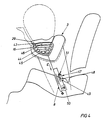
- the exemplary embodiment of the invention shown in FIG. 4 is also of essential importance.
- the gaming table 29 can be pivoted out of the contour of the retaining element 3 into a position shown in dashed lines about a swivel joint 43 which is arranged on the carrier 16.
- a generator 45 Inside the carrier 16 there is a folded bag-like container 44 which can be inflated by a generator 45.
- This generator 45 can be activated by impact sensors, not shown here, and is designed, for example, in the manner of a hybrid generator or a purely pyrotechnic gas generator.
- the bag-like container 44 can emerge from the contour of the carrier 16 through an opening 46 during the inflation process.
- the game table 29 is pivoted into the position shown in dashed lines, so that the sack-like container 44 can open freely in front of the child carried on the vehicle seat.
- An embodiment not shown in the drawing advantageously has bag-like containers in the side parts 2, 4, so that a good protective effect is achieved for the child in the event of a side impact.
- an actuating device 47 by which the restraining element 3 can be moved in the direction of the arrow E in the event of a vehicle accident.
- Such a movement which is directed against the pelvic and thoracic region and against the child's legs, cancels the child's freedom of movement, which is inherently desired in normal driving.
- the restraint element 3 should be moved towards the child as quickly as possible in the event of a vehicle accident, so that the child can participate in decelerating the vehicle at an early stage.
- the effect of the adjusting device 47 is therefore comparable to that of the belt tensioners known for seat belts and can be designed, for example, in the manner of a gas generator, by means of which a piston 48 can be activated, which is guided, for example, in a piston housing 49 of the articulated rod 8.
- the same impact sensors are expediently used for the activation of the actuating device 47 as for the activation of the generator 45.
- a force limiting device 50 and a freewheel device 51 assigned to the piston housing 49 are particularly noteworthy.
- the force limiting device 50 which is designed, for example, in the manner of a slip clutch, first ensures that the child moves the retaining element 3 in the direction of the arrow E no crush injuries. If the child then loads the restraining element 3 due to inertia, the freewheel device 51 locks, so that the restraining forces can be introduced via the adjusting device 47, the force limiting device 50 and the articulated rod 8 into body parts which are not numbered here. In this way, the force limiting device 50 thus protects the child from serious injuries even during the accident-related deceleration of the vehicle.
- the bag-like container 44 is sewn and folded in a particularly advantageous manner in such a way that it forms the outer contour of the retaining element 3 in the folded state.
- the seam guide is designed so that the inflation movement of the bag-like container against the pelvic and thoracic area and against the legs is directed in a vehicle accident.
- the dimension a ' is to be chosen so that the arms of the child are not torn up to an unacceptable level when the inflating movement of the sack-like container 44.
- FIGS. 4 and 5 are particularly suitable for largely avoiding the child's kinking movements and resulting injuries. Understandably, the invention is not limited only to the combinations of features of the exemplary embodiments shown in the drawing. It is entirely possible to combine features of one embodiment with features of the other embodiments.
- bag-like containers which are inflatable in a vehicle accident is conceivable not only in the exemplary embodiments according to the invention but also in generic vehicle seats, as are known, for example, from DE-PS 28 03 574 and DE-OS 37 16 619.
- a vehicle seat according to DE-OS 37 15 312 can be equipped with such a bag-like container.
Landscapes
- Engineering & Computer Science (AREA)
- Mechanical Engineering (AREA)
- Health & Medical Sciences (AREA)
- Child & Adolescent Psychology (AREA)
- General Health & Medical Sciences (AREA)
- Aviation & Aerospace Engineering (AREA)
- Transportation (AREA)
- Seats For Vehicles (AREA)
Applications Claiming Priority (4)
| Application Number | Priority Date | Filing Date | Title |
|---|---|---|---|
| DE3904877 | 1989-02-17 | ||
| DE3904877 | 1989-02-17 | ||
| DE3910133 | 1989-03-29 | ||
| DE3910133 | 1989-03-29 |
Publications (3)
| Publication Number | Publication Date |
|---|---|
| EP0383123A2 true EP0383123A2 (fr) | 1990-08-22 |
| EP0383123A3 EP0383123A3 (fr) | 1991-07-24 |
| EP0383123B1 EP0383123B1 (fr) | 1994-03-30 |
Family
ID=25877905
Family Applications (1)
| Application Number | Title | Priority Date | Filing Date |
|---|---|---|---|
| EP90102165A Expired - Lifetime EP0383123B1 (fr) | 1989-02-17 | 1990-02-03 | Siège pour véhicule |
Country Status (4)
| Country | Link |
|---|---|
| EP (1) | EP0383123B1 (fr) |
| JP (1) | JPH02249729A (fr) |
| DE (1) | DE59005148D1 (fr) |
| ES (1) | ES2051395T3 (fr) |
Cited By (11)
| Publication number | Priority date | Publication date | Assignee | Title |
|---|---|---|---|---|
| DE3929957A1 (de) * | 1989-09-08 | 1991-03-21 | Schmitz Gmbh & Co | Sitz, insbesondere fuer ein kraftfahrzeug |
| DE3929956A1 (de) * | 1989-09-08 | 1991-03-21 | Schmitz Gmbh & Co | Lagerung einer schwinge an einem arm, insbesondere an einem fahrzeugsitz |
| EP0518726A1 (fr) * | 1991-06-11 | 1992-12-16 | Bertrand Faure Automobile "B.F.A." | Dispositif d'une réhausse d'un coussin de siège de véhicule comprenant un verrouillage de sécurité |
| DE4343108C1 (de) * | 1993-12-17 | 1995-02-16 | Audi Ag | Rücksitzbank für ein Fahrzeug |
| FR2755411A1 (fr) * | 1996-11-06 | 1998-05-07 | Peugeot | Siege pour enfant adaptable sur un siege de vehicule automobile |
| FR2811274A1 (fr) * | 2000-07-07 | 2002-01-11 | Renolux France Ind | Dispositif de securite automobile pour enfant avec bouclier |
| DE102010042888A1 (de) * | 2010-10-25 | 2012-04-26 | Brose Fahrzeugteile Gmbh & Co. Kommanditgesellschaft, Coburg | Verstelleinrichtung für einen Fahrzeugsitz mit einem an einem Lagerblock gelagerten Lagerrohr |
| US9016785B2 (en) | 2010-10-25 | 2015-04-28 | Brose Fahrzeugteile Gmbh & Co. Kg, Coburg | Vehicle seat with a seat depth adjusting device |
| US10562422B2 (en) | 2017-02-08 | 2020-02-18 | Brose Fahrzeugteile Gmbh & Co. Kommanditgesellschaft, Coburg | Vehicle seat |
| CN111071115A (zh) * | 2020-01-20 | 2020-04-28 | 天台县有成汽车用品有限公司 | 一种可减震转动式儿童安全座椅 |
| US20220118934A1 (en) * | 2017-08-25 | 2022-04-21 | Cybex Gmbh | Child safety seat for attaching to a motor vehicle seat |
Families Citing this family (1)
| Publication number | Priority date | Publication date | Assignee | Title |
|---|---|---|---|---|
| DE4418028B4 (de) * | 1994-05-25 | 2006-03-23 | Volkswagen Ag | Kinderrückhaltesystem |
Citations (8)
| Publication number | Priority date | Publication date | Assignee | Title |
|---|---|---|---|---|
| FR2212800A5 (fr) * | 1972-12-09 | 1974-07-26 | Braun Ag | |
| FR2393703A1 (fr) * | 1977-06-07 | 1979-01-05 | Stahl Carl Gmbh Co Kg | Dispositif de retenue pour sieges de securite adaptables sur des sieges ordinaires de vehicules automobiles, en particulier pour sieges d'enfant |
| FR2274468B1 (fr) * | 1974-06-14 | 1979-02-09 | Faure Bertrand Ind | |
| US4159127A (en) * | 1975-11-19 | 1979-06-26 | Romer-Wingard Autogurte Gmbh | Safety apparatus for restraining a seated occupant in a vehicle |
| EP0003354A1 (fr) * | 1978-01-27 | 1979-08-08 | AUDI NSU AUTO UNION Aktiengesellschaft | Banquette arrière pour automobiles |
| JPS62134340A (ja) * | 1985-12-05 | 1987-06-17 | Nippon Soken Inc | 車両用シ−ト |
| DE3716619A1 (de) * | 1986-05-31 | 1987-12-03 | Volkswagen Ag | Sitz fuer fahrzeuge, insbesondere personenkraftfahrzeuge |
| JPS63149241A (ja) * | 1986-12-12 | 1988-06-22 | Daihatsu Motor Co Ltd | 車両の座席装置 |
-
1990
- 1990-02-03 EP EP90102165A patent/EP0383123B1/fr not_active Expired - Lifetime
- 1990-02-03 ES ES90102165T patent/ES2051395T3/es not_active Expired - Lifetime
- 1990-02-03 DE DE90102165T patent/DE59005148D1/de not_active Expired - Fee Related
- 1990-02-16 JP JP2034034A patent/JPH02249729A/ja active Pending
Patent Citations (8)
| Publication number | Priority date | Publication date | Assignee | Title |
|---|---|---|---|---|
| FR2212800A5 (fr) * | 1972-12-09 | 1974-07-26 | Braun Ag | |
| FR2274468B1 (fr) * | 1974-06-14 | 1979-02-09 | Faure Bertrand Ind | |
| US4159127A (en) * | 1975-11-19 | 1979-06-26 | Romer-Wingard Autogurte Gmbh | Safety apparatus for restraining a seated occupant in a vehicle |
| FR2393703A1 (fr) * | 1977-06-07 | 1979-01-05 | Stahl Carl Gmbh Co Kg | Dispositif de retenue pour sieges de securite adaptables sur des sieges ordinaires de vehicules automobiles, en particulier pour sieges d'enfant |
| EP0003354A1 (fr) * | 1978-01-27 | 1979-08-08 | AUDI NSU AUTO UNION Aktiengesellschaft | Banquette arrière pour automobiles |
| JPS62134340A (ja) * | 1985-12-05 | 1987-06-17 | Nippon Soken Inc | 車両用シ−ト |
| DE3716619A1 (de) * | 1986-05-31 | 1987-12-03 | Volkswagen Ag | Sitz fuer fahrzeuge, insbesondere personenkraftfahrzeuge |
| JPS63149241A (ja) * | 1986-12-12 | 1988-06-22 | Daihatsu Motor Co Ltd | 車両の座席装置 |
Non-Patent Citations (2)
| Title |
|---|
| PATENT ABSTRACTS OF JAPAN vol. 11, no. 356 (M-644)(2803) 20 November 1987, & JP-A-62 134340 (NIPPON SOKEN) 17 Juni 1987, * |
| PATENT ABSTRACTS OF JAPAN vol. 12, no. 409 (M-758)(3256) 28 Oktober 1988, & JP-A-63 149241 (DAIHATSU MOTOR) 22 Juni 1988, * |
Cited By (15)
| Publication number | Priority date | Publication date | Assignee | Title |
|---|---|---|---|---|
| DE3929957A1 (de) * | 1989-09-08 | 1991-03-21 | Schmitz Gmbh & Co | Sitz, insbesondere fuer ein kraftfahrzeug |
| DE3929956A1 (de) * | 1989-09-08 | 1991-03-21 | Schmitz Gmbh & Co | Lagerung einer schwinge an einem arm, insbesondere an einem fahrzeugsitz |
| EP0518726A1 (fr) * | 1991-06-11 | 1992-12-16 | Bertrand Faure Automobile "B.F.A." | Dispositif d'une réhausse d'un coussin de siège de véhicule comprenant un verrouillage de sécurité |
| FR2677588A1 (fr) * | 1991-06-11 | 1992-12-18 | Faure Bertrand Automobile | Dispositif d'une rehausse d'un coussin de siege de vehicule comprenant un verrouillage de securite. |
| DE4343108C1 (de) * | 1993-12-17 | 1995-02-16 | Audi Ag | Rücksitzbank für ein Fahrzeug |
| US5971479A (en) * | 1996-11-06 | 1999-10-26 | Automobiles Peugeot | Infant vehicle seat |
| FR2755411A1 (fr) * | 1996-11-06 | 1998-05-07 | Peugeot | Siege pour enfant adaptable sur un siege de vehicule automobile |
| FR2811274A1 (fr) * | 2000-07-07 | 2002-01-11 | Renolux France Ind | Dispositif de securite automobile pour enfant avec bouclier |
| DE102010042888A1 (de) * | 2010-10-25 | 2012-04-26 | Brose Fahrzeugteile Gmbh & Co. Kommanditgesellschaft, Coburg | Verstelleinrichtung für einen Fahrzeugsitz mit einem an einem Lagerblock gelagerten Lagerrohr |
| US9016785B2 (en) | 2010-10-25 | 2015-04-28 | Brose Fahrzeugteile Gmbh & Co. Kg, Coburg | Vehicle seat with a seat depth adjusting device |
| DE102010042888B4 (de) * | 2010-10-25 | 2019-04-25 | Brose Fahrzeugteile Gmbh & Co. Kommanditgesellschaft, Coburg | Baugruppe einer Verstelleinrichtung für einen Fahrzeugsitz mit einem an einem Lagerbock gelagerten Lagerrohr |
| US10562422B2 (en) | 2017-02-08 | 2020-02-18 | Brose Fahrzeugteile Gmbh & Co. Kommanditgesellschaft, Coburg | Vehicle seat |
| US20220118934A1 (en) * | 2017-08-25 | 2022-04-21 | Cybex Gmbh | Child safety seat for attaching to a motor vehicle seat |
| CN111071115A (zh) * | 2020-01-20 | 2020-04-28 | 天台县有成汽车用品有限公司 | 一种可减震转动式儿童安全座椅 |
| CN111071115B (zh) * | 2020-01-20 | 2021-01-12 | 上海远颂汽车技术有限公司 | 一种可减震转动式儿童安全座椅 |
Also Published As
| Publication number | Publication date |
|---|---|
| DE59005148D1 (de) | 1994-05-05 |
| EP0383123A3 (fr) | 1991-07-24 |
| JPH02249729A (ja) | 1990-10-05 |
| EP0383123B1 (fr) | 1994-03-30 |
| ES2051395T3 (es) | 1994-06-16 |
Similar Documents
| Publication | Publication Date | Title |
|---|---|---|
| DE69304145T2 (de) | Sitz und seine Verwendung in einem Fahrzeug | |
| DE2410193C2 (fr) | ||
| WO2020156953A1 (fr) | Ensemble sac gonflable destiné à un système de retenue d'un occupant de véhicule automobile | |
| EP0003354A1 (fr) | Banquette arrière pour automobiles | |
| DE19711944C2 (de) | Fahrzeugsitz | |
| DE2551419A1 (de) | Vorrichtung zum sichern von insassen in kraftfahrzeugen | |
| DE3445353A1 (de) | Fahrzeugsitz | |
| DE102018204461A1 (de) | Fahrzeugsitz | |
| EP0383123B1 (fr) | Siège pour véhicule | |
| DE102006016270A1 (de) | Kopfstütze für Kraftfahrzeugsitze | |
| DE19943595A1 (de) | Fahrzeugsitz, insbesondere Kraftahrzeugsitz | |
| DE19540962C2 (de) | KFZ-Kinder-Sicherheitssitz | |
| DE3800896A1 (de) | Sicherheitspersonenkraftwagen mit zusaetzlichen schutzeinrichtungen fuer die fahrzeuginsassen | |
| DE2803574C2 (de) | Rücksitzbank für Kraftfahrzeuge | |
| DE2709005C3 (de) | Fahrzeugsitz, insbesondere in Kraftfahrzeugen | |
| DE2147248C2 (de) | Schalenförmiger Kindersitz für Fahrzeuge, insbesondere Kraftwagen | |
| WO2018202802A1 (fr) | Siège de véhicule | |
| EP0403853B1 (fr) | Dispositif et méthode de protection d'une personne, en particulier d'un petit enfant, dans un véhicule automobile | |
| EP3697689B1 (fr) | File de sièges d'avion doté des unités de retenue multipoint | |
| DE20117794U1 (de) | Knierückhaltevorrichtung für einen Fahrer | |
| DE102019118841A1 (de) | Fahrzeuginsassen-Schutzsystem | |
| DE69401239T2 (de) | Kraftfahrzeugsitz | |
| DE4342959C2 (de) | Fahrzeugsitz | |
| EP0479006A1 (fr) | Siège pour un véhicule | |
| EP1394003A2 (fr) | Dispositif de retenue |
Legal Events
| Date | Code | Title | Description |
|---|---|---|---|
| PUAI | Public reference made under article 153(3) epc to a published international application that has entered the european phase |
Free format text: ORIGINAL CODE: 0009012 |
|
| AK | Designated contracting states |
Kind code of ref document: A2 Designated state(s): DE ES FR IT SE |
|
| PUAL | Search report despatched |
Free format text: ORIGINAL CODE: 0009013 |
|
| AK | Designated contracting states |
Kind code of ref document: A3 Designated state(s): DE ES FR IT SE |
|
| 17P | Request for examination filed |
Effective date: 19910613 |
|
| 17Q | First examination report despatched |
Effective date: 19930113 |
|
| GRAA | (expected) grant |
Free format text: ORIGINAL CODE: 0009210 |
|
| AK | Designated contracting states |
Kind code of ref document: B1 Designated state(s): DE ES FR IT SE |
|
| REF | Corresponds to: |
Ref document number: 59005148 Country of ref document: DE Date of ref document: 19940505 |
|
| REG | Reference to a national code |
Ref country code: ES Ref legal event code: FG2A Ref document number: 2051395 Country of ref document: ES Kind code of ref document: T3 |
|
| ET | Fr: translation filed | ||
| ITF | It: translation for a ep patent filed | ||
| EAL | Se: european patent in force in sweden |
Ref document number: 90102165.9 |
|
| PLBE | No opposition filed within time limit |
Free format text: ORIGINAL CODE: 0009261 |
|
| STAA | Information on the status of an ep patent application or granted ep patent |
Free format text: STATUS: NO OPPOSITION FILED WITHIN TIME LIMIT |
|
| 26N | No opposition filed | ||
| PGFP | Annual fee paid to national office [announced via postgrant information from national office to epo] |
Ref country code: ES Payment date: 20040209 Year of fee payment: 15 |
|
| PG25 | Lapsed in a contracting state [announced via postgrant information from national office to epo] |
Ref country code: IT Free format text: LAPSE BECAUSE OF NON-PAYMENT OF DUE FEES Effective date: 20050203 |
|
| PG25 | Lapsed in a contracting state [announced via postgrant information from national office to epo] |
Ref country code: ES Free format text: LAPSE BECAUSE OF NON-PAYMENT OF DUE FEES Effective date: 20050204 |
|
| PGFP | Annual fee paid to national office [announced via postgrant information from national office to epo] |
Ref country code: FR Payment date: 20050216 Year of fee payment: 16 |
|
| PGFP | Annual fee paid to national office [announced via postgrant information from national office to epo] |
Ref country code: SE Payment date: 20050221 Year of fee payment: 16 |
|
| PGFP | Annual fee paid to national office [announced via postgrant information from national office to epo] |
Ref country code: DE Payment date: 20050228 Year of fee payment: 16 |
|
| PG25 | Lapsed in a contracting state [announced via postgrant information from national office to epo] |
Ref country code: SE Free format text: LAPSE BECAUSE OF NON-PAYMENT OF DUE FEES Effective date: 20060204 |
|
| REG | Reference to a national code |
Ref country code: ES Ref legal event code: FD2A Effective date: 20050204 |
|
| PG25 | Lapsed in a contracting state [announced via postgrant information from national office to epo] |
Ref country code: DE Free format text: LAPSE BECAUSE OF NON-PAYMENT OF DUE FEES Effective date: 20060901 |
|
| EUG | Se: european patent has lapsed | ||
| REG | Reference to a national code |
Ref country code: FR Ref legal event code: ST Effective date: 20061031 |
|
| PG25 | Lapsed in a contracting state [announced via postgrant information from national office to epo] |
Ref country code: FR Free format text: LAPSE BECAUSE OF NON-PAYMENT OF DUE FEES Effective date: 20060228 |