EP0379926B1 - Einlassleitungssystem für Kraftmaschine mit mehreren Zylindern - Google Patents
Einlassleitungssystem für Kraftmaschine mit mehreren Zylindern Download PDFInfo
- Publication number
- EP0379926B1 EP0379926B1 EP90100763A EP90100763A EP0379926B1 EP 0379926 B1 EP0379926 B1 EP 0379926B1 EP 90100763 A EP90100763 A EP 90100763A EP 90100763 A EP90100763 A EP 90100763A EP 0379926 B1 EP0379926 B1 EP 0379926B1
- Authority
- EP
- European Patent Office
- Prior art keywords
- intake system
- resonance
- intake
- upstream side
- muffler
- Prior art date
- Legal status (The legal status is an assumption and is not a legal conclusion. Google has not performed a legal analysis and makes no representation as to the accuracy of the status listed.)
- Expired - Lifetime
Links
- 238000011144 upstream manufacturing Methods 0.000 claims description 38
- 230000000694 effects Effects 0.000 description 6
- 101000878457 Macrocallista nimbosa FMRFamide Proteins 0.000 description 2
- 230000002411 adverse Effects 0.000 description 2
- 239000000446 fuel Substances 0.000 description 2
- 238000002347 injection Methods 0.000 description 2
- 239000007924 injection Substances 0.000 description 2
- 230000010355 oscillation Effects 0.000 description 2
- 230000010349 pulsation Effects 0.000 description 2
- 230000015572 biosynthetic process Effects 0.000 description 1
- XLYOFNOQVPJJNP-UHFFFAOYSA-N water Substances O XLYOFNOQVPJJNP-UHFFFAOYSA-N 0.000 description 1
Images

Classifications
-
- F—MECHANICAL ENGINEERING; LIGHTING; HEATING; WEAPONS; BLASTING
- F02—COMBUSTION ENGINES; HOT-GAS OR COMBUSTION-PRODUCT ENGINE PLANTS
- F02M—SUPPLYING COMBUSTION ENGINES IN GENERAL WITH COMBUSTIBLE MIXTURES OR CONSTITUENTS THEREOF
- F02M35/00—Combustion-air cleaners, air intakes, intake silencers, or induction systems specially adapted for, or arranged on, internal-combustion engines
- F02M35/12—Intake silencers ; Sound modulation, transmission or amplification
- F02M35/1255—Intake silencers ; Sound modulation, transmission or amplification using resonance
- F02M35/1261—Helmholtz resonators
-
- F—MECHANICAL ENGINEERING; LIGHTING; HEATING; WEAPONS; BLASTING
- F02—COMBUSTION ENGINES; HOT-GAS OR COMBUSTION-PRODUCT ENGINE PLANTS
- F02M—SUPPLYING COMBUSTION ENGINES IN GENERAL WITH COMBUSTIBLE MIXTURES OR CONSTITUENTS THEREOF
- F02M35/00—Combustion-air cleaners, air intakes, intake silencers, or induction systems specially adapted for, or arranged on, internal-combustion engines
- F02M35/12—Intake silencers ; Sound modulation, transmission or amplification
- F02M35/1255—Intake silencers ; Sound modulation, transmission or amplification using resonance
- F02M35/1266—Intake silencers ; Sound modulation, transmission or amplification using resonance comprising multiple chambers or compartments
-
- B—PERFORMING OPERATIONS; TRANSPORTING
- B29—WORKING OF PLASTICS; WORKING OF SUBSTANCES IN A PLASTIC STATE IN GENERAL
- B29K—INDEXING SCHEME ASSOCIATED WITH SUBCLASSES B29B, B29C OR B29D, RELATING TO MOULDING MATERIALS OR TO MATERIALS FOR MOULDS, REINFORCEMENTS, FILLERS OR PREFORMED PARTS, e.g. INSERTS
- B29K2995/00—Properties of moulding materials, reinforcements, fillers, preformed parts or moulds
- B29K2995/0001—Properties of moulding materials, reinforcements, fillers, preformed parts or moulds having particular acoustical properties
Definitions
- This invention relates to an intake system for a multiple cylinder engine, and more particularly to an intake system for a multiple cylinder engine having an engine intake noise suppressing system for suppressing noise which is generated by the intake stroke of the engine.
- the resonance type muffler having a resonance frequency corresponding to the frequency of oscillation generated in the intake passage, as disclosed in Japanese Unexamined Patent Publication No. 54(1979)-9317.
- the air cleaner generally has a relatively large volume and cuts off the intake noise. Accordingly, the provisions described above are made for the resonance which occurs in the intake passage upstream of the air cleaner or the intake passage downstream of the same.
- the discrete intake passages which connect the respective cylinders to the common intake passage have come to occupy a larger space in the engine room, and the volume of the air cleaner has been reduced.
- a small volume air cleaner is apt to be used.
- the volume of the air cleaner which functions as an expansion type muffler, is small, low frequency range intake noise cannot be cut off.
- a resonator chamber for attenuating noise in the low-frequency range and, in addition, a side branch tube for reducing the high-frequency noise are connected with the intake air passage upstream of the air cleaner which forms the enlarged volume chamber.
- both resonators open into the intake passage there is an increased risk that resonance might occur, for example, at a frequency twice as high as the frequency to be suppressed. This means that, by the resonator chamber determined to suppress low frequency noise, additional noise in an intermediate frequency range is created.
- a first resonator for eliminating noise of a lower frequency is placed between a surge tank and an air cleaner, while a second resonator for eliminating noise of a higher frequency is placed upstream of the air cleaner, both resonators being connected directly to the air intake tube.
- the primary object of the present invention is to provide an intake system for a multiple cylinder engine according to the first part of claim 1 in which the engine intake noise can be cut off over a wide frequency range.
- the muffler opens to the air cleaner, a muffling effect which is the maximum in the range where the air-tightness of the muffler need not be ensured can be obtained.
- the engine intake noise includes low frequency noise which is generated by resonance of the whole intake passage, intermediate frequency noise which is generated by resonance of the discrete intake passages, and high frequency noise which is air flow noise, and it is not preferred that the other noises are increased when the low frequency noise is muffled.
- the intermediate frequency noise is increased due to resonance of the portion of the intake passage on opposite sides of the resonance muffler though the low frequency noise can be suppressed.
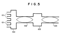
- the intake system comprises a surge tank 100 formed by the merging portion of the discrete passages 101, a downstream side portion 102 of a common intake passage, an air cleaner 103 and an upstream side portion 104 of the common intake passage, stationary vibration (intermediate frequency vibration) having nodes at the surge tank 100, the air cleaner (enlarged volume chamber) and the upstream end of the upstream side portion 104 (at which the upstream side portion 104 opens to the atmosphere) is generated.
- the resonance muffler enhances the vibration having a frequency twice the frequncy of the vibration which the resonance muffler suppresses. Accordingly, if the resonance muffler opens to the intake passage, the resonance muffler enhances the stationary vibration shown in Figure 5.
- the frequency twice the low frequency is an intermediate frequency and accordingly, the intermediate frequency noise is enhanced when the resonance muffler opens to the intake passage.
- the resonance muffler opens to the air cleaner (enlarged volume chamber), where the stationary wave has a node, as in the present invention, the intermediate frequency noise cannot be enhanced.
- the intake system has a throttle valve which is disposed close to the merging portion of the discrete intake passages in the upstream side intake system, and another (a second) resonance muffler which communicates with an enlarged volume chamber formed in the intake system downstream of the throttle valve and has a resonance frequency which corresponds to the fundamental resonance frequency of the upstream side intake system.
- the more downstream a resonance muffler which muffles the intake noise having a frequency corresponding to the fundamental resonance frequency of an intake passage opens to the intake passage the more the muffling effect of the muffler is. Further, the more the capacity of the muffler is, the more the muffling effect is.
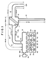
- an engine 1 has first to fourth cylinders 2a to 2d which are respectively provided with intake ports 3a to 3d and exhaust ports 4a to 4d. Though not shown, the intake ports 3a to 3d and the exhaust ports 4a to 4d are opened and closed by intake valves and exhaust valves.
- the intake ports 3a to 3d communicates with a surge tank 6 respectively by way of discrete intake passages 5a to 5d.
- a fuel injection valve 7 is disposed in each of the discrete intake passages 5a to 5d.
- a first portion 8 of a common intake passage is connected to the surge tank 6 at its downstream end and to an air cleaner 9 at its upstream end.
- the air cleaner 9 forms an enlarged volume chamber.
- a throttle 10 is provided in the first portion 8 of the common intake passage near the surge tank 6, and an airflow meter 11 is provided in the first portion 8 near the air cleaner 9.
- a second portion 12 of the common intake passage communicates with the air cleaner 9 at its downstream end and opens to the atmosphere at its upstream end(an opening 12a).
- the first and second portions 8 and 12 of the common intake passage and the air cleaner 9 forms an upstream side intake system 13.
- a first resonator 15 which is of a side branch type is connected to the air cleaner 9 at one end. The other end of the first resonator 15 is closed.
- the fundamental resonance frequency fo of the quarter-wave vibration which has a node at the upstream end of the upstream side intake system 13 and an antinode at the downstream end is equal to 360/4 (90Hz). Since two intake strokes occur for each revolution of the crankshaft in a four-cylinder in-line engine, the frequency of the pulsation of intake air which occurs in the upstream side intake system becomes 90Hz and resonance sound is generated when the engine speed is 2700rpm, i.e., when the engine makes 45 revolutions a second.
- the first resonator 15 has a lowest degree resonance frequency which is substantially equal to the fundamental resonance frequency fo.
- a second resonator 16 which is a Helmholtz resonator having a resonance frequency of 90Hz is connected to the surge tank 6.
- a third resonator 17 which is of the Helmholtz type is connected to an intermediate portion of the first portion 8 of the common intake passage.
- the third resonator 17 has a resonance chamber 17a which communicates with the first portion 8 by way of an opening 17b.
- the length of the first portion 8 is about 45cm and the resonance frequency of the third resonator 17 is about 330Hz which corresponds to the resonance frequency of the first portion 8.
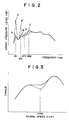
- the solid line shows the relation between the sound pressure level and the frequency in the intake system of this embodiment (i.e., in the intake system with the first to third resonators 15 to 17), and the broken line shows that in the intake system without the resonators 15 to 17.
- the sound pressure level peak at the resonance frequency of the upstream side intake system which would be at A′ (about 90dB) without the first and second resonators 15 and 16 is lowered to A (about 75dB) by the resonators 15 and 16.
- the sound pressure level peak at the resonance frequency of the first portion which would be at B′ without the third resonator 17 is lowered to B by the resonator 17.
- a peak C is produced by the third resonator 17, the peak C is low and the adverse effect of the resonator 17 is negligible.
- the resonance of the second portion 12 of the common intake passage produces a peak D.
- the intake system of this embodiment contributes to improvement of the engine speed-torque characteristics. That is, when the length of the discrete intake passages and other factors of the intake system are selected so that an inertia supercharging effect can be obtained in both the low engine speed range and the high engine speed range, a torque characteristic curve as shown by the broken line in Figure 3 is obtained if the intake system is not provided with the resonators 15 and 16. On the other hand, in the intake system of this embodiment (with the resonators 15 and 16), the bottom of the torque near 2700rpm is raised and a smooth torque characteristic is obtained.
- the intake system is provided with the three resonators
- the intake system may be only provided with a single resonator so long as it opens to an enlarged volume chamber formed in the intake system upstream of the air cleaner inclusive of the air cleaner and has a resonance frequency which corresponds to the fundamental resonance frequency of the upstream side intake system as can be understood from Figure 4, in which the solid line shows the relation between the sound pressure level and the frequency in an intake system with a single resonator which opens to the air cleaner, and the broken line shows that in an intake system without any resonator.
Landscapes
- Engineering & Computer Science (AREA)
- Chemical & Material Sciences (AREA)
- Combustion & Propulsion (AREA)
- Mechanical Engineering (AREA)
- General Engineering & Computer Science (AREA)
- Characterised By The Charging Evacuation (AREA)
Claims (5)
- Ansaugsystem für eine Mehrzylinder-Maschine mit einer Mehrzahl von Einzel-Ansaugleitungen (5a bis 5d), die jeweils mit den Zylindern (2a bis 2d) der Maschine über ihre stromabseitigen Enden verbunden sind und an ihren stromaufseitigen Enden in einen Sammelbehälter (6) übergehen, mit einer gemeinsamen Ansaugleitung (8, 12), die an ihrem stromabseitigen Ende mit dem Sammelbehälter (6) und über ihr stromaufseitiges Ende (12a) mit der Atmosphäre in Verbindung steht, wobei das Ansaugsystem ein stromaufseitiges Ansaugsystem (13), das den Teil des Ansaugsystems stromauf von dem Sammelbehälter (6) ausmacht und einen stromaufseitigen Ansaugabschnitt (9, 12) mit einem Luftfilter (9) enthält, sowie einen Resonanz-Schalldämpfer (15) umfasst, der mit dem stromaufseitigen Ansaugabschnitt (9, 12) des stromaufseitigen Ansaugsystems (13) in Verbindung steht,
dadurch gekennzeichnet,
daß der Resonanz-Schalldämpfer (15) eine Resonanzfrequenz entsprechend der Grundfrequenz des stromaufseitigen Ansaugsystems (13) hat und von einer Kammer (9) grösseren Volumens abzweigt, die den grössten Querschnitt in dem stromaufseitigen Ansaugsystem (13) hat. - Ansaugsystem nach Anspruch 1,
dadurch gekennzeichnet,
daß die Kammer (9) grösseren Volumens das Gehäuse des Luftfilters ist. - Ansaugsystem nach Anspruch 1 oder 2,
dadurch gekennzeichnet,
daß in dem stromaufseitigen Ansaugsystem (13) nahe dem Sammelbehälter (6) ein Drosselventil (10) angeordnet ist und daß ein zweiter Resonanz-Schalldämpfer (16) mit einer zweiten Kammer (6) grösseren Volumens verbunden ist, welche in dem stromaufseitigen Ansaugsystem (13) stromab von dem Drosselventil (10) ausgebildet ist und eine Resonanzfrequenz entsprechend der Grundfrequenz des stromaufseitigen Ansaugsystems (13) hat, wobei die erste und die zweite Kammer (9, 6) grösseren Volumens einen grösseren Querschnitt als die übrigen Teile des stromaufseitigen Ansaugsystems (13) haben. - Ansaugsystem nach Anspruch 3,
dadurch gekennzeichnet,
daß die zweite Kammer (6) grösseren Volumens der Sammelbehälter ist. - Ansaugsystem nach Anspruch 3 oder 4,
dadurch gekennzeichnet,
daß der erste Resonanz-Schalldämpfer (15) von der Art eines seitlich abzweigenden Staubodens und der zweite Resonanz-Schalldämpfer (16) ein Helmholtz-Schalldämpfer ist.
Applications Claiming Priority (2)
| Application Number | Priority Date | Filing Date | Title |
|---|---|---|---|
| JP1013231A JP3034258B2 (ja) | 1989-01-24 | 1989-01-24 | エンジンの吸気消音装置 |
| JP13231/89 | 1989-01-24 |
Publications (2)
| Publication Number | Publication Date |
|---|---|
| EP0379926A1 EP0379926A1 (de) | 1990-08-01 |
| EP0379926B1 true EP0379926B1 (de) | 1994-04-06 |
Family
ID=11827412
Family Applications (1)
| Application Number | Title | Priority Date | Filing Date |
|---|---|---|---|
| EP90100763A Expired - Lifetime EP0379926B1 (de) | 1989-01-24 | 1990-01-15 | Einlassleitungssystem für Kraftmaschine mit mehreren Zylindern |
Country Status (5)
| Country | Link |
|---|---|
| US (1) | US5002021A (de) |
| EP (1) | EP0379926B1 (de) |
| JP (1) | JP3034258B2 (de) |
| KR (1) | KR930004966B1 (de) |
| DE (1) | DE69007807T2 (de) |
Cited By (1)
| Publication number | Priority date | Publication date | Assignee | Title |
|---|---|---|---|---|
| CN106286045A (zh) * | 2015-06-23 | 2017-01-04 | 华晨汽车集团控股有限公司 | 增压发动机降噪进气系统 |
Families Citing this family (50)
| Publication number | Priority date | Publication date | Assignee | Title |
|---|---|---|---|---|
| NL8900977A (nl) * | 1989-04-19 | 1990-11-16 | Philips Nv | Werkwijze voor het vervaardigen van een optische vezel met een hermetische bedekking. |
| JP2753874B2 (ja) * | 1989-12-06 | 1998-05-20 | マツダ株式会社 | 多気筒エンジンの吸気装置 |
| JPH03202622A (ja) * | 1989-12-28 | 1991-09-04 | Mazda Motor Corp | 多気筒エンジンの吸気装置 |
| US5096010A (en) * | 1990-12-19 | 1992-03-17 | Ford Motor Company | Subframe induction noise reduction side-branch reactive silencer |
| GB2256674A (en) * | 1991-06-10 | 1992-12-16 | Ford Motor Co | Acoustic pipe coupling. |
| DE4216255A1 (de) * | 1992-05-16 | 1993-11-18 | Mann & Hummel Filter | Ansaugrohr und Verfahren zu dessen Herstellung |
| US5572966A (en) * | 1994-09-30 | 1996-11-12 | Siemens Electric Limited | Method and composite resonator for tuning an engine air induction system |
| US5575247A (en) * | 1995-02-01 | 1996-11-19 | Nippondenso Co., Ltd. | Air intake device for an internal combustion engine |
| USRE38708E1 (en) | 1995-07-11 | 2005-03-01 | United States Surgical Corporation | Disposable loading unit for surgical stapler |
| DE19618432A1 (de) * | 1996-05-08 | 1997-11-13 | Mann & Hummel Filter | Ansaugvorrichtung für einen Verbrennungsmotor |
| JP3787915B2 (ja) * | 1996-09-04 | 2006-06-21 | 豊田合成株式会社 | 内燃機関の吸気管 |
| KR100190883B1 (ko) * | 1996-12-13 | 1999-06-01 | 정몽규 | 가변형 흡기 리조네이터 구조 |
| JP3362626B2 (ja) * | 1997-01-31 | 2003-01-07 | スズキ株式会社 | エンジンの吸気装置 |
| DE19705273C1 (de) * | 1997-02-12 | 1998-03-05 | Porsche Ag | Sauganlage für eine Brennkraftmaschine |
| JP3420471B2 (ja) * | 1997-07-22 | 2003-06-23 | 本田技研工業株式会社 | 吸気消音装置 |
| DE19754840C2 (de) * | 1997-12-10 | 2001-01-18 | Mahle Filtersysteme Gmbh | Schalldämpferanordnung, insbesondere Ansaug-Schalldämpferanordnung |
| JP3441366B2 (ja) * | 1998-05-22 | 2003-09-02 | 東洋▲ろ▼機製造株式会社 | 内燃機関の吸気装置 |
| US6302752B1 (en) * | 1998-07-29 | 2001-10-16 | Yamaha Hatsudoki Kabushiki Kaisha | Induction system for watercraft engine |
| JP2000110678A (ja) * | 1998-10-08 | 2000-04-18 | Suzuki Motor Corp | 車両用エンジンの吸気消音装置 |
| DE19851636A1 (de) * | 1998-11-10 | 2000-05-11 | Asea Brown Boveri | Dämpfungsvorrichtung zur Reduzierung der Schwingungsamplitude akustischer Wellen für einen Brenner |
| US6447351B1 (en) | 1999-06-17 | 2002-09-10 | Yamaha Hatsudoki Kabushiki Kaisha | Vapor system arrangement for marine engine |
| JP2001090619A (ja) | 1999-09-24 | 2001-04-03 | Yamaha Motor Co Ltd | 小型船舶用エンジンの吸気装置 |
| US20020094274A1 (en) * | 2000-09-15 | 2002-07-18 | Terpay Gregory Weston | Passive device for noise reduction |
| JP4442740B2 (ja) * | 2000-10-17 | 2010-03-31 | ヤマハ発動機株式会社 | 船舶推進機の吸気装置 |
| US6796859B1 (en) * | 2000-11-16 | 2004-09-28 | Bombardier Recreational Products Inc. | Air intake silencer |
| JP3901483B2 (ja) * | 2001-10-04 | 2007-04-04 | ヤマハ発動機株式会社 | エンジンの吸気音調整構造及び排気音調整構造 |
| EP1479125A2 (de) | 2002-02-20 | 2004-11-24 | Acumentrics Corporation | Dichtung von brennstoffzellen und anordnung in einem stapel |
| US7107959B2 (en) * | 2002-05-16 | 2006-09-19 | Toyoda Gosei Co., Ltd. | Air intake apparatus |
| US6905002B2 (en) * | 2002-06-21 | 2005-06-14 | International Engine Intellectual Property Company, Llc | Acoustic wave attenuator for a rail |
| JP2004270559A (ja) | 2003-03-10 | 2004-09-30 | Honda Motor Co Ltd | 車両用吸気装置 |
| JP4357881B2 (ja) * | 2003-06-12 | 2009-11-04 | ヤマハ発動機株式会社 | 小型船舶 |
| US20050051384A1 (en) * | 2003-09-10 | 2005-03-10 | Breznik Evelyn A. | Air intake silencer |
| JP2005264735A (ja) * | 2004-03-16 | 2005-09-29 | Yamaha Marine Co Ltd | 過給機付きエンジン |
| DE102004016478A1 (de) | 2004-03-31 | 2005-10-20 | Mann & Hummel Gmbh | Ansaugsystem einer Brennkraftmaschine |
| JP2006002633A (ja) * | 2004-06-16 | 2006-01-05 | Yamaha Marine Co Ltd | 水ジェット推進艇 |
| JP2006037730A (ja) | 2004-07-22 | 2006-02-09 | Yamaha Marine Co Ltd | 過給式エンジンの吸気装置 |
| JP2006083713A (ja) | 2004-09-14 | 2006-03-30 | Yamaha Marine Co Ltd | 過給装置の潤滑構造 |
| US7523731B2 (en) * | 2004-09-29 | 2009-04-28 | Keihin Corporation | Intake system for internal combustion engine |
| JP2007062432A (ja) | 2005-08-29 | 2007-03-15 | Yamaha Marine Co Ltd | 小型滑走艇 |
| JP4614853B2 (ja) * | 2005-09-26 | 2011-01-19 | ヤマハ発動機株式会社 | 過給機の取付構造 |
| JP2008031918A (ja) * | 2006-07-28 | 2008-02-14 | Denso Corp | 吸気装置 |
| US20080093162A1 (en) * | 2006-10-23 | 2008-04-24 | Marocco Gregory M | Gas flow sound attenuation device |
| DE102007026416B4 (de) * | 2007-06-06 | 2014-09-04 | Audi Ag | Vorrichtung zur Beeinflussung des Ansauggeräusches einer Brennkraftmaschine |
| US7845466B2 (en) * | 2007-08-28 | 2010-12-07 | Visteon Global Technologies, Inc. | Sound generator with structurally and acoustically coupled sound radiation panel and method for manufacturing the same |
| KR100921112B1 (ko) * | 2007-11-20 | 2009-10-12 | 현대자동차주식회사 | 듀얼 인테이크 덕트 구조 |
| JP5791442B2 (ja) * | 2011-09-20 | 2015-10-07 | ダイハツ工業株式会社 | 内燃機関 |
| US20150247507A1 (en) * | 2014-02-28 | 2015-09-03 | Regal Beloit America, Inc. | Acoustic Shunt and Method of Attenuating Noise Generated in a Heater Venting System |
| US9677517B2 (en) * | 2015-05-01 | 2017-06-13 | Fca Us Llc | Dual path cool air inlet system |
| US10302052B2 (en) * | 2016-11-16 | 2019-05-28 | Ford Global Technologies, Llc | Vacuum actuated multi-frequency quarter-wave resonator for an internal combustion engine |
| CN108361132B (zh) * | 2018-01-18 | 2023-07-21 | 安徽合力股份有限公司 | 一种带有消音支管的叉车发动机进气系统 |
Citations (2)
| Publication number | Priority date | Publication date | Assignee | Title |
|---|---|---|---|---|
| EP0192457A1 (de) * | 1985-02-18 | 1986-08-27 | Honda Giken Kogyo Kabushiki Kaisha | Schalldämpfer |
| EP0376299A1 (de) * | 1988-12-28 | 1990-07-04 | Mazda Motor Corporation | Ansaugvorrichtung für Kraftmaschine |
Family Cites Families (14)
| Publication number | Priority date | Publication date | Assignee | Title |
|---|---|---|---|---|
| US3990415A (en) * | 1972-12-01 | 1976-11-09 | Regie Nationale Des Usines Renault | Intake passages of internal combustion engines |
| JPS549317A (en) * | 1977-06-23 | 1979-01-24 | Honda Motor Co Ltd | Suction noise muffler for internal combustion engine |
| HU175877B (en) * | 1978-07-07 | 1980-11-28 | Autoipari Kutato Intezet | Fresh gas duct system of resanator for internal combustion piston engines |
| HU182843B (en) * | 1978-12-21 | 1984-03-28 | Autoipari Kutato Fejlesztoe | Internal combustion piston engine with fresh gas conduit system boosting the supercharging of cylynders |
| JPS56113042A (en) * | 1980-02-08 | 1981-09-05 | Yamaha Motor Co Ltd | Engine for vehicle |
| JPS58172451A (ja) * | 1982-04-02 | 1983-10-11 | Nissan Motor Co Ltd | 自動車用エンジンの吸気装置 |
| US4664076A (en) * | 1984-06-15 | 1987-05-12 | Honda Giken Kogyo Kabushiki Kaisha | Intake system for internal combustion engine |
| JPS61190158A (ja) * | 1985-02-18 | 1986-08-23 | Honda Motor Co Ltd | 内燃機関用吸気系消音装置 |
| JPS61192560A (ja) * | 1985-02-20 | 1986-08-27 | Hitachi Ltd | ドット制御装置 |
| JPS62214222A (ja) * | 1986-03-14 | 1987-09-21 | Yamaha Motor Co Ltd | エンジンの吸気装置 |
| JPS6362219A (ja) * | 1986-09-02 | 1988-03-18 | Toshiba Corp | 半導体基板の接合方法 |
| JPS63219866A (ja) * | 1987-03-10 | 1988-09-13 | Honda Motor Co Ltd | 内燃機関の吸気装置 |
| JP2549383B2 (ja) * | 1987-06-26 | 1996-10-30 | マツダ株式会社 | エンジンの吸気装置 |
| JPH01117920A (ja) * | 1987-10-30 | 1989-05-10 | Mazda Motor Corp | V型エンジンの吸気装置 |
-
1989
- 1989-01-24 JP JP1013231A patent/JP3034258B2/ja not_active Expired - Fee Related
-
1990
- 1990-01-15 DE DE69007807T patent/DE69007807T2/de not_active Expired - Fee Related
- 1990-01-15 EP EP90100763A patent/EP0379926B1/de not_active Expired - Lifetime
- 1990-01-19 US US07/467,498 patent/US5002021A/en not_active Expired - Lifetime
- 1990-01-23 KR KR1019900000743A patent/KR930004966B1/ko not_active IP Right Cessation
Patent Citations (2)
| Publication number | Priority date | Publication date | Assignee | Title |
|---|---|---|---|---|
| EP0192457A1 (de) * | 1985-02-18 | 1986-08-27 | Honda Giken Kogyo Kabushiki Kaisha | Schalldämpfer |
| EP0376299A1 (de) * | 1988-12-28 | 1990-07-04 | Mazda Motor Corporation | Ansaugvorrichtung für Kraftmaschine |
Non-Patent Citations (1)
| Title |
|---|
| PATENT ABSTRACTS OF JAPAN, vol. 11, No. 14 (M-553) (2461), 14 January 1987; & JP-A-61 190 158 (HONDA) 23.08.1986 * |
Cited By (1)
| Publication number | Priority date | Publication date | Assignee | Title |
|---|---|---|---|---|
| CN106286045A (zh) * | 2015-06-23 | 2017-01-04 | 华晨汽车集团控股有限公司 | 增压发动机降噪进气系统 |
Also Published As
| Publication number | Publication date |
|---|---|
| KR930004966B1 (ko) | 1993-06-11 |
| JPH02196157A (ja) | 1990-08-02 |
| JP3034258B2 (ja) | 2000-04-17 |
| DE69007807T2 (de) | 1994-07-28 |
| EP0379926A1 (de) | 1990-08-01 |
| US5002021A (en) | 1991-03-26 |
| DE69007807D1 (de) | 1994-05-11 |
| KR900011979A (ko) | 1990-08-02 |
Similar Documents
| Publication | Publication Date | Title |
|---|---|---|
| EP0379926B1 (de) | Einlassleitungssystem für Kraftmaschine mit mehreren Zylindern | |
| US5014816A (en) | Silencer for gas induction and exhaust systems | |
| EP0859906B1 (de) | Ein schalldämpfer für ansaugsystem oder abgassystem | |
| US6752240B1 (en) | Sound attenuator for a supercharged marine propulsion device | |
| EP0889228B1 (de) | Ansauggeräuschdämpfer für eine Brennkraftmaschine | |
| US5572966A (en) | Method and composite resonator for tuning an engine air induction system | |
| US4192404A (en) | Muffler for internal combustion engines | |
| JPS61116021A (ja) | エンジンの吸気装置 | |
| JPH01182515A (ja) | 自動車の排気消音装置 | |
| US4735177A (en) | Intake system for internal combustion engine | |
| US5530214A (en) | Venturi muffler | |
| EP0768465B1 (de) | Gasverdichter | |
| EP0312979B1 (de) | Einlasssystem für Brennkraftmaschine in V-Bauart | |
| US10066589B2 (en) | Independent intake runner resonator system | |
| JPH09126074A (ja) | 分岐型チューブレゾネータ | |
| GB2111122A (en) | Silencer arrangement at the inlet of an I.C. engine air cleaner | |
| KR100250050B1 (ko) | V형 엔진의 가변 흡기시스템 | |
| JPH04209961A (ja) | 内燃機関の吸気装置 | |
| JPS5949361A (ja) | 内燃機関の吸気消音装置 | |
| RU2737014C1 (ru) | Двигатель внутреннего сгорания с системой впуска воздуха | |
| JP3163957B2 (ja) | エンジンの排気消音装置 | |
| JP3475651B2 (ja) | エアクリーナ装置 | |
| US4674277A (en) | Secondary air supply system for an engine exhaust gas purifying system | |
| JP3532079B2 (ja) | 内燃機関の吸気ダクト | |
| JP3325722B2 (ja) | エンジンの吸気装置 |
Legal Events
| Date | Code | Title | Description |
|---|---|---|---|
| PUAI | Public reference made under article 153(3) epc to a published international application that has entered the european phase |
Free format text: ORIGINAL CODE: 0009012 |
|
| AK | Designated contracting states |
Kind code of ref document: A1 Designated state(s): DE FR GB |
|
| 17P | Request for examination filed |
Effective date: 19900915 |
|
| 17Q | First examination report despatched |
Effective date: 19920306 |
|
| GRAA | (expected) grant |
Free format text: ORIGINAL CODE: 0009210 |
|
| AK | Designated contracting states |
Kind code of ref document: B1 Designated state(s): DE FR GB |
|
| REF | Corresponds to: |
Ref document number: 69007807 Country of ref document: DE Date of ref document: 19940511 |
|
| ET | Fr: translation filed | ||
| PLBE | No opposition filed within time limit |
Free format text: ORIGINAL CODE: 0009261 |
|
| STAA | Information on the status of an ep patent application or granted ep patent |
Free format text: STATUS: NO OPPOSITION FILED WITHIN TIME LIMIT |
|
| 26N | No opposition filed | ||
| REG | Reference to a national code |
Ref country code: GB Ref legal event code: IF02 |
|
| PGFP | Annual fee paid to national office [announced via postgrant information from national office to epo] |
Ref country code: FR Payment date: 20040108 Year of fee payment: 15 |
|
| PGFP | Annual fee paid to national office [announced via postgrant information from national office to epo] |
Ref country code: GB Payment date: 20040114 Year of fee payment: 15 |
|
| PG25 | Lapsed in a contracting state [announced via postgrant information from national office to epo] |
Ref country code: GB Free format text: LAPSE BECAUSE OF NON-PAYMENT OF DUE FEES Effective date: 20050115 |
|
| GBPC | Gb: european patent ceased through non-payment of renewal fee |
Effective date: 20050115 |
|
| PG25 | Lapsed in a contracting state [announced via postgrant information from national office to epo] |
Ref country code: FR Free format text: LAPSE BECAUSE OF NON-PAYMENT OF DUE FEES Effective date: 20050930 |
|
| REG | Reference to a national code |
Ref country code: FR Ref legal event code: ST |
|
| PGFP | Annual fee paid to national office [announced via postgrant information from national office to epo] |
Ref country code: DE Payment date: 20060112 Year of fee payment: 17 |
|
| PG25 | Lapsed in a contracting state [announced via postgrant information from national office to epo] |
Ref country code: DE Free format text: LAPSE BECAUSE OF NON-PAYMENT OF DUE FEES Effective date: 20070801 |