EP0379020A1 - Schaltvorrichtung zum Ein- und Ausschalten von Plattensägen - Google Patents
Schaltvorrichtung zum Ein- und Ausschalten von Plattensägen Download PDFInfo
- Publication number
- EP0379020A1 EP0379020A1 EP90100282A EP90100282A EP0379020A1 EP 0379020 A1 EP0379020 A1 EP 0379020A1 EP 90100282 A EP90100282 A EP 90100282A EP 90100282 A EP90100282 A EP 90100282A EP 0379020 A1 EP0379020 A1 EP 0379020A1
- Authority
- EP
- European Patent Office
- Prior art keywords
- switching device
- operator
- saws
- workpiece
- actuating member
- Prior art date
- Legal status (The legal status is an assumption and is not a legal conclusion. Google has not performed a legal analysis and makes no representation as to the accuracy of the status listed.)
- Ceased
Links
Images
Classifications
-
- B—PERFORMING OPERATIONS; TRANSPORTING
- B27—WORKING OR PRESERVING WOOD OR SIMILAR MATERIAL; NAILING OR STAPLING MACHINES IN GENERAL
- B27B—SAWS FOR WOOD OR SIMILAR MATERIAL; COMPONENTS OR ACCESSORIES THEREFOR
- B27B5/00—Sawing machines working with circular or cylindrical saw blades; Components or equipment therefor
- B27B5/02—Sawing machines working with circular or cylindrical saw blades; Components or equipment therefor characterised by a special purpose only
- B27B5/06—Sawing machines working with circular or cylindrical saw blades; Components or equipment therefor characterised by a special purpose only for dividing plates in parts of determined size, e.g. panels
-
- B—PERFORMING OPERATIONS; TRANSPORTING
- B23—MACHINE TOOLS; METAL-WORKING NOT OTHERWISE PROVIDED FOR
- B23D—PLANING; SLOTTING; SHEARING; BROACHING; SAWING; FILING; SCRAPING; LIKE OPERATIONS FOR WORKING METAL BY REMOVING MATERIAL, NOT OTHERWISE PROVIDED FOR
- B23D59/00—Accessories specially designed for sawing machines or sawing devices
- B23D59/001—Measuring or control devices, e.g. for automatic control of work feed pressure on band saw blade
-
- B—PERFORMING OPERATIONS; TRANSPORTING
- B23—MACHINE TOOLS; METAL-WORKING NOT OTHERWISE PROVIDED FOR
- B23Q—DETAILS, COMPONENTS, OR ACCESSORIES FOR MACHINE TOOLS, e.g. ARRANGEMENTS FOR COPYING OR CONTROLLING; MACHINE TOOLS IN GENERAL CHARACTERISED BY THE CONSTRUCTION OF PARTICULAR DETAILS OR COMPONENTS; COMBINATIONS OR ASSOCIATIONS OF METAL-WORKING MACHINES, NOT DIRECTED TO A PARTICULAR RESULT
- B23Q1/00—Members which are comprised in the general build-up of a form of machine, particularly relatively large fixed members
- B23Q1/0009—Energy-transferring means or control lines for movable machine parts; Control panels or boxes; Control parts
-
- Y—GENERAL TAGGING OF NEW TECHNOLOGICAL DEVELOPMENTS; GENERAL TAGGING OF CROSS-SECTIONAL TECHNOLOGIES SPANNING OVER SEVERAL SECTIONS OF THE IPC; TECHNICAL SUBJECTS COVERED BY FORMER USPC CROSS-REFERENCE ART COLLECTIONS [XRACs] AND DIGESTS
- Y10—TECHNICAL SUBJECTS COVERED BY FORMER USPC
- Y10T—TECHNICAL SUBJECTS COVERED BY FORMER US CLASSIFICATION
- Y10T74/00—Machine element or mechanism
- Y10T74/20—Control lever and linkage systems
- Y10T74/20396—Hand operated
-
- Y—GENERAL TAGGING OF NEW TECHNOLOGICAL DEVELOPMENTS; GENERAL TAGGING OF CROSS-SECTIONAL TECHNOLOGIES SPANNING OVER SEVERAL SECTIONS OF THE IPC; TECHNICAL SUBJECTS COVERED BY FORMER USPC CROSS-REFERENCE ART COLLECTIONS [XRACs] AND DIGESTS
- Y10—TECHNICAL SUBJECTS COVERED BY FORMER USPC
- Y10T—TECHNICAL SUBJECTS COVERED BY FORMER US CLASSIFICATION
- Y10T83/00—Cutting
- Y10T83/97—Miscellaneous
Definitions
- the invention relates to a switching device for switching table saws on and off with a workpiece table having at least two table plates arranged at a lateral distance from one another, which has an actuating element which can be actuated by an operator from any location between the table tops or from the rear end face of one of the table tops.
- Panel saws are usually controlled via a control panel which is arranged on the operating side, for example on a boom (brochure from Holzma Maschinenbau GmbH, 7260 Calw-Holzbronn, "Plattenschneider HPP 01", May 1987).
- this is usually equipped with an additional switching device in the form of a removable, via a cable with the Panel saw connected foot switch to be brought by the operator in question below the workpiece loading or transfer table into the most favorable operating position for them.
- the invention has for its object to avoid these disadvantages and to provide a switching device that can be reached and actuated from any position between the table tops or at least from the rear end of one of the table tops.
- This object is achieved according to the invention by means of a switching device of the type described at the outset in that the switching device is fixed to the table and in that its actuating element is arranged below the one table top, extends along one of the longitudinal edges of the table top lying opposite one another and has to be raised in order to trigger a switching operation.
- the arrangement according to the invention of the switching device on the workpiece loading or transfer table, or the design and arrangement of its actuating element on one of the table tops ensures that it grips between the table tops at any location of the operator or at a great distance from the control panel between the table tops - or can be actuated, but at the same time no switching operation can be triggered when the same touches pressure. For the operator, there is thus no need to have to find out about its exact position before actuating the switching device, which may become necessary; rather, it is able to switch off the panel saw immediately in the event of unforeseen events.
- the actuator can be formed, for example, by a tight rope.
- the same is preferably designed in the manner of a rod and is arranged to be pivotable about an axis parallel to its longitudinal axis. It is advantageous if the actuator, based on the longitudinal edge of the table top, can be pivoted outwards to initiate a switching operation. This ensures that no switching operation can be triggered even if the operator should bend over the longitudinal edge of the table top below which the actuator is located.
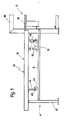
- a panel saw shown only partially in side view is designated as a whole by 10.
- a workpiece table designated as a whole by 12
- workpiece plates are fed by means of a workpiece feed device, which is attached to the side of the plate saw 10 opposite the workpiece table 12.
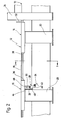
- the workpiece table 12 has, for example, two table tops 14 and 16 arranged at a lateral distance from one another, which, according to FIG. 1, have their right end on the machine table 18 the panel saw and are supported at their left end by means of a support foot 20.
- the table top 14 on the right in FIG. 2 is also assigned a side stop 22.
- 24 denotes one of the frame side stands of the panel saw 10.
- the other is labeled 26 in FIG. 1.
- the workpiece table 12 is assigned an electrical switching device, designated as a whole by 28, which, which is not shown in more detail, is connected to the control means for driving the panel saw 10.
- This switching device is designed and arranged in such a way that it can be operated quickly and safely by the operator concerned, provided that this is between the two tabletops 14 and 16, from any location.
- the switching device 28 is mounted, for example, on the workpiece table 12, for example below its table top 16. It has a stationary electrical switch 30, the switching element 32 of which can be actuated by an actuating element 34, which is preferably formed by a rod-shaped hollow profile and is arranged below the table top 16 in the region of the table top longitudinal edge 36 which lies opposite the table top longitudinal edge 38 of the table top 14.
- the rod-shaped actuating member 34 extends, as shown in FIG. 1, essentially over the entire length of the table top 16, is arranged parallel to the latter and is raised to actuate the electrical switch 30.
- the actuator 34 is pivotally mounted by means of two spaced apart mounting brackets 40 and 42 on corresponding bearing blocks 44 and 46 fastened to the underside of the table top 16, one of the bearing blocks at for example, on the bearing block 46 closest to the panel saw 10, the electrical switch 30 is fastened such that it can be actuated by the bearing bracket 42 when the rod-shaped actuating member 34 is pivoted upward in the direction of the arrow according to FIG. 2 via its switching member 32.
- the actuator 34 is pivotally mounted on the bearing blocks 44 and 46 about a pivot axis 48 parallel to its axis.
- This construction ensures that the rod-shaped actuating element 34 automatically returns to its lower starting position according to FIG. 2 after a switch has been actuated and that it is inadvertently touched, for example by the operator's knees, if the operator should bend over the table top 16. no switch operation can take place.
- the actuator 34 can be handled quickly and safely from any location of the operator between the two table tops 14, 16 in order to switch the panel saw on and off.
- the workpiece table 12 comprises, for example, three or more table tops spaced apart from one another, it is clear that a switching device 28 of the type explained can be provided between two adjacent table tops.
- a switching device 28 of the type explained can be provided between two adjacent table tops.
- both table tops 14 and 16 could each be equipped with a switching device 28.
Landscapes
- Engineering & Computer Science (AREA)
- Mechanical Engineering (AREA)
- Life Sciences & Earth Sciences (AREA)
- Wood Science & Technology (AREA)
- Forests & Forestry (AREA)
- Sawing (AREA)
Applications Claiming Priority (2)
| Application Number | Priority Date | Filing Date | Title |
|---|---|---|---|
| DE3901538 | 1989-01-20 | ||
| DE3901538A DE3901538C1 (enExample) | 1989-01-20 | 1989-01-20 |
Publications (1)
| Publication Number | Publication Date |
|---|---|
| EP0379020A1 true EP0379020A1 (de) | 1990-07-25 |
Family
ID=6372421
Family Applications (1)
| Application Number | Title | Priority Date | Filing Date |
|---|---|---|---|
| EP90100282A Ceased EP0379020A1 (de) | 1989-01-20 | 1990-01-08 | Schaltvorrichtung zum Ein- und Ausschalten von Plattensägen |
Country Status (3)
| Country | Link |
|---|---|
| US (1) | US5079393A (enExample) |
| EP (1) | EP0379020A1 (enExample) |
| DE (1) | DE3901538C1 (enExample) |
Cited By (1)
| Publication number | Priority date | Publication date | Assignee | Title |
|---|---|---|---|---|
| FR2705915A1 (fr) * | 1993-06-03 | 1994-12-09 | Guitton A | Dispositif d'arrêt d'urgence pour machine du type tour, fraiseuse, etc.... |
Citations (1)
| Publication number | Priority date | Publication date | Assignee | Title |
|---|---|---|---|---|
| AT385449B (de) * | 1986-07-23 | 1988-03-25 | Schelling & Co | Vorrichtung zum aufteilen von plattenfoermigen werkstuecken |
Family Cites Families (5)
| Publication number | Priority date | Publication date | Assignee | Title |
|---|---|---|---|---|
| US2255706A (en) * | 1941-03-06 | 1941-09-09 | Leon H Height | Automatic lathe stop switch |
| US3693773A (en) * | 1970-08-21 | 1972-09-26 | Black & Decker Mfg Co | Carriage stop for radial arm saw |
| US4358651A (en) * | 1981-02-12 | 1982-11-09 | Bristol Corporation | Machine safety guard |
| US4356369A (en) * | 1981-02-12 | 1982-10-26 | Bristol Corporation | Guard apparatus |
| US4359615A (en) * | 1981-08-14 | 1982-11-16 | Black & Decker Inc. | Switch and means to prevent unauthorized operation thereof |
-
1989
- 1989-01-20 DE DE3901538A patent/DE3901538C1/de not_active Expired
-
1990
- 1990-01-08 EP EP90100282A patent/EP0379020A1/de not_active Ceased
- 1990-01-16 US US07/465,029 patent/US5079393A/en not_active Expired - Fee Related
Patent Citations (1)
| Publication number | Priority date | Publication date | Assignee | Title |
|---|---|---|---|---|
| AT385449B (de) * | 1986-07-23 | 1988-03-25 | Schelling & Co | Vorrichtung zum aufteilen von plattenfoermigen werkstuecken |
Cited By (1)
| Publication number | Priority date | Publication date | Assignee | Title |
|---|---|---|---|---|
| FR2705915A1 (fr) * | 1993-06-03 | 1994-12-09 | Guitton A | Dispositif d'arrêt d'urgence pour machine du type tour, fraiseuse, etc.... |
Also Published As
| Publication number | Publication date |
|---|---|
| US5079393A (en) | 1992-01-07 |
| DE3901538C1 (enExample) | 1989-12-28 |
Similar Documents
| Publication | Publication Date | Title |
|---|---|---|
| EP0093318B1 (de) | Entschwartungsmaschine | |
| DE3832845C1 (en) | Assembly station having a positioning and holding apparatus | |
| EP0242762B1 (de) | Anordnung zum Zuführen von gestapeltem, blattförmigen Gut zu einer Weiterverarbeitungsstation, insbesondere Schneidstation | |
| DE29701967U1 (de) | Vorrichtung zum Abschneiden von Stahl | |
| DE1558352B1 (de) | Vorrichtung zum Einstelleneines Schneidwerkzeuges beim Unterteilen von metallischen Straengen,insbesondere Gussstraengen | |
| DE29608724U1 (de) | Vorrichtung zum Trennen von Glastafeln | |
| DE69820564T2 (de) | Maschine zum Schneiden von flächigen Körpern mit einem zweiten rotierbaren Tisch | |
| EP0379020A1 (de) | Schaltvorrichtung zum Ein- und Ausschalten von Plattensägen | |
| DE1013664B (de) | Vorrichtung zum Einstellen der Anlegemarken in einer Bogen bearbeitenden Maschine, wie Druckmaschine und Presse zum Schneiden von Papier oder Pappe | |
| EP0978357B1 (de) | Schneideanlage mit Schnittguttransportsystem | |
| DE1502774B2 (de) | Anschlagvorrichtung bei einer Schere, insbesondere Blechschere | |
| AT403263B (de) | Maschinentisch mit einer unterflurkreissäge | |
| DE2525263B1 (de) | Papierendeschaltvorrichtung fuer einen matrixdrucker | |
| DE3044060C2 (de) | Vorrichtung zum Entfleischen von Häuten | |
| DE2509014B1 (de) | Plattenaufteilsaege | |
| DE2446459C2 (de) | Bolzenschweißvorrichtung | |
| DE19647124A1 (de) | Beschickungsvorrichtung | |
| DE1286053B (de) | Messerfalzvorrichtung | |
| DE1801529C3 (de) | Vorrichtung zum Zuführen von stangenförmigen Werkstücken, bei Werkzeugmaschinen, insbesondere Drehautomaten | |
| DE4417047C2 (de) | Einrichtung zum Trennen von aneinander anliegenden, quergeteilten Plattenstreifen hinter der Trennlinie von Plattenaufteilsägen | |
| DE29517466U1 (de) | Schneidmaschine | |
| DE3040039C2 (de) | Klemmvorrichtung für eine Stranggieß-Brennschneidmaschine | |
| DE9013640U1 (de) | Vorschubvorrichtung zum Zuführen von Werkstückplatten in Plattensägen | |
| DE830059C (de) | Tisch fuer Eiswerke | |
| DE2019963A1 (de) | Einrichtung fuer Tafelscheren |
Legal Events
| Date | Code | Title | Description |
|---|---|---|---|
| PUAI | Public reference made under article 153(3) epc to a published international application that has entered the european phase |
Free format text: ORIGINAL CODE: 0009012 |
|
| AK | Designated contracting states |
Kind code of ref document: A1 Designated state(s): AT BE CH DE ES FR GB IT LI NL SE |
|
| 17P | Request for examination filed |
Effective date: 19900928 |
|
| 17Q | First examination report despatched |
Effective date: 19930312 |
|
| STAA | Information on the status of an ep patent application or granted ep patent |
Free format text: STATUS: THE APPLICATION HAS BEEN REFUSED |
|
| 18R | Application refused |
Effective date: 19930906 |