EP0378808A2 - Justierbares Kopfplatten-Zwischenbauteil - Google Patents
Justierbares Kopfplatten-Zwischenbauteil Download PDFInfo
- Publication number
- EP0378808A2 EP0378808A2 EP89123041A EP89123041A EP0378808A2 EP 0378808 A2 EP0378808 A2 EP 0378808A2 EP 89123041 A EP89123041 A EP 89123041A EP 89123041 A EP89123041 A EP 89123041A EP 0378808 A2 EP0378808 A2 EP 0378808A2
- Authority
- EP
- European Patent Office
- Prior art keywords
- component
- dowel
- molded part
- steel
- reinforced concrete
- Prior art date
- Legal status (The legal status is an assumption and is not a legal conclusion. Google has not performed a legal analysis and makes no representation as to the accuracy of the status listed.)
- Withdrawn
Links
Images
Classifications
-
- E—FIXED CONSTRUCTIONS
- E04—BUILDING
- E04B—GENERAL BUILDING CONSTRUCTIONS; WALLS, e.g. PARTITIONS; ROOFS; FLOORS; CEILINGS; INSULATION OR OTHER PROTECTION OF BUILDINGS
- E04B1/00—Constructions in general; Structures which are not restricted either to walls, e.g. partitions, or floors or ceilings or roofs
- E04B1/18—Structures comprising elongated load-supporting parts, e.g. columns, girders, skeletons
- E04B1/24—Structures comprising elongated load-supporting parts, e.g. columns, girders, skeletons the supporting parts consisting of metal
- E04B1/2403—Connection details of the elongated load-supporting parts
-
- E—FIXED CONSTRUCTIONS
- E04—BUILDING
- E04B—GENERAL BUILDING CONSTRUCTIONS; WALLS, e.g. PARTITIONS; ROOFS; FLOORS; CEILINGS; INSULATION OR OTHER PROTECTION OF BUILDINGS
- E04B1/00—Constructions in general; Structures which are not restricted either to walls, e.g. partitions, or floors or ceilings or roofs
- E04B1/38—Connections for building structures in general
- E04B1/58—Connections for building structures in general of bar-shaped building elements
- E04B1/5806—Connections for building structures in general of bar-shaped building elements with a cross-section having an open profile
- E04B1/5818—Connections for building structures in general of bar-shaped building elements with a cross-section having an open profile of substantially U - form
-
- E—FIXED CONSTRUCTIONS
- E04—BUILDING
- E04B—GENERAL BUILDING CONSTRUCTIONS; WALLS, e.g. PARTITIONS; ROOFS; FLOORS; CEILINGS; INSULATION OR OTHER PROTECTION OF BUILDINGS
- E04B1/00—Constructions in general; Structures which are not restricted either to walls, e.g. partitions, or floors or ceilings or roofs
- E04B1/18—Structures comprising elongated load-supporting parts, e.g. columns, girders, skeletons
- E04B1/24—Structures comprising elongated load-supporting parts, e.g. columns, girders, skeletons the supporting parts consisting of metal
- E04B1/2403—Connection details of the elongated load-supporting parts
- E04B2001/2439—Adjustable connections, e.g. using elongated slots or threaded adjustment elements
-
- E—FIXED CONSTRUCTIONS
- E04—BUILDING
- E04B—GENERAL BUILDING CONSTRUCTIONS; WALLS, e.g. PARTITIONS; ROOFS; FLOORS; CEILINGS; INSULATION OR OTHER PROTECTION OF BUILDINGS
- E04B1/00—Constructions in general; Structures which are not restricted either to walls, e.g. partitions, or floors or ceilings or roofs
- E04B1/18—Structures comprising elongated load-supporting parts, e.g. columns, girders, skeletons
- E04B1/24—Structures comprising elongated load-supporting parts, e.g. columns, girders, skeletons the supporting parts consisting of metal
- E04B1/2403—Connection details of the elongated load-supporting parts
- E04B2001/2448—Connections between open section profiles
Definitions
- the invention relates to an adjustable intermediate component which is arranged between the head plate of a steel component or the like which is predominantly stressed by a static moment and or by normal forces and the reinforced concrete ceiling or wall component and is fixed by means of dowels.
- a major difficulty when installing the dowels in a reinforced concrete component is that the head plates specify a hole pattern and one or the other hole is usually reinforced, where it is not possible to drill a hole suitable for the dowel. You then have to do without this dowel or avoid the reinforcement, i.e. move the point of attachment. If there are four or more holes in the top plate, there is a high probability that the same difficulty will have to be reckoned with at another point despite evasion.
- the steel component With the evasion, however, the steel component is not given the required position. For example, hanging pedestals would then no longer run in alignment.
- the steel components to be installed are prefabricated and cannot be converted due to the reinforcement. To meet the needs To become constructive elements are necessary that enable a different fastening to the reinforced concrete component without having to change the steel components intended for installation.
- the solution to the problem consists in an adjustable intermediate component, consisting of a molded and clamping part with the features described in the characterizing part of the main claim.
- the intermediate component is subjected to bending stress and requires static design. However, it is designed in such a way that the molded and clamping part interact statically, so that it must be considered particularly economical as a part with double use.
- the two-dimensional setup both in the X direction by moving the intermediate component, and in the Y direction by moving the head plate to the intermediate component to the extent required, is the universal form of compensation for any evasion with the attachment in one plane.
- the invention makes use of the knowledge that the load-bearing capacity of the anchor in the pressure zone, but especially in the tensile zone, of a reinforced concrete component is essentially determined by the concrete strength of the reinforced concrete component and the tie-in depth of the anchor and by the stress on the concrete component as a load-bearing member Building construction is limited.
- An economical fastening, in particular in the tensile zone of a reinforced concrete component, can therefore, as the invention shows, be achieved more optimally by means of only one dowel correspondingly greater embedment depth.
- a dowel can be installed even with the strongest reinforcement in such a way that the required load is transferred to the reinforced concrete component.
- the choice of just one dowel represents a larger setting depth represents a significant improvement in economic efficiency if one takes into account that the often tight reinforcement of the reinforced concrete component prevents the creation of a borehole according to a predetermined hole pattern of the head plate.
- the intermediate component fulfills a bridging function that is very different for two components Materials namely, steel and concrete, is necessary.
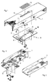
- the intermediate component shown in Fig. 1 consists of a U-shaped section steel with a recess 10 which is designed as an elongated hole.
- the web of the U-profile represents the molded part floor and lies against the surface of the reinforced concrete component.
- Two threaded collar bolts 4 are welded to the base of the molded part and have the two elongated holes 8 perpendicular to the longitudinal extension of the molded part.
- the distance between the threaded collar bolts is identical to the distance between the elongated holes in the top plate 7 of the steel component 6.
- the elongated holes 8 determine the adjustability in the Y direction, while the length of the elongated hole 10 in the molded part defines the X direction.
- the adjustment range is illustrated by the area 12.
- a clamping part made of U-shaped section steel with bore 5 and elongated hole 11 is shown isometrically. Versions with a second hole 5 at the other end for attaching another, unloaded dowel, as a rotation lock is useful from case to case.
- the clamping part 2 is also of U-shaped cross section and has a height which is predetermined by the clear distance between the base plate 9 and the molded part base.
- the clamping part shown has a bore 5 at only one end, through which the threaded bolt of the dowel extends and allows the molded part to be braced against the reinforced concrete component by means of a nut.
- the clamping part also serves to reinforce the section modulus of the intermediate component and is generally dimensioned such that it can be used to absorb the bending moment in the molded part. Accordingly, the invention also provides an embodiment of the clamping part, in which the clamping part sits on the collar of the threaded collar bolts 4 and extends away. The length of the clamping part is matched to the length of the molded part.
- the invention preferably provides hot-rolled profiles in combination with cold-formed parts. In specially stored cases, however, cold-formed cross sections can also be advantageous.
- a molded part with base plate 9 and inserted clamping part 2 is shown isometrically.
- the head part of a hanging column is set down.
- the steel component 6 is screwed onto the base plate 9.
- the head plate can also have a hole pattern in the conventional manner with a narrow hole spacing. Accordingly, the base plate must have slots 8 in order to make an adjustment in the Y direction to be able to take.
- the base plate With a corresponding head plate 7, the base plate can be dispensed with, since fastening can be carried out in the elongated hole 11 of the clamping part.
- the example shown in FIG. 1 for an intermediate component according to the invention is preferably provided for steel components, the stress of which is small by a moment or the normal force of which is only slightly eccentric, in the case of the hanging column.
- the example shown in FIG. 3 represents the case of the connection of a steel component with a moment in the connection joint with low normal force.
- the clamping part is also intended to take over a bending stiffening by gripping the steel component like a gusset plate.
- This example in particular shows the variety of use and design of the intermediate component, always following the principle according to the invention, to be a constructive bridge between reinforced concrete and steel component with a minimum of connecting means and to distribute the forces into the concrete.
- the intermediate component according to the invention can be used not only for hanging supports, but also very generally also for support end plates and brackets which release additional transverse forces on the reinforced concrete component.
- the use of the intermediate component according to the invention is, however, limited by the load-bearing capacity of the reinforced concrete component. It would be pointless to dimension the dowels so that the steel component breaks in the event of an overload.
- the concept of the intermediate component according to the invention to transmit the cutting forces with only one dowel is consequently also influenced by the dimensions of the reinforced concrete component, namely its thickness. It goes without saying that in the case of very thin reinforced concrete slabs, the introduction of high cutting forces remains limited due to the absorption capacity of the reinforced concrete component.
- the use of the intermediate component is not only limited to steel components. It is also suitable for metal structures made of aluminum or other materials. Other shapes of the molded and clamping part are also advantageous, especially when the forces acting on the steel component change in direction and position. For example, molded and clamped parts with a circular shape are of greater advantage if necessary. In claim 5, a clamping part with an elongated hole, which has the shape of a circular disc, is therefore protected. As a result, the area of adjustability is also of circular shape.
Landscapes
- Engineering & Computer Science (AREA)
- Architecture (AREA)
- Physics & Mathematics (AREA)
- Electromagnetism (AREA)
- Civil Engineering (AREA)
- Structural Engineering (AREA)
- Joining Of Building Structures In Genera (AREA)
- Bridges Or Land Bridges (AREA)
- Connection Of Plates (AREA)
Abstract
Description
- Die Erfindung betrifft ein justierbares Zwischenbauteil, das zwischen der Kopfplatte eines vorwiegend durch ein statisches Moment und oder durch Normalkräfte beanspruchten Stahlbauteils oder dergl. und dem Stahlbetondecken- oder Wandbauteil angeordnet ist und mittels Dübel festgelegt wird.
- Bei Stahl-Trägern, -Stützen, insbesonders -Hängestielen, werden die Stirn- oder Kopfplatten mit Bohrungen versehen, in einem geringen Abstand wie er bei Schraubverbindungen im Stahlbau allgemein üblich ist. Befestigungsmittel des Stahlbetonbaus sind indessen Verbindungsmittel, die mit den Schrauben des Stahlbaus insofern nicht vergleichbar sind, als sie einen relativ großen Abstand erfordern, wenn ihre Tragfähigkeit im Beton voll ausgenutzt werden soll. Die Festlegung einer Kopfplatte mittels Dübel, deren Lochabstand stahlbaumäßig gewählt wurde, erweist sich insofern als unwirtschaftlich, als beispielsweise zwei Dübel nur mit jener Last belastet werden können, die ein Einzeldübel im Beton ebenso abzutragen vermag. Es sind auch Dübel bekannt, die allein wegen ihres Spreizdrucks ohne eine äußere Belastung einen Mindestabstand nicht unterschreiten dürfen, der größer ist, als der im Stahlbau übliche Lochabstand.
- Eine große Schwierigkeit beim Einbau der Dübel in ein stark bewehrtes Stahlbetonbauteil besteht darin, daß die Kopfplatten ein Lochbild vorgeben und man mit der einen oder anderen Bohrung aber meist auf Bewehrung trifft, wo ein Niederbringen einer für den Dübel geeigneten Bohrung nicht möglich ist. Man muß dann auf diesen Dübel verzichten oder der Bewehrung ausweichen, das heißt den Punkt der Befestigung versetzen. Bei vier und mehr Bohrungen in der Kopfplatte ist trotz Ausweichens mit großer Wahrscheinlichkeit an einer anderen Stelle mit derselben Schwierigkeit wieder zu rechnen.
- Mit dem Ausweichen erhält das Stahlbauteil jedoch nicht die erforderliche Lage. Beispielsweise würden Hängestiele dann nicht mehr in einer Flucht verlaufen. Die einzubauenden Stahlbauteile sind vorgefertigt und können der Bewehrung wegen nicht umgebaut werden. Um den Erfordernissen gerecht zu werden sind konstruktive Elemente erforderlich, die ein ausweichendes Befestigen am Stahlbetonbauteil ermöglichen, ohne die zum Einbau vorgesehenen Stahlbauteile ändern zu müssen.
- Es besteht somit die Aufgabe ein am Stahlbetonbauteil festlegbares Zwischenbauteil so zu gestalten, daß es vorzugsweise nur mit einem zwischen der Bewehrung versetzten Dübel im Beton so befestigt werden kann, daß die in der Anschlußfuge ausmittig wirkende Normalkraft mit möglichst geringer Beanspruchung des Dübels aufgenommen wird, zum Betonbauteil in einer, bedarfsweise in zwei Richtungen justierbar ist, und das anzuschließende Stahlbauteil stahlbaumäßig in der vorgegebenen Lage befestigt werden kann.
- Die Lösung der gestellten Aufgabe besteht in einem justierbaren Zwischenbauteil, bestehend aus einem Form- und Klemmteil mit den im kennzeichnenden Teil des Hauptanspruchs beschriebenen Merkmalen. Das Zwischenbauteil ist biegebeansprucht und bedarf der statischen Bemessung. Es ist jedoch so konzipiert, daß Form- und Klemmteil statisch zusammenwirken, somit als Teil mit doppelter Nutzung besonders wirtschaftlich gelten muß.
- Das zweidimensionale Einrichten, sowohl in X-Richtung durch Verschieben des Zwischenbauteils, als auch in Y-Richtung durch Verschiebung der Kopfplattte zum Zwischenbauteil in dem jeweils erforderlichen Umfang ist die universelle Form des Ausgleichs für ein beliebiges Ausweichen mit der Befestigung in einer Ebene.
- Die Erfindung macht sich die Erkenntnis zunutze, daß die Tragfähigkeit des Dübels in der Druckzone, insbesondere aber auch in der Zugzone, eines Stahlbetonbauteils im wesentlichen durch die Betonfestigkeit des Stahlbetonbauteils und die Einbindetiefe des Dübels bestimmt werden und von der Beanspruchung des Betonbauteils als tragendes Glied einer Baukonstruktion begrenzt wird.
- Eine wirtschaftliche Befestigung, insbesondere in der Zugzone eines Stahlbetonbauteils, läßt sich daher, wie die Erfindung aufzeigt, optimaler durch nur einen Dübel entsprechend größerer Einbindetiefe erzielen. Ein Dübel läßt sich auch bei stärkster Bewehrung so einbauen, daß die erforderliche Last in das Stahlbetonbauteil übertragen wird. Im Vergleich zu zwei oder mehr Befestigungen stellt die Wahl nur eines Dübels größerer Setz tiefe eine wesentliche Verbesserung der Wirtschaftlichkeit dar, wenn man berücksichtigt, daß die oftmals enge Bewehrung des Stahlbetonbauteils die Erstellung eines Bohrlochs nach einem vorgegebenen Lochbild der Kopfplatte verhindert. Unter Berücksichtigung
- des verminderten Arbeitsaufwandes beim Einbau nur eines Dübels, selbst bei größerer Setztiefe,
- der Behinderung durch die Bewehrung und Ausschluß von Fehlbohrungen,
- der Minimierung der Dübelbeanspruchung durch konstruktive Gestaltung des Zwischenbauteils (Optimierung der Länge des Zwischenbauteils)
ist das erfindungsgemäße Zwischenbauteil zwar mit Mehrkosten verbunden, stellt aber dennoch in Summe eine an Sicherheit technischer, konstruktiver, ebenso wie wirtschaftlicher Hinsicht optimierte Lösung, schlechthin eine rationelle Konstruktion für die gestellte Aufgabe dar. Das Zwischenbauteil erfüllt eine Brückenfunktion die für zwei Bauteile aus sehr unterschiedlichen Materialien nämlich, Stahl und Beton, notwendig ist. - Im Folgenden wird das erfindungsgemäße Zwischenbauteil an zwei Ausführungsbeispielen, denen ein Hängestiel mit unterschiedlicher Kopfplatte zu Grunde liegt, mit Hilfe nachfolgender Zeichnungen nähers erläutert. Einzelheiten des Erfindungsgegenstandes und seiner Ausgestaltungsmöglichkeit, wie sie in den Unteransprüchen beschrieben sind, gehen aus den zeichnerisch dargestellten Beispielen dem Prinzip nach hervor. Es zeigt:
- Fig. 1: Das Formteil mit Gewindebundbolzen in isometrischer Darstellung, für kleine Ausmittigkeit der Normalkraft;
- Fig. 2: Die isometrische Darstellung eines Klemmteils;
- Fig. 3: Darstellung des justierbaren Zwischenbauteils mit ineinanderfügbarem Form- und Klemmteil in isometrischer Darstellung am Beispiel eines Hängestiels.
- Das in Fig. 1 dargestellte Zwischenbauteil besteht aus einem U-förmigen Profilstahl mit einer Ausnehmung 10, die als Langloch ausgebildet ist. Der Steg des U-Profils stellt den Formteilboden dar und liegt an der Oberfläche des Stahlbetonbauteils an. Am Formteilboden sind zwei Gewindebundbolzen 4 angeschweißt, die senkrecht zur Längserstreckung des Formteils die beiden Langlöcher 8 besitzen. Der Abstand der Gewindebundbolzen ist identisch mit dem Abstand der Langlöcher in der Kopfplatte 7 des Stahlbauteils 6. Die Langlöcher 8 bestimmen die Justierbarkeit in Y-Richtung, während die Länge des Langlochs 10 im Formteil die X-Richtung festlegt. Der Justierbereich ist durch die Fläche 12 verdeutlicht.
- In Fig. 2 ist ein Klemmteil aus U-förmigem Profilstahl mit Bohrung 5 und Langloch 11 isometrisch dargestellt. Ausführungen mit einer zweiten Bohrung 5 am anderen Ende zur Anbringung eines weiteren, unbelasteten Dübels, als Drehsicherung ist von Fall zu Fall zweckmäßig.
- Das Klemmteil 2 ist ebenfalls von U-förmigen Querschnitt und besitzt eine Höhe, die durch den lichten Abstand der Grundplatte 9 zum Formteilboden vorgegeben ist. Das dargestellte Klemmteil weist nur an einem Ende eine Bohrung 5 auf, durch welche der Gewindebolzen des Dübels hindurchgreift und mittels einer Mutter ein Verspannen des Formteils gegen das Stahlbetonbauteil ermöglicht.
- Das Klemmteil dient auch zur Verstärkung des Widerstandsmomentes des Zwischenbauteils und wird in der Regel so dimensioniert, daß es zur Aufnahme des Biegemoments im Formteil mit herangezogen werden kann. Dementsprechend sieht die Erfindung auch eine Ausführung des Klemmteils vor, bei welcher das Klemmteil auf dem Bund der Gewindebundbolzen 4 aufsitzt und hinwegreicht. Die Länge des Klemmteils ist auf die Länge des Formteils abgestimmt.
- Auch andere Ausführungen zur Versteifung des biegebeanspruchten Formteils als dargestellt sind von Fall zu Fall vorteilhaft. So können sich vornehmlich solche Querschnitte mit einem hohen Widerstandsmoment als nützlicher erweisen. Insofern sieht die Erfindung vorzugsweise warmgewalzte Profile vor in Kombination mit kaltumgeformten Teilen. In besonders gelagerten Fällen können aber auch kaltgeformte Querschnitte vorteilhaft sein.
- In Fig. 3 ist ein Formteil mit Grundplatte 9 und eingeschobenem Klemmteil 2 isometrisch dargestellt. Nach unten abgesetzt ist das Kopfteil einer Hängesäule. Das Stahlbauteil 6 wird an die Grundplatte 9 angeschraubt. Dabei kann die Kopfplatte auch in der herkömmlichen Weise ein Lochbild besitzen mit engem Bohrungsabstand. Dementsprechend muß die Grundplatte Langlöcher 8 erhalten, um eine Justierung auch in Y-Richtung vor nehmen zu können. Bei entsprechender Kopfplatte 7 kann auf die Grundplatte verzichtet werden, da im Langloch 11 des Klemmteils eine Befestigung vorgenommen werden kann.
- Das in Fig. 1 dargestellte Beispiel für ein erfindungsgemäßes Zwischenbauteil ist vorzugsweise für Stahlbauteile vorgesehen, deren Beanspruchung durch ein Moment gering ist bzw. deren Normalkraft nur eine geringe Ausmittigkeit besitzt, - Fall der Hängesäule. Hingegen representiert das in Fig. 3 dargestellte Beispiel den Fall des Anschlußes eines Stahlbauteils mit einem Moment in der Anschlußfuge mit geringer Normalkraft.
- Bei einem derartigen Zwischenbauteil, wie etwa bei Konsolen mit zusätzlicher Querkraft, wird man bestrebt sein das Formteil lang auszulegen und die Dübel so anzuordnen, daß die Beanspruchung auf Zug minimiert wird und dann von einem Dübel übertragen werden kann, während die Querkraft von einem schubsteifen Element oder Dübel aufgenommen wird und so angeordnet ist, daß er keine Normalkraft erhält. Hierbei ist das Klemmteil auch dafür vorgesehen eine Biegeaussteifung mit zu übernehmen, indem es knotenblechähnlich das Stahlbauteil erfaßt.
- Gerade an diesem Beispiel wird deutlich welche Vielfalt der Nutzung und Ausgestaltung dem Zwischenbauteil zukommt, immer dem erfindungsgemäßen Prinzip folgend, mit einem Minimum an Verbindungsmittel eine konstruktive Brücke zwischen Stahlbeton und Stahlbauteil zu sein und die Kräfte in den Beton verteilend einzuleiten.
- Wie aus den angeführten Beispielen ersichtlich, ist das erfindungsgemäße Zwischenbauteil nicht nur für Hängestiele anwendbar, sondern ebenso ganz allgemein auch für Trägerstirnplatten und Konsolen, die zusätzliche Querkräfte auf das Stahlbetonbauteil abgeben. Die Verwendung des erfindungsgemäßen Zwischenbauteils ist allerdings begrenzt durch die Last-Aufnahmefähigkeit des Stahlbetonbauteils. Es wäre sinnlos die Dübel so zu dimensionieren, daß im Überlastungsfall das Stahlbauteil zu Bruch geht. Das Konzept des erfindungsgemäßen Zwischenbauteils mit nur einem Dübel die Schnittkräfte zu übertragen, wird demzufolge auch von den Abmessungen des Stahlbetonbauteils, namentlich dessen Dicke, beeinflußt. Es versteht sich von selbst, daß bei sehr dünnen Stahlbetonplatten die Einleitung von hohen Schnittkräften durch die Aufnahmefähigkeit des Stahlbetonbauteils begrenzt bleibt.
- Die Anwendung des Zwischenbauteils ist nicht nur auf Stahlbauteile begrenzt. Es eignet sich auch für Metallkonstruktionen aus Aluminium oder aus anderen Werkstoffen. Auch andere Formen des Form- und Klemmteils sind von Vorteil, namentlich dann, wenn die auf das Stahlbauteil einwirkenden Kräfte in Richtung und Lage wechseln. So sind Form- und Klemmteile von kreisförmiger Gestalt im Bedarfsfall von größerem Vorteil. Im Anspruch 5 wird daher auch ein Klemmteil mit Langloch, das die Form einer kreisrunden Scheibe besitzt unter Schutz gestellt. Dadurch ist der Bereich der Justierbarkeit auch von kreisrunder Form.
- Die große Vielfalt der Gestaltung ist mit den angeführten Beispielen nur angedeutet. Vielfache Ausgestaltungen sind im Einzelfall möglich und durch das unter Schutz gestellte Prinzip der Erfindung abgedeckt.
-
- 1 Formteil
- 2 Klemmteil
- 3 Dübelgewindebolzen
- 4 Gewindebundbolzen
- 5 Bohrung
- 6 Stahlbauteil
- 7 Kopfplatte
- 8 Langloch in der Kopfplatte
- 9 Grundplatte
- 10 Ausnehmung
- 11 Langloch im Klemmteil
- 12 Justierbereich für die Achse z des Stahlbauteils x,y,z Raumachsen
Claims (5)
- daß das Zwischenbauteil aus einem Formteil (1) besteht mit einer Ausnehmung (10) auf dem dem Beton zugewandten Formteilboden, durch welche der Dübelgewindebolzen (3) eines im Stahlbeton nach Maßgabe der eingelegten Betonbewehrung einzubauenden Dübels hindurchgreift und im Stahlbetonbauteil festgelegt ist,
- daß das Formteil dadurch einjustierbar ist, daß die Ausnehmung als Langloch ausgbildet ist und durch eine auf den Dübel-Gewindebolzen (3) aufgeschraubte Mutter festlegbar ist,
- daß das Formteil bedarfsweise durch ein biegesteifes Klemmteil (2) verstärkt und gegen das Betonbauteil verspannbar ist, indem der Dübel-Gewindebolzen die Bohrung (5) durchdringt und mit einer zweiten Mutter angezogen wird,
- daß für die Verbindung zum Betonbauteil vorzugsweise nur ein Dübel Verwendung findet,
- daß die Beanspruchung des Dübels dadurch minimiert wird, daß der Dübel mit der Ausmittigkeit, die sich aus dem Quotienten aus Moment und Normalkraft ergibt, zum Stahlbauteil angeordnet ist,
- daß das Formteil eine Grundplatte (9) oder wahlweise Gewindebundbolzen (4) aufweist,
- daß das maßgenaue Einrichten der Kopfplatte (7) in orthogonaler Richtung zur Längserstreckung des Zwischenbauteils dadurch ausführbar ist, daß Langlöcher (8) in der Kopfplatte oder an der Grundplatte (9) des Zwischenbauteils vorgesehen sind.
Applications Claiming Priority (2)
| Application Number | Priority Date | Filing Date | Title |
|---|---|---|---|
| DE3842229 | 1988-12-15 | ||
| DE19883842229 DE3842229C2 (de) | 1988-12-15 | 1988-12-15 | Befestigungsvorrichtung für einen an einer Stahlbetondecke festgelegten Hängestiel |
Publications (2)
| Publication Number | Publication Date |
|---|---|
| EP0378808A2 true EP0378808A2 (de) | 1990-07-25 |
| EP0378808A3 EP0378808A3 (de) | 1992-03-04 |
Family
ID=6369234
Family Applications (1)
| Application Number | Title | Priority Date | Filing Date |
|---|---|---|---|
| EP19890123041 Withdrawn EP0378808A3 (de) | 1988-12-15 | 1989-12-13 | Justierbares Kopfplatten-Zwischenbauteil |
Country Status (3)
| Country | Link |
|---|---|
| EP (1) | EP0378808A3 (de) |
| DD (1) | DD290925A5 (de) |
| DE (1) | DE3842229C2 (de) |
Cited By (3)
| Publication number | Priority date | Publication date | Assignee | Title |
|---|---|---|---|---|
| AU633223B2 (en) * | 1990-08-28 | 1993-01-21 | Sivewright, Gordon Richard | Joint |
| US7166991B2 (en) | 2004-09-14 | 2007-01-23 | Dialog Semiconductor Gmbh | Adaptive biasing concept for current mode voltage regulators |
| CN117702909A (zh) * | 2024-02-04 | 2024-03-15 | 中交西南城市开发有限公司 | 一种钢结构房屋建筑拼装连接部件及拼接方法 |
Families Citing this family (1)
| Publication number | Priority date | Publication date | Assignee | Title |
|---|---|---|---|---|
| DE20016889U1 (de) * | 2000-09-29 | 2000-12-21 | Schwarz Verbindungs Sys Gmbh | In X/Y-Richtung justierbare Platten-Einheit für lösbar durch Feder-Clips anzubringende Wandverkleidungselemente o.dgl. |
Citations (3)
| Publication number | Priority date | Publication date | Assignee | Title |
|---|---|---|---|---|
| DE2644040A1 (de) * | 1976-09-30 | 1978-04-06 | Joseph Americus Slowbe | Winkelverbindung fuer bauteile, insbesondere fuer profilleisten, profiltraeger u.dgl. |
| GB2127516A (en) * | 1982-09-21 | 1984-04-11 | Linton Systems Ltd | Framework bracket |
| DE8707863U1 (de) * | 1987-06-03 | 1987-07-30 | Dig Deutsche Innenbau Gmbh, 4330 Muelheim, De |
Family Cites Families (2)
| Publication number | Priority date | Publication date | Assignee | Title |
|---|---|---|---|---|
| FR1169752A (fr) * | 1957-03-18 | 1959-01-06 | Procédé et dispositif d'ancrage d'éléments de construction dans le béton | |
| DE3231685A1 (de) * | 1982-08-26 | 1984-03-01 | Rieth & Co GmbH, 2000 Hamburg | Einstellbare befestigungsvorrichtung fuer tragkonstruktionen |
-
1988
- 1988-12-15 DE DE19883842229 patent/DE3842229C2/de not_active Expired - Fee Related
-
1989
- 1989-12-13 EP EP19890123041 patent/EP0378808A3/de not_active Withdrawn
- 1989-12-15 DD DD33573889A patent/DD290925A5/de not_active IP Right Cessation
Patent Citations (3)
| Publication number | Priority date | Publication date | Assignee | Title |
|---|---|---|---|---|
| DE2644040A1 (de) * | 1976-09-30 | 1978-04-06 | Joseph Americus Slowbe | Winkelverbindung fuer bauteile, insbesondere fuer profilleisten, profiltraeger u.dgl. |
| GB2127516A (en) * | 1982-09-21 | 1984-04-11 | Linton Systems Ltd | Framework bracket |
| DE8707863U1 (de) * | 1987-06-03 | 1987-07-30 | Dig Deutsche Innenbau Gmbh, 4330 Muelheim, De |
Cited By (4)
| Publication number | Priority date | Publication date | Assignee | Title |
|---|---|---|---|---|
| AU633223B2 (en) * | 1990-08-28 | 1993-01-21 | Sivewright, Gordon Richard | Joint |
| US7166991B2 (en) | 2004-09-14 | 2007-01-23 | Dialog Semiconductor Gmbh | Adaptive biasing concept for current mode voltage regulators |
| CN117702909A (zh) * | 2024-02-04 | 2024-03-15 | 中交西南城市开发有限公司 | 一种钢结构房屋建筑拼装连接部件及拼接方法 |
| CN117702909B (zh) * | 2024-02-04 | 2024-04-19 | 中交西南城市开发有限公司 | 一种钢结构房屋建筑拼装连接部件及拼接方法 |
Also Published As
| Publication number | Publication date |
|---|---|
| DE3842229C2 (de) | 1995-09-07 |
| DD290925A5 (de) | 1991-06-13 |
| DE3842229A1 (de) | 1989-06-01 |
| EP0378808A3 (de) | 1992-03-04 |
Similar Documents
| Publication | Publication Date | Title |
|---|---|---|
| EP0154157A2 (de) | Ankerschiene | |
| EP0275879B1 (de) | In einem Bohrloch eines Befestigungsgrundes einzumörtelnder Halte-und Traganker | |
| WO2014044730A1 (de) | Ankerschienenanordnung | |
| EP1216332B1 (de) | Verbindungssystem zum festen verbinden von mindestens zwei elementen | |
| EP0378808A2 (de) | Justierbares Kopfplatten-Zwischenbauteil | |
| DE19514685C2 (de) | Anordnung von mehreren Pfahlschuhen | |
| EP1932978B1 (de) | Bewehrungselement für die Aufnahme von Kräften in betonierten Platten im Bereich von Stützelementen | |
| DE2606940A1 (de) | Befestigungsmittel | |
| DE2732183C3 (de) | Verbindung zweier mit ihren Stirnflächen einander gegenüberliegenden Stahlbetonteile | |
| EP3819431A1 (de) | Verstärkungsvorrichtung für ein bestandsbauwerk, verstärkungsanordnung mit einem bestandsbauwerk und einer daran angebrachten derartigen verstärkungsvorrichtung sowie verfahren zum verstärken eines derartigen bestandbauwerkes | |
| EP3839162B1 (de) | Thermisch isolierendes bauelement zum einsatz in einer trennfuge zwischen zwei bauwerksteilen | |
| AT522359B1 (de) | Verbindungsvorrichtung zum kraftschlüssigen Verbinden wenigstens zweier Betonfertigteile | |
| EP0493681B1 (de) | Vorrichtung zum Verankern von Wandplatten an einem Verankerungsgrund | |
| DE102012211638A1 (de) | Verankerungssystem | |
| DE19827670B4 (de) | Tragglied aus Naturstein und damit hergestellte Balkone | |
| WO2024081980A1 (de) | Verfahren und schalungssystem zum herstellen einer betonwand | |
| DE2903922C2 (de) | Vorrichtung zum lösbaren Verbinden von Trägern | |
| DE3821683A1 (de) | Verankerungsvorrichtung zur befestigung an mineralischen leichtbaustoffen | |
| DE3000154A1 (de) | Vorrichtung und verfahren zur eintragung von lasten in bestehende stahl- und spannbetonbauteile | |
| EP4299861A1 (de) | Anordnung und verfahren zum nachträglichen verstärken eines bauteils mit mindestens einem diskontinuitätsbereich | |
| DE102022214180A1 (de) | Bauhilfsmittel und Einstellverfahren | |
| EP4357554A1 (de) | Verfahren und schalungssystem zum herstellen einer betonwand | |
| EP4330482A1 (de) | Ankerschiene | |
| DE10161426A1 (de) | Verankerung für verspannte Konstruktionen | |
| DE3700743C2 (de) |
Legal Events
| Date | Code | Title | Description |
|---|---|---|---|
| PUAI | Public reference made under article 153(3) epc to a published international application that has entered the european phase |
Free format text: ORIGINAL CODE: 0009012 |
|
| 17P | Request for examination filed |
Effective date: 19900111 |
|
| AK | Designated contracting states |
Kind code of ref document: A2 Designated state(s): AT BE CH DE FR GB IT LI NL |
|
| RIN1 | Information on inventor provided before grant (corrected) |
Inventor name: HAMPEL, OTTO |
|
| RAP1 | Party data changed (applicant data changed or rights of an application transferred) |
Owner name: STEFAN, WOLFGANG |
|
| PUAL | Search report despatched |
Free format text: ORIGINAL CODE: 0009013 |
|
| AK | Designated contracting states |
Kind code of ref document: A3 Designated state(s): AT BE CH DE FR GB IT LI NL |
|
| 17Q | First examination report despatched |
Effective date: 19921201 |
|
| STAA | Information on the status of an ep patent application or granted ep patent |
Free format text: STATUS: THE APPLICATION IS DEEMED TO BE WITHDRAWN |
|
| 18D | Application deemed to be withdrawn |
Effective date: 19950701 |