EP0376405B1 - Vorrichtung zum Positionieren von Reifenwülsten - Google Patents
Vorrichtung zum Positionieren von Reifenwülsten Download PDFInfo
- Publication number
- EP0376405B1 EP0376405B1 EP89203322A EP89203322A EP0376405B1 EP 0376405 B1 EP0376405 B1 EP 0376405B1 EP 89203322 A EP89203322 A EP 89203322A EP 89203322 A EP89203322 A EP 89203322A EP 0376405 B1 EP0376405 B1 EP 0376405B1
- Authority
- EP
- European Patent Office
- Prior art keywords
- beads
- building drum
- positioning
- bead
- positioning units
- Prior art date
- Legal status (The legal status is an assumption and is not a legal conclusion. Google has not performed a legal analysis and makes no representation as to the accuracy of the status listed.)
- Expired - Lifetime
Links
- 239000011324 bead Substances 0.000 title claims abstract description 78
- 239000000969 carrier Substances 0.000 claims description 13
- 238000004519 manufacturing process Methods 0.000 description 8
- 238000006073 displacement reaction Methods 0.000 description 6
- 230000007246 mechanism Effects 0.000 description 6
- 229910000831 Steel Inorganic materials 0.000 description 3
- 239000010959 steel Substances 0.000 description 3
- 238000010276 construction Methods 0.000 description 1
- 230000002349 favourable effect Effects 0.000 description 1
Images

Classifications
-
- B—PERFORMING OPERATIONS; TRANSPORTING
- B29—WORKING OF PLASTICS; WORKING OF SUBSTANCES IN A PLASTIC STATE IN GENERAL
- B29D—PRODUCING PARTICULAR ARTICLES FROM PLASTICS OR FROM SUBSTANCES IN A PLASTIC STATE
- B29D30/00—Producing pneumatic or solid tyres or parts thereof
- B29D30/06—Pneumatic tyres or parts thereof (e.g. produced by casting, moulding, compression moulding, injection moulding, centrifugal casting)
- B29D30/08—Building tyres
- B29D30/20—Building tyres by the flat-tyre method, i.e. building on cylindrical drums
- B29D30/32—Fitting the bead-rings or bead-cores; Folding the textile layers around the rings or cores
- B29D2030/3207—Positioning the beads
Definitions
- the invention relates to an apparatus for positioning two beads on a building drum for a pneumatic tire, comprising a loading device, two positioning units and a transfer track, said loading device being provided for receiving the beads and for subsequently moving the beads to the positioning units, as well as for substantially simultaneously loading the beads onto said positioning units, said positioning units being provided for transferring the beads coaxially to the building drum along the transfer track to a correct position with respect to a package of liner and carcass plies on the building drum, and for subsequently releasing the beads onto said package.
- a package of belt plies and tread is arranged on a belt drum and subsequently transferred by a transfer ring along a transfer track to a carcass drum, on which previously a package of innerliner and carcass plies has been arranged.
- beads should be positioned in the correct positions and concentrically around said package, after which the pneumatic tire will be completed by further operations.
- a frame comprises two posts.
- a building drum is supported by one post and an arm is rotatably supported by the other post.
- the rotatable arm comprises a loading device on each of its ends and is in normal position coaxial with the building drum.
- the known apparatus furthermore comprises positioning units for taking beads from the loading device closest to the building drum and transferring the beads coaxially to the building drum to a correct position on the building drum.
- Another object of the present invention is an apparatus with which the positioning of the beads takes place substantially mechanically, because of which not only the operator's time is saved, but also the beads are mechanically positioned in the correct positions, so that incorrect manipulations and judgements of the operator are avoided.
- the operator will be able to carry out other manipulations during the operation of the invented apparatus, as e.g. at the belt drum or the carcass drum on behalf of the manufacture of the next pneumatic tire.
- the beads are positioned at the right moment in the building scheme for pneumatic tires, resulting in that unnecessarily waiting is avoided, with increased output of the entire machinery for the manufacture of pneumatic tires as a result.
- the beads are positioned into a more accurate coaxial position to the center line of the building drum, which is favourable for the quality of the pneumatic tire.
- Another advantage of the invented apparatus is that it comprises quickly exchangeable parts, so that the apparatus can be quickly provided with similar parts but of different diameter in order to be ready for manufacturing a different size of pneumatic tire.
- an apparatus of the kind mentioned in the opening paragraph is in accordance with the present invention characterized in that the loading device comprises a pivotable jib on which two carriers for carrying the beads are mounted, said carriers being resiliently displaceable with respect to the jib, from a receiving position to a loading position, said jib being pivotable to a position in which the center line of the bead carried by the carrier coincides with that of the positioning units, and in that each of the two positioning units comprises two pivotable arms each mounted on a respective lever, said arms defining in their mutually closed positions a complete circle of which the center point is on the center line of the building drum, said arms being pivotable away from said closed position and back again by means of drive means, each arm comprising magnets for carrying a bead.
- each of the two positioning units can be provided with two arms that in their mutually closed positions define a portion of a circle of which the center point is on the center line of the building drum, said arms being pivotable away from said closed position and back again by means of drive motors, each arm comprising magnets for carrying a bead.
- a preferred embodiment of the invention is characterized in that each of the two positioning units comprises a carriage movably supported on the transfer track, said track extending parallel to the center line of the building drum, and in that drive motors with electronic control equipment are present for moving each positioning unit to its correct position.
- the above-stated bead is understood to comprise an annular bundle of steel wires and a filling strip of rubber, if mounted on said bundle.
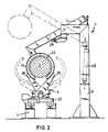
- FIG. 1 shows a schematic side-view of a device for building a pneumatic tire.
- a transfer track 1 extends between a belt building unit (not shown) at the left end of the transfer track shown in figure 1, and a carcass building unit (not shown completely) at the right end of the transfer track shown in figure 1.
- a package of belt plies is arranged on the belt building unit and subsequently provided with a tread, after which all this is transferred by a transfer unit (not shown) along the transfer track 1 to, and positioned around, a previously arranged package of inside liner plies and carcass plies with beads located around said package, the latter being arranged on the carcass drum.
- said belt building unit, said transfer unit and said carcass building unit are generally known, they will not be discussed in this description or shown in the drawings.
- each of said beads is composed of an annular bundle of steel bead wires and, if desired, of a filling strip of rubber, mounted on said bundle.
- a bead is known, it will not be further discussed here and it will not be further shown in the drawings.
- the invention relates to a loading device 3 and a left positioning unit 4 plus a right positioning unit 5, of which an embodiment, shown in the drawing, will be discussed below.
- the invented loading device 3 comprises a leg 6 with a jib 7 pivotably mounted thereon.
- a left carrier 8 and a right carrier 9 are each mounted on one of both sides of the jib 7.
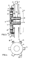
- both carriers are each other's mirror immage, only the left carrier, as shown in cross-section in figure 3, will be discussed here.
- Two carrier pins 10 and 11 are mounted on the jib 7, and, if desired, may be rotatable in bearings.
- a carrier element 12 is disposed on and movably to the right along the carrier pins, a spring 13 pushing said carrier element to the left with respect to the jib 7.
- the carrier element 12 comprises centering cams 14, the number of which can be adapted to e.g. the diameter of the bead, although figure 4 shows six centering cams.
- the combination of carrier element 12 and centering cams is easily and quickly adaptable to a different diameter of the bead.
- Each of the two most elevated centering cams, shown in figure 4 is provided with a hook 15, which is pivotable to a more horizontal position from the position shown in figure 3. Between each of the two hooks and the adjacent inclined end 16 of the cam 14 in question, a bead 17 can be hanged by hand.
- each centering cam 14 comprises a pushing pin 18 which is biassed inwards by a spring 19 to its retracted position shown in figure 3.
- a control member 21 can be moved to the left by for instance a cylinder-piston unit 20 as shown in figure 3, resulting in that the hook 15 is pivoted to its horizontal position, opposing the force of a spring 30, and resulting in that the pushing pin 18 is also pushed to the left.
- the hook 15, being pivoted in its horizontal position clears the way for the bead 17 during its being pushed to the left by the pushing pin 18.
- the invented positioning units 4 and 5 form each other's mirror immage, so that a discussion of positioning unit 4 will be sufficient.
- the positioning unit comprises a carriage 22, which is movable along the transfer track 1, by a motor. Said motor is controlled by electronic control equipment, and causes rotation of a screw spindle. A nut mounted on said carriage engages the screw spindle.
- the motor and the control equipment can easily be designed by an expert and they can be known per se, so that a further discussion is superfluous here.
- each positioning unit 4 or 5 comprises two arms 23 and 24 which in their mutually closed positions, anyway at their inside, define at least the greater portion of a circle.
- Each arm 23, 24 is mounted on its own lever 25, 26, respectively, both levers being pivotably mounted on said carriage 22.
- the arms 23 and 24 are pivotable to the open positions, shown by dotted lines in figure 2, and back again to their mutually closed positions by drive means, which are known per se and therefore not shown, such as a piston-cylinder unit or a nut on a screw spindle, rotatable by a motor for each arm.
- Each arm 23, 24 carries magnets (not shown) for engaging a bead.
- the height of the arms is adjustable with respect to the carriage 22, so that the center line of the arms, in their mutually closed positions, coincides with the center line of the building drum 2.
- Said operator takes two beads from a stock and hangs a bead onto each carrier 8, 9, respectively, as shown in figure 3, after which the bead 17 is stopped from dropping from the said carrier by hooks 15 in their upwardly pivoted position shown in figure 3.
- the inclined edge 16 on each of the centering cams 14 of the carrier 8, 9 respectively, facilitates the concentric positioning of the bead on the carrier 8 according to figure 3.
- the jib 7 is pivoted by the drive motor 28 from the position shown by dotted lines in figure 2, to the position shown by full lines according to figure 1 and 2, i.e. to the position in which the center lines of the carriers 8 and 9 are positioned coaxially to the center line of the building drum 2 as shown in figure 1.
- the leg 6 is provided with an adjustable buffer 29.
- the above-mentioned drive motor 28 can be a cylinder-piston unit, but also a different kind of motor is possible.
- the motor 28 is controllable by an electronic control equipment which can easily be designed by an expert and therefore will not be discussed any further here.
- the two positioning units 4 and 5 are moved from the (not shown) positions at the left and the right of the loading device 3 into the positions shown by full lines in figure 1, along the transfer track 1 which is partly shown in figure 1. During this movement, the two arms 23 and 24 of each of the two positioning units are pivoted into their mutually closed position, as indicated by full lines in figure 2.
- each of the two arms 23 and 24 of each positioning unit 4 and 5 firmly abuts the bead 17 on each of the carriers 8 and 9 when the positioning units 4 and 5 and the carriers 8 and 9 are in their positions shown by full lines in figure 1, the positioning units are moved to such an extent, that the arms, via the beads, somewhat bias the carriers along the carrying pins 10 and 11 towards the jib 7 counter the force of the spring 13.
- magnets mounted on each of the two arms 23 and 24, are pushed against the bead 17, which by means of its bundle of steel bead wires is engaged by the magnets on the two arms.
- the control members 21 in figure 3 are moved to the left by the cylinder-piston units 20, with as a result that the hook 15 in each of the two most elevated cams 14 (figure 4) is pivoted towards a more horizontal position counter the force of the spring 30, so that the bead 17 is released in order to be transferred away by the positioning unit 4 (5, respectively).
- the pushing pins 18 are moved counter their corresponding springs 19, due to said moving of the control members 21, so that said pushing pins push the bead 17 away from the carrier 8 (9, respectively) towards the arms 23 and 24 of the positioning unit 4 (5, respectively).
- the above-stated also occurs with the carrier 9, since said carrier and the carrier 8 as shown in figure 3 are each other's mirror immage.
- the positioning units 4 and 5, each now carrying a bead 17, are moved away from the carrier 8, 9, respectively, by their above-mentioned electronically controlled displacement mechanisms along the transfer track 1.
- the jib 7 with the carriers 8 and 9 thereon is pivoted by the cylinder-piston unit 28 from the position shown by full lines in figure 2, to the position indicated by dotted lines.
- the positioning units 4 and 5 are transferred by their displacement mechanisms along the transfer track 1 to their positions shown by dotted lines in the middle of figure 1, in which the arms 23 and 24, being in their positions shown by full lines in figure 2, coaxially extend around the building drum 2.
- the displacement mechanisms are preferably controlled by electronic controllers, so that each positioning unit carrying its bead is moved to the correct axial position with respect to the package of liner and carcass plies positioned on the building drum 2.
- Displacement mechanisms, controlled by electronic controllers are known per se from the many applications in the art, and therefore they are not further discussed and drawn here.
- each positioning unit is pivoted from the position shown by full lines in figure 2 towards the position indicated by dotted lines, leaving the beads behind, and said beads, together with the plies on the building drum, will be processed further in the usual way, so as to create a pneumatic tire.
- Units on the carriage 22 for pivoting the arms 23 and 24 are already discussed herein.
- the positioning units 4 and 5 are transferred by the discussed displacement mechanisms along the transfer track 1, into the positions indicated by dotted lines at the right in figure 1.
- the beads, tread and carcass plies, positioned on the building drum are available for a further processing into a pneumatic tire.
- the positioning units 4 and 5 are transferred by said discussed displacement mechanisms to the positions indicated by full lines at the left in figure 1, so that the above-described working cycle can be executed again from its beginning for the manufacture of a next pneumatic tire.
Landscapes
- Engineering & Computer Science (AREA)
- Mechanical Engineering (AREA)
- Tyre Moulding (AREA)
Claims (8)
- Vorrichtung zum Positionieren von zwei Reifenwülsten (17) auf einer Konfektioniertrommel (2) mit einer Ladeeinrichtung (3), zwei Positioniereinheiten (4, 5) und einer Transportbahn (1), wobei die Ladeeinrichtung (3) die Wülste (17) aufnimmt und sie danach zu den Positioniereinheiten (4, 5) befördert und im wesentlichen gleichzeitig die Wülste (17) auf den Positioniereinheiten (4, 5) lädt, welche Positioniereinheiten (4, 5) die Wülste (17) koaxial zur Konfektioniertrommel (2) auf der Transportbahn (1) korrekt zu einem Paket von Futter- und Karkassenlagen auf der Konfektioniertrommel (2) transportieren und anschließend die Wülste (17) auf dem Paket freigeben, dadurch gekennzeichnet, daß die Ladeeinrichtung (3) einen schwenkbaren Ausleger (7) umfaßt, auf dem zwei Halterungen (8, 9) befestigt sind, die zum Ausleger (7) federnd aus einer Aufnahmeposition in eine Ladeposition verschoben werden können, und der in eine Position geschwenkt werden kann, in der die Mittellinie der Wulst (17), die durch die Halterung (8, 9) gehalten wird, mit der Mittellinie der Positioniereinheiten (4, 5) übereinstimmt, und dadurch, daß die beiden Positioniereinheiten (4, 5) je zwei schwenkbare Arme (23, 24) umfassen, die jeweils auf einem dazugehörigen Hebel (25, 26) befestigt sind, wobei die Arme (23, 24) in der zueinander geschlossenen Position einen vollen Kreis begrenzen, dessen Mittelpunkt auf der Mittellinie der Konfektioniertrommel (2) liegt, sie durch Antriebsvorrichtungen aus der geschlossenen Position heraus- und wieder in sie zurückgeschwenkt werden können und jeder Arm (23, 24) Magnete zum Halten einer Wulst (17) aufweist.
- Vorrichtung nach Anspruch 1, dadurch gekennzeichnet, daß die Ladeeinrichtung (3) versehen ist mit einem Schenkel (6) zum Halten des Auslegers (7), einer Antriebsvorrichtung (28) und einem einstellbaren Puffer (29) zum Schwenken des Auslegers (7) in eine durch den Puffer (29) einstellbare Position, in der die Mittellinie der Wulst (17) in der Halterung (8, 9) mit der Mittellinie der Konfektioniertrommel (2) übereinstimmt.
- Vorrichtung nach Anspruch 1 oder 2, dadurch gekennzeichnet, daß jede der beiden Positioniereinheiten (4, 5) einen Schlitten (22) umfaßt, der beweglich auf der Transportbahn (1) angebracht ist, wobei die Bahn (1) parallel zur Mittellinie der Konfektioniertrommel (2) verläuft, und daß Antriebsmotoren mit elektronischer Steuerung zum Bewegen jeder Positioniereinheit (4, 5) gegenüber der Konfektioniertrommel (2) vorhanden sind.
- Vorrichtung nach Anspruch 1, dadurch gekennzeichnet, daß die beiden Arme (23, 24) auf jeder Positioniereinheit (4, 5) durch Arme mit einem anderen Bogenradius ausgetauscht werden können.
- Vorrichtung nach einem der vorangegangenen Ansprüche, dadurch gekennzeichnet, daß jede Halterung (8, 9) mindestens zwei Haken (15) zum Einhängen von Wülsten in Aufnahmeposition mit Andruckstiften (18) zum Andrücken der Wulst (17) in Richtung und gegen die betreffende Positioniereinheit (4, 5) und einen Antriebsmotor aufweist, der die Haken (15) in eine Position schwenkt, in der die Wulst (17) losgelassen wird, und der gleichzeitig die Andruckstifte (18) mit den Wülsten (17) an die betreffende Positioniereinheit (4, 5) andrückt.
- Vorrichtung nach Anspruch 5, dadurch gekennzeichnet, daß jede Halterung (8, 9) ein Halteelement (12) und eine Reihe von Zentriernocken (14) umfaßt, auf denen die Andruckstifte (18) befestigt sind, wobei mindestens zwei der höchsten Zentriernocken (14) schwenkbare Haken (15) umfassen.
- Vorrichtung nach Anspruch 6, dadurch gekennzeichnet, daß die Zentriernocken (14) so auf dem Halteelement (12) befestigt sind, daß sie durch Zentriernocken (14) einer anderen Größe ausgetauscht werden können, um sie dem Durchmesser der Wulst (17) anzupassen.
- Vorrichtung nach einem der vorangegangenen Ansprüche, dadurch gekennzeichnet, daß nach dem Positionieren der Wülste (17) auf der Konfektioniertrommel (2) von einer Seite ein freier Zugang zur Transportbahn (1) möglich ist, da sich der Ausleger (7) in seiner höchste Position und sich beide Schlitten (22) mit den Halterungen (8, 9) und den Positioniereinheiten (4, 5) an der äußersten Stelle auf der Transportbahn (1) gegenüber dieser Seite befinden.
Priority Applications (1)
| Application Number | Priority Date | Filing Date | Title |
|---|---|---|---|
| AT89203322T ATE97057T1 (de) | 1988-12-27 | 1989-12-22 | Vorrichtung zum positionieren von reifenwuelsten. |
Applications Claiming Priority (2)
| Application Number | Priority Date | Filing Date | Title |
|---|---|---|---|
| NL8803174A NL8803174A (nl) | 1988-12-27 | 1988-12-27 | Inrichting voor het plaatsen van hielringen voor een luchtband. |
| NL8803174 | 1988-12-27 |
Publications (2)
| Publication Number | Publication Date |
|---|---|
| EP0376405A1 EP0376405A1 (de) | 1990-07-04 |
| EP0376405B1 true EP0376405B1 (de) | 1993-11-10 |
Family
ID=19853443
Family Applications (1)
| Application Number | Title | Priority Date | Filing Date |
|---|---|---|---|
| EP89203322A Expired - Lifetime EP0376405B1 (de) | 1988-12-27 | 1989-12-22 | Vorrichtung zum Positionieren von Reifenwülsten |
Country Status (5)
| Country | Link |
|---|---|
| EP (1) | EP0376405B1 (de) |
| AT (1) | ATE97057T1 (de) |
| DE (2) | DE68910659T2 (de) |
| ES (1) | ES2045396T3 (de) |
| NL (1) | NL8803174A (de) |
Families Citing this family (3)
| Publication number | Priority date | Publication date | Assignee | Title |
|---|---|---|---|---|
| WO2003061954A1 (en) * | 2001-12-27 | 2003-07-31 | Gian Luigi Bosio | Tyre building apparatus |
| DE102004032511A1 (de) * | 2004-07-06 | 2006-02-16 | Continental Aktiengesellschaft | Verfahren und Vorrichtung zum Positionieren von Wulstkernen |
| CN103552265A (zh) * | 2013-11-06 | 2014-02-05 | 软控股份有限公司 | 工程胎90度包贴边装置 |
Family Cites Families (6)
| Publication number | Priority date | Publication date | Assignee | Title |
|---|---|---|---|---|
| DE1016924B (de) * | 1953-06-10 | 1957-10-03 | Continental Gummi Werke Ag | Vorrichtung zum Anlegen der Wulstkerne an Reifenaufbaumaschinen |
| DE1180515B (de) * | 1963-01-15 | 1964-10-29 | Continental Gummi Werke Ag | Vorrichtung zum Anlegen der Wulstkerne an Reifenaufbaumaschinen |
| DE1925304A1 (de) * | 1969-05-17 | 1970-11-19 | Continental Gummi Werke Ag | Schwenkvorrichtung fuer Zentrierglocken an Reifenaufbaumaschinen |
| BE786081A (fr) * | 1971-07-13 | 1973-01-10 | Uniroyal Sa | Appareil et procede pour maintenir les tringles des bourrelets de pneu |
| JPS587339A (ja) * | 1981-07-03 | 1983-01-17 | Yokohama Rubber Co Ltd:The | タイヤ成形装置におけるバンド及びビ−ドの移送供給装置 |
| DE3509025A1 (de) * | 1985-03-13 | 1986-09-25 | Vsesojuznyj naučno-issledovatel'skij i konstruktorskij institut po oborudovaniju dlja šinnoj promyšlennosti NIIŠINMAŠ SSSR, Jaroslavl | Einrichtung zur zufuehrung von ringfoermigen reifenteilen zur aufbautrommel |
-
1988
- 1988-12-27 NL NL8803174A patent/NL8803174A/nl not_active Application Discontinuation
-
1989
- 1989-12-22 EP EP89203322A patent/EP0376405B1/de not_active Expired - Lifetime
- 1989-12-22 ES ES89203322T patent/ES2045396T3/es not_active Expired - Lifetime
- 1989-12-22 AT AT89203322T patent/ATE97057T1/de not_active IP Right Cessation
- 1989-12-22 DE DE68910659T patent/DE68910659T2/de not_active Expired - Fee Related
- 1989-12-27 DE DE8915191U patent/DE8915191U1/de not_active Expired - Lifetime
Also Published As
| Publication number | Publication date |
|---|---|
| EP0376405A1 (de) | 1990-07-04 |
| ATE97057T1 (de) | 1993-11-15 |
| DE68910659D1 (de) | 1993-12-16 |
| DE8915191U1 (de) | 1990-03-01 |
| DE68910659T2 (de) | 1994-05-19 |
| NL8803174A (nl) | 1990-07-16 |
| ES2045396T3 (es) | 1994-01-16 |
Similar Documents
| Publication | Publication Date | Title |
|---|---|---|
| US4230517A (en) | Modular tire building machine | |
| EP0039621B1 (de) | Verfahren und Vorrichtung zur Herstellung eines Reifens | |
| US4634489A (en) | Device for transferring a tire carcass band | |
| CS247165B2 (en) | Device for transportation of vehicles' whhels tyres raw casings into curing press | |
| US4197065A (en) | System for feeding raw elastomer products to vulcanizing autoclaves | |
| EP0351222B1 (de) | Verfahren und Vorrichtung zum Aufbauen von Luftreifen | |
| JPH03101906A (ja) | タイヤ加硫機のタイヤ取出し装置 | |
| US3267515A (en) | Tire curing press loader | |
| US3229329A (en) | Tire curing press and loader therefor | |
| US3343208A (en) | Device for removing a pneumatic tire from the curing unit and for postinflating and discharging it | |
| US4452577A (en) | Tire loader | |
| EP0376405B1 (de) | Vorrichtung zum Positionieren von Reifenwülsten | |
| US4726861A (en) | Method and device for automatically centering and feeding beads onto a tire building drum | |
| EP0289469B1 (de) | Reifenvulkanisierpresse mit Vorrichtung zum Laden und Entladen der Reifen | |
| EP0358435B1 (de) | Vorrichtung zur Reifenherstellung mit einer Transfervorrichtung für Reifenelemente. | |
| US3620561A (en) | Transporting device for use in connection with the manufacture of unvulcanized belted tires | |
| US3332820A (en) | Band support | |
| JP2980642B2 (ja) | タイヤヒートプレスにおいてグリーンタイヤの装入および完成タイヤの取出し又はそのいずれかを行なうための装置 | |
| JPS6356057B2 (de) | ||
| JP2724874B2 (ja) | 完成グリーンタイヤの取出し方法及びその装置 | |
| JPS6211668B2 (de) | ||
| JP3219567B2 (ja) | 空気入タイヤ用把持冷却装置 | |
| JPH05131452A (ja) | タイヤ加硫機のタイヤ取出装置 | |
| JPS5922737A (ja) | 生タイヤの保持並びに供給装置 | |
| JPS5983637A (ja) | タイヤ成形機におけるタイヤ取出装置 |
Legal Events
| Date | Code | Title | Description |
|---|---|---|---|
| PUAI | Public reference made under article 153(3) epc to a published international application that has entered the european phase |
Free format text: ORIGINAL CODE: 0009012 |
|
| 17P | Request for examination filed |
Effective date: 19900427 |
|
| AK | Designated contracting states |
Kind code of ref document: A1 Designated state(s): AT BE CH DE ES FR GB GR IT LI LU NL SE |
|
| 17Q | First examination report despatched |
Effective date: 19911204 |
|
| GRAA | (expected) grant |
Free format text: ORIGINAL CODE: 0009210 |
|
| AK | Designated contracting states |
Kind code of ref document: B1 Designated state(s): AT BE CH DE ES FR GB GR IT LI LU NL SE |
|
| PG25 | Lapsed in a contracting state [announced via postgrant information from national office to epo] |
Ref country code: SE Effective date: 19931110 Ref country code: LI Effective date: 19931110 Ref country code: GR Free format text: LAPSE BECAUSE OF FAILURE TO SUBMIT A TRANSLATION OF THE DESCRIPTION OR TO PAY THE FEE WITHIN THE PRESCRIBED TIME-LIMIT Effective date: 19931110 Ref country code: CH Effective date: 19931110 Ref country code: BE Effective date: 19931110 Ref country code: AT Effective date: 19931110 |
|
| REF | Corresponds to: |
Ref document number: 97057 Country of ref document: AT Date of ref document: 19931115 Kind code of ref document: T |
|
| ITF | It: translation for a ep patent filed | ||
| REF | Corresponds to: |
Ref document number: 68910659 Country of ref document: DE Date of ref document: 19931216 |
|
| PG25 | Lapsed in a contracting state [announced via postgrant information from national office to epo] |
Ref country code: LU Free format text: LAPSE BECAUSE OF NON-PAYMENT OF DUE FEES Effective date: 19931231 |
|
| REG | Reference to a national code |
Ref country code: ES Ref legal event code: FG2A Ref document number: 2045396 Country of ref document: ES Kind code of ref document: T3 |
|
| REG | Reference to a national code |
Ref country code: CH Ref legal event code: PL |
|
| ET | Fr: translation filed | ||
| PLBE | No opposition filed within time limit |
Free format text: ORIGINAL CODE: 0009261 |
|
| STAA | Information on the status of an ep patent application or granted ep patent |
Free format text: STATUS: NO OPPOSITION FILED WITHIN TIME LIMIT |
|
| 26N | No opposition filed | ||
| PGFP | Annual fee paid to national office [announced via postgrant information from national office to epo] |
Ref country code: GB Payment date: 19971125 Year of fee payment: 9 |
|
| PGFP | Annual fee paid to national office [announced via postgrant information from national office to epo] |
Ref country code: ES Payment date: 19971212 Year of fee payment: 9 |
|
| PGFP | Annual fee paid to national office [announced via postgrant information from national office to epo] |
Ref country code: FR Payment date: 19971224 Year of fee payment: 9 |
|
| PGFP | Annual fee paid to national office [announced via postgrant information from national office to epo] |
Ref country code: NL Payment date: 19971231 Year of fee payment: 9 |
|
| PGFP | Annual fee paid to national office [announced via postgrant information from national office to epo] |
Ref country code: DE Payment date: 19980128 Year of fee payment: 9 |
|
| PG25 | Lapsed in a contracting state [announced via postgrant information from national office to epo] |
Ref country code: GB Free format text: LAPSE BECAUSE OF NON-PAYMENT OF DUE FEES Effective date: 19981222 |
|
| PG25 | Lapsed in a contracting state [announced via postgrant information from national office to epo] |
Ref country code: NL Free format text: LAPSE BECAUSE OF NON-PAYMENT OF DUE FEES Effective date: 19990701 |
|
| GBPC | Gb: european patent ceased through non-payment of renewal fee |
Effective date: 19981222 |
|
| PG25 | Lapsed in a contracting state [announced via postgrant information from national office to epo] |
Ref country code: FR Free format text: LAPSE BECAUSE OF NON-PAYMENT OF DUE FEES Effective date: 19990831 |
|
| NLV4 | Nl: lapsed or anulled due to non-payment of the annual fee |
Effective date: 19990701 |
|
| REG | Reference to a national code |
Ref country code: FR Ref legal event code: ST |
|
| PG25 | Lapsed in a contracting state [announced via postgrant information from national office to epo] |
Ref country code: DE Free format text: LAPSE BECAUSE OF NON-PAYMENT OF DUE FEES Effective date: 19991001 |
|
| PG25 | Lapsed in a contracting state [announced via postgrant information from national office to epo] |
Ref country code: ES Free format text: LAPSE BECAUSE OF NON-PAYMENT OF DUE FEES Effective date: 19991223 |
|
| REG | Reference to a national code |
Ref country code: ES Ref legal event code: FD2A Effective date: 20000114 |
|
| PG25 | Lapsed in a contracting state [announced via postgrant information from national office to epo] |
Ref country code: IT Free format text: LAPSE BECAUSE OF NON-PAYMENT OF DUE FEES Effective date: 20051222 |