EP0375568A1 - Modulare Zusammenbauvorrichtung für einen mehrpoligen Differentialschutzschalter - Google Patents
Modulare Zusammenbauvorrichtung für einen mehrpoligen Differentialschutzschalter Download PDFInfo
- Publication number
- EP0375568A1 EP0375568A1 EP89420457A EP89420457A EP0375568A1 EP 0375568 A1 EP0375568 A1 EP 0375568A1 EP 89420457 A EP89420457 A EP 89420457A EP 89420457 A EP89420457 A EP 89420457A EP 0375568 A1 EP0375568 A1 EP 0375568A1
- Authority
- EP
- European Patent Office
- Prior art keywords
- circuit breaker
- jumper
- housing
- differential circuit
- differential
- Prior art date
- Legal status (The legal status is an assumption and is not a legal conclusion. Google has not performed a legal analysis and makes no representation as to the accuracy of the status listed.)
- Granted
Links
Images


Classifications
-
- H—ELECTRICITY
- H02—GENERATION; CONVERSION OR DISTRIBUTION OF ELECTRIC POWER
- H02B—BOARDS, SUBSTATIONS OR SWITCHING ARRANGEMENTS FOR THE SUPPLY OR DISTRIBUTION OF ELECTRIC POWER
- H02B1/00—Frameworks, boards, panels, desks, casings; Details of substations or switching arrangements
- H02B1/26—Casings; Parts thereof or accessories therefor
-
- H—ELECTRICITY
- H01—ELECTRIC ELEMENTS
- H01H—ELECTRIC SWITCHES; RELAYS; SELECTORS; EMERGENCY PROTECTIVE DEVICES
- H01H71/00—Details of the protective switches or relays covered by groups H01H73/00 - H01H83/00
- H01H71/02—Housings; Casings; Bases; Mountings
- H01H71/0264—Mountings or coverplates for complete assembled circuit breakers, e.g. snap mounting in panel
- H01H71/0271—Mounting several complete assembled circuit breakers together
-
- H—ELECTRICITY
- H01—ELECTRIC ELEMENTS
- H01H—ELECTRIC SWITCHES; RELAYS; SELECTORS; EMERGENCY PROTECTIVE DEVICES
- H01H71/00—Details of the protective switches or relays covered by groups H01H73/00 - H01H83/00
- H01H71/02—Housings; Casings; Bases; Mountings
- H01H71/0207—Mounting or assembling the different parts of the circuit breaker
- H01H2071/0242—Assembling parts of a circuit breaker by using snap mounting techniques
-
- H—ELECTRICITY
- H01—ELECTRIC ELEMENTS
- H01H—ELECTRIC SWITCHES; RELAYS; SELECTORS; EMERGENCY PROTECTIVE DEVICES
- H01H71/00—Details of the protective switches or relays covered by groups H01H73/00 - H01H83/00
- H01H71/08—Terminals; Connections
- H01H71/082—Connections between juxtaposed circuit breakers
-
- H—ELECTRICITY
- H01—ELECTRIC ELEMENTS
- H01H—ELECTRIC SWITCHES; RELAYS; SELECTORS; EMERGENCY PROTECTIVE DEVICES
- H01H83/00—Protective switches, e.g. circuit-breaking switches, or protective relays operated by abnormal electrical conditions otherwise than solely by excess current
- H01H83/20—Protective switches, e.g. circuit-breaking switches, or protective relays operated by abnormal electrical conditions otherwise than solely by excess current operated by excess current as well as by some other abnormal electrical condition
- H01H83/22—Protective switches, e.g. circuit-breaking switches, or protective relays operated by abnormal electrical conditions otherwise than solely by excess current operated by excess current as well as by some other abnormal electrical condition the other condition being unbalance of two or more currents or voltages
- H01H83/226—Protective switches, e.g. circuit-breaking switches, or protective relays operated by abnormal electrical conditions otherwise than solely by excess current operated by excess current as well as by some other abnormal electrical condition the other condition being unbalance of two or more currents or voltages with differential transformer
-
- H—ELECTRICITY
- H01—ELECTRIC ELEMENTS
- H01H—ELECTRIC SWITCHES; RELAYS; SELECTORS; EMERGENCY PROTECTIVE DEVICES
- H01H9/00—Details of switching devices, not covered by groups H01H1/00 - H01H7/00
- H01H9/02—Bases, casings, or covers
- H01H9/0264—Protective covers for terminals
-
- H—ELECTRICITY
- H02—GENERATION; CONVERSION OR DISTRIBUTION OF ELECTRIC POWER
- H02B—BOARDS, SUBSTATIONS OR SWITCHING ARRANGEMENTS FOR THE SUPPLY OR DISTRIBUTION OF ELECTRIC POWER
- H02B1/00—Frameworks, boards, panels, desks, casings; Details of substations or switching arrangements
- H02B1/015—Boards, panels, desks; Parts thereof or accessories therefor
- H02B1/04—Mounting thereon of switches or of other devices in general, the switch or device having, or being without, casing
- H02B1/041—Mechanical coupling for side-by-side mounted apparatus
-
- H—ELECTRICITY
- H02—GENERATION; CONVERSION OR DISTRIBUTION OF ELECTRIC POWER
- H02B—BOARDS, SUBSTATIONS OR SWITCHING ARRANGEMENTS FOR THE SUPPLY OR DISTRIBUTION OF ELECTRIC POWER
- H02B1/00—Frameworks, boards, panels, desks, casings; Details of substations or switching arrangements
- H02B1/015—Boards, panels, desks; Parts thereof or accessories therefor
- H02B1/06—Boards, panels, desks; Parts thereof or accessories therefor having associated enclosures, e.g. for preventing access to live parts
Definitions
- the invention relates to a multipole differential circuit breaker formed by the modular assembly side by side of a differential trip unit to a circuit breaker unit, which comprises a pair of first and second connection terminals per pole, arranged on the narrow lateral faces. opposite, and a first large lateral abutment face provided with an access light to a trigger bar of a first lever switching mechanism, said trigger block comprising: - a totalizing transformer with secondary winding supplying a trip relay, a second control mechanism controlled by the relay and a lever, and having a trigger finger projecting from an orifice formed in a second large lateral face combined with a molded housing, fixing means for ensuring the assembly of the two blocks after automatic establishment of a first mechanical triggering link resulting from the insertion of the finger in the light during the joining phase of the first and second large lateral faces, - and connecting conductors connecting the primary circuit of the transformer to the second terminals of the circuit breaker block.
- the connecting conductors pass through passages provided in the circuit breaker block, and are connected to the terminals from the inside.
- the object of the invention is to facilitate the adaptation of a differential trip unit with lateral outputs of the connecting conductors, and with external electrical connection to the circuit breaker unit.
- the circuit breaker according to the invention is characterized in that the second large lateral face of the differential trip unit has an opening for crossing the connecting conductors towards the interface between the two units, and that the fixing means comprise an articulated hooking , and a rider from locking, arranged respectively on the side of the first and second opposite terminals, said jumper being maneuverable towards an active position to ensure the positioning of the connecting conductors against the second large lateral face during the gradual approximation of the two blocks.
- the second large side face of the housing is equipped with parallel grooves, in which the connecting conductors are embedded in the active position of the locking jumper. This results in an assembly without transverse play of the two blocks, despite the presence in the interface of the connecting conductors passing through the opening of the second large lateral face of the trip unit. The free ends of the connecting conductors are then engaged from the outside in the second terminals of the circuit breaker block.
- the articulated attachment comprises a lug secured to the housing and intended to fit into a conjugate recess of the circuit breaker block, so as to allow at the start of the assembly phase a relative pivoting of the two blocks around a fictitious vertical axis s 'extending in the direction of the depth.
- a single lug is sufficient to carry out the articulated attachment, which is opposite the second connection terminals of the ends of the connecting conductors to facilitate the electrical connection of the trip unit to the circuit breaker unit.
- the locking jumper is pivotally mounted about an axis in a housing of the trip unit block, and includes a retaining arm capable of engaging in a recess for fixing the circuit breaker block, said arm having a ramp arranged to ensure a cam effect on a step of the recess when the jumper is maneuvered from the inactive position to the active position.
- the locking jumper is equipped with a control lever arranged opposite the articulation axis, and substantially in square to the retaining arm.
- a tamper-evident cover is attached to the second terminals and the jumper to prevent any electrical disconnection and mechanical disassembly of the differential trip unit.
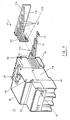
- a bipolar differential circuit breaker 10 is formed by the modular assembly side by side from a differential trip unit 12 to a circuit breaker block 14.
- the two blocks 12,14 with insulated housings 16,18,20 of parallelepiped shape, are interconnected by a first mechanical link 22 for triggering, and a second mechanical link 24 for reset by the levers 26,28.
- Each pole of the circuit breaker block 14 comprises a pair of first and second terminals 30, 32 with connection cages and clamping screws, situated at the level of the opposite narrow side faces 34, 36 of the respective housing 16, 18.
- the base 37 of each housing 16,18,20 is provided with a snap-in profile for mounting on a support rail.
- the first large side face of attachment of the housing 18 includes a curvilinear light 40 authorizing access to the automatic trip bar of the switching mechanism of the circuit breaker block 14.
- Two fixing recesses 42, 44 are arranged at each vertical edge delimiting the large face 38 of the two other narrow side faces 34,36.
- the first large face 38 of the circuit breaker block 14 also has circular orifices 46 for the introduction of spikes 48 combined for centering and polarizing belonging to the differential trip unit 12.
- the trip unit 12 contains a summing transformer 50 having two primary windings 52,54 and a secondary winding 56 wound on an O-ring.
- the secondary winding 56 is electrically connected to a trip relay 58 cooperating with the control mechanism 60 associated with the lever 28.
- the primary windings are connected to a pair of connection terminals 62, housed in the housing 20, on the same side than the second terminals 32 of the circuit breaker block 14.
- One of the edges of the second large lateral face 68 comprises a lug 76 for hooking coming from molding with the housing 20, and intended to fit into the recess 42 conjugated during the modular assembly of the two blocks 12, 14.
- the housing 20 includes a housing 78 for receiving a locking jumper 80.
- the two connecting conductors 72, 74 are shaped as U-shaped half-loops whose free ends 82, 84 are inserted from the outside into the respective cages of the terminals 32 of the circuit breaker block 14. Between the vertical light 70 and the lateral face narrow 86 extend perpendicularly two parallel grooves 88.90, formed in the second large face 68 of the housing 20. Opposite the ends 82.84, the output branches of the conductors 72.74 are embedded in the grooves 88 , 90 respective, so as to avoid any transverse play between the two blocks 12,14 assembled.
- a shutter cover 92 associated with a sealing wire is added after assembly of the blocks 12,14 on the terminals 32 of the circuit breaker block 14 to ensure the inviolability of the device.
- the electrical connection of the differential circuit breaker 10 is made by terminals 30 and 62 connected to the active incoming 94 and outgoing 96 conductors.
- the housing 20 of the differential trip unit 12 is constituted by the snap-fastening of two half-shells 98,100 in the depth direction, that is to say perpendicular to the transverse direction of joining of the two blocks 12,14.
- the half lower shell 100 contains the summing transformer 50, the terminals 62 and the connecting conductors 72, 74.
- the control mechanism 60 and the relay 58 are the control mechanism 60 and the relay 58.
- One 102 of the side walls of the insulating half-shell 98 constitutes at the same time an internal mounting flange for the mechanism 60.
- This flange includes positioning tongues 104, 106 capable of engaging in vertical guiding grooves 108, 110, formed in the lower half-shell 100.
- the base of the jumper 80 comprises an axis 112 of articulation constituted by two cylindrical end pieces 114, 116 arranged at the ends of two elastic branches separated from one another by a median slot 113.
- the entrance to the housing 78 has a slightly frustoconical shape so as to compress the two branches during the fitting of the jumper 80 (FIG. 4).
- the two ends 114,116 expand in a cylindrical bearing provided in the bottom of the housing 78.
- the axis 112 is then locked by snap-fastening in the housing 78, and the jumper 80 can be pivotally actuated around the axis 112 between an inactive position and an active position.
- the jumper 80 comprises a control lever 120 opposite the articulation axis 112, and a retaining arm 122 disposed substantially at right angles to the lever 120.
- the retaining arm 122 is provided with a ramp 124 in the form of a cam intended to cooperate with a step 126 of the housing 18 inside the recess 44.
- FIG. 6 shows the jumper 80 in the inactive position after insertion of the pin 112 in the housing 78 of the housing 20.
- a manual action of lateral clamping of the two blocks 12,14 maintains the large face 68 of the housing 20 against the mating face 38 of abutment of the housing 18.
- FIG. 7 represents the start of the locking operation of the two blocks 12, 14 during which the jumper 80 is driven in rotation anticlockwise, by means of the control lever 120 maneuvered from the outside in the direction of arrow F2. It is noted that in an intermediate position, the reaction of the ramp 124 of the retaining arm 122 on the step 126 causes a cam effect allowing a progressive bringing together of the two blocks 12,14.
- the manual lateral clamping action can be interrupted, followed by the rotation of the jumper 80 towards the active position (FIG. 8) in which the retaining arm 122 ensures positive locking of the two blocks 12,14.
- a boss 130 provided on the retaining arm 122 opposite the ramp 124, cooperates with the housing 18 in the active position to form a hard point opposing the reverse operation of the jumper 80 to the inactive position.
- the introduction of the hooking lug 76 into the conjugate recess 42 forms an articulated coupling or coupling allowing relative pivoting of the two blocks 12,14.
- the pins 48 engage in the orifices 46, and the finger 64 for triggering the control mechanism 60 of the differential trigger block 12 penetrates into the lumen 40 of the face 38 to form the first connection mechanical trigger 22.
- the two ends 82, 84 of the connection conductors 72, 74 are positioned from the outside in the respective cages of the terminals 32. It is noted that the articulation coupling of the lug 76 in the recess 42 is arranged opposite the terminals 32.
- the manual action of lateral tightening of the two blocks takes place, followed by the mechanical locking by the jumper 80, as described previously with reference to FIGS. 6 to 8.
- the bringing together of the two blocks 12, 14 by the rotation of the jumper 80 from the intermediate position (FIG. 7) to the active position (FIG. 8) causes the output branches of the connecting conductors 72,74 to be embedded in the respective grooves 88,90 of the large face 68 of the trip unit 12.
- the depth of the grooves 88.90 corresponds substantially to the diameter of the connecting conductors 72.74, so as to allow perfect adhesion between the two faces 38.68, when the jumper 80 is in the active position ( Figure 8).
- the location or the dimensioning of the pins 48 for centering and coding is a function of the size of the differential trip unit 12. Such security prevents any non-compatible adaptation to the sizes of the two units 12, 14.
- the shutter cover 92 is fitted with a latch 140 (FIG. 2) which can be moved in the direction of the arrow F3 so as to engage in an orifice 142 in the housing 16.
- the latch 140 comprises a tab having a hole 144 for the introduction of the sealing wire. In the case of factory assembly, the latch 140 can be locked without the possibility of disassembly.
- the four-pole differential trip unit 12 has four rigid 72,74,172,174 conductors for the electrical connection with the associated circuit breaker unit (not shown).
- the conductors 72, 74, 172, 174 are protected by an insulator 176 made of plastic material having an L-shaped configuration.
- the shortest branch 177 of the insulator 176 is provided with a tab 178 for hooking intended to snap onto the base of the trip unit 12 in line with the opening 70.
- the other branch 180 is applied to the narrow side faces 36 of the circuit breaker unit to prevent access to the second terminals 32.
- the cover 92 for shutter is then attached from above the branch 180 of the insulator 176 for locking the mechanical connection between the two blocks.
- the internal face of the insulator 176 is equipped with grooves 182 for housing the rigid conductors 72, 74, 172, 174.
- insulator 176 ensures: - mechanical protection of the conductors 72,74,172,174 against any deformation, when handling the differential trip unit 12 or during its transport; a replacement of the conductors 72, 74, 172, 174 at the predetermined centers allowing a perfect introduction into the terminals 32 of the circuit breaker block; - a dielectric partitioning between the various conductors 72,74,172,174, avoiding any priming in the bending areas conducive to deterioration of the insulating enamel; The installation of the isolator 176 on the other hand prohibits any additional transplanting to the terminals 32 of the circuit breaker block, if the shutter cover 92 is not mounted.
- the insulator 176 constitutes a support for elastic pins preventing any retightening of the terminal screws 32 after a certain period of use.
Applications Claiming Priority (2)
| Application Number | Priority Date | Filing Date | Title |
|---|---|---|---|
| FR8816592A FR2640422B1 (fr) | 1988-12-14 | 1988-12-14 | Dispositif d'assemblage modulaire d'un disjoncteur differentiel multipolaire |
| FR8816592 | 1988-12-14 |
Publications (2)
| Publication Number | Publication Date |
|---|---|
| EP0375568A1 true EP0375568A1 (de) | 1990-06-27 |
| EP0375568B1 EP0375568B1 (de) | 1995-01-11 |
Family
ID=9373013
Family Applications (1)
| Application Number | Title | Priority Date | Filing Date |
|---|---|---|---|
| EP19890420457 Expired - Lifetime EP0375568B1 (de) | 1988-12-14 | 1989-11-22 | Modulare Zusammenbauvorrichtung für einen mehrpoligen Differentialschutzschalter |
Country Status (5)
| Country | Link |
|---|---|
| EP (1) | EP0375568B1 (de) |
| DE (1) | DE68920563T2 (de) |
| ES (1) | ES2069603T3 (de) |
| FR (1) | FR2640422B1 (de) |
| HK (1) | HK1006893A1 (de) |
Cited By (24)
| Publication number | Priority date | Publication date | Assignee | Title |
|---|---|---|---|---|
| FR2700636A1 (fr) * | 1993-01-18 | 1994-07-22 | Merlin Gerin | Disjoncteur différentiel modulaire. |
| EP0626711A1 (de) * | 1993-05-26 | 1994-11-30 | Bticino S.P.A. | Sicherheitskupplung zwischen zwei modularen elektrischen Geräten |
| EP0626712A1 (de) * | 1993-05-26 | 1994-11-30 | Bticino S.P.A. | Kupplungsvorrichtung zwischen zwei modularen elektrischen Geräten |
| WO1995012892A1 (de) * | 1993-11-02 | 1995-05-11 | Licentia Patent-Verwaltungs-Gmbh | Fehlerstrommodul, der mit leitungsschutzschaltern zusammensetzbar ist |
| EP0694938A1 (de) | 1994-07-29 | 1996-01-31 | Schneider Electric Sa | Multipoläre differenzial Schalter |
| EP0717425A1 (de) * | 1994-12-13 | 1996-06-19 | Bticino S.P.A. | Differenzieller Schutzmodul mit Sicherheitskupplung zur Ankupplung an einen multipolärem Schaltblock |
| EP0806784A2 (de) * | 1996-05-07 | 1997-11-12 | Felten & Guilleaume Austria Ag | Schaltgerät mit bewegbaren Verbindungs-Leitungen |
| AT404646B (de) * | 1995-06-20 | 1999-01-25 | Felten & Guilleaume Ag Oester | Vorrichtung zum verhindern des berührens von anschlussklemmen von schaltgeräten |
| FR2779269A1 (fr) * | 1998-05-29 | 1999-12-03 | Hager Electro | Dispositif de couplage de deux elements electriques modulaires accoles |
| EP0986136A2 (de) * | 1998-09-08 | 2000-03-15 | GEWISS S.p.A. | Sicherheitsverbindungsvorrichtung, insbesondere für modulare elektrische Geräte |
| WO2000070635A1 (es) * | 1999-05-14 | 2000-11-23 | Power Controls Iberica, S.L. | Carcasa para aparatos electricos |
| WO2000070636A1 (es) * | 1999-05-14 | 2000-11-23 | Power Controls Iberica, S.L. | Carcasa para aparatos electricos |
| US6239395B1 (en) * | 1999-10-14 | 2001-05-29 | General Electric Company | Auxiliary position switch assembly for a circuit breaker |
| EP1450440A1 (de) * | 2003-02-21 | 2004-08-25 | Hager Electro S.A.S. | Elektrische Verbindungseinrichtung insbesondere zwischen einem Schuttschalter und einem Differentialmodul |
| EP1465294A2 (de) * | 2003-04-04 | 2004-10-06 | ABB Service S.r.l | Verbindungsanordnung für Schalter |
| EP1617448A2 (de) * | 2004-07-16 | 2006-01-18 | Schneider Electric Industries SAS | Verriegelung für die Halterung von zwei elektrischen Geräten und ein Apparat der solch eine Einheit enthält. |
| EP1662533A1 (de) | 2004-11-24 | 2006-05-31 | ABB Schweiz AG | Bauteil zum lösbaren Befestigen an einem elektrischen Schutzgerät |
| CZ300119B6 (cs) * | 2006-01-25 | 2009-02-11 | Oez, S. R. O. | Soustava elektrických prístroju, zvlášte výkonového jistice a doplnkových modulu |
| EP2182539A1 (de) * | 2008-11-03 | 2010-05-05 | Legrand France | Elektrischer Einheit, bestehend aus einem elektrischen Stecker und einem elektrischen Modulgerät |
| US7741572B2 (en) | 2004-01-19 | 2010-06-22 | Abb Oy | Switching device module |
| WO2010076409A1 (fr) | 2008-12-19 | 2010-07-08 | Schneider Electric Industries Sas | Mecanisme d'entrainement de la manette d'un bloc de commande a distance, et bloc le comprenant |
| WO2012142807A1 (zh) * | 2011-04-22 | 2012-10-26 | Chen Hsin-Yu | 利用电机开关侧孔控制开关的上锁装置 |
| CN101354988B (zh) * | 2007-07-26 | 2012-11-21 | 布蒂克诺公司 | 可与断路器连接的剩余电流装置 |
| CN105185664A (zh) * | 2015-08-05 | 2015-12-23 | 浙江凯发电气股份有限公司 | 一种漏电断路器的连接装置 |
Families Citing this family (72)
| Publication number | Priority date | Publication date | Assignee | Title |
|---|---|---|---|---|
| IT1292453B1 (it) | 1997-07-02 | 1999-02-08 | Aeg Niederspannungstech Gmbh | Gruppo rotante di contatti per interrutttori di alta portata |
| DE19819242B4 (de) | 1998-04-29 | 2005-11-10 | Ge Power Controls Polska Sp.Z.O.O. | Thermomagnetischer Leistungsschalter |
| US6114641A (en) | 1998-05-29 | 2000-09-05 | General Electric Company | Rotary contact assembly for high ampere-rated circuit breakers |
| US6087913A (en) | 1998-11-20 | 2000-07-11 | General Electric Company | Circuit breaker mechanism for a rotary contact system |
| IT1306240B1 (it) * | 1998-12-15 | 2001-06-04 | Gewiss Spa | Dispositivo di collegamento di moduli elettrici componibili |
| US6037555A (en) | 1999-01-05 | 2000-03-14 | General Electric Company | Rotary contact circuit breaker venting arrangement including current transformer |
| US6166344A (en) | 1999-03-23 | 2000-12-26 | General Electric Company | Circuit breaker handle block |
| US6262872B1 (en) | 1999-06-03 | 2001-07-17 | General Electric Company | Electronic trip unit with user-adjustable sensitivity to current spikes |
| US6268991B1 (en) | 1999-06-25 | 2001-07-31 | General Electric Company | Method and arrangement for customizing electronic circuit interrupters |
| US6218917B1 (en) | 1999-07-02 | 2001-04-17 | General Electric Company | Method and arrangement for calibration of circuit breaker thermal trip unit |
| US6188036B1 (en) | 1999-08-03 | 2001-02-13 | General Electric Company | Bottom vented circuit breaker capable of top down assembly onto equipment |
| US6710988B1 (en) | 1999-08-17 | 2004-03-23 | General Electric Company | Small-sized industrial rated electric motor starter switch unit |
| US6252365B1 (en) | 1999-08-17 | 2001-06-26 | General Electric Company | Breaker/starter with auto-configurable trip unit |
| US6396369B1 (en) | 1999-08-27 | 2002-05-28 | General Electric Company | Rotary contact assembly for high ampere-rated circuit breakers |
| US6175288B1 (en) | 1999-08-27 | 2001-01-16 | General Electric Company | Supplemental trip unit for rotary circuit interrupters |
| US6232570B1 (en) | 1999-09-16 | 2001-05-15 | General Electric Company | Arcing contact arrangement |
| US6326869B1 (en) | 1999-09-23 | 2001-12-04 | General Electric Company | Clapper armature system for a circuit breaker |
| US6229413B1 (en) | 1999-10-19 | 2001-05-08 | General Electric Company | Support of stationary conductors for a circuit breaker |
| US6317018B1 (en) | 1999-10-26 | 2001-11-13 | General Electric Company | Circuit breaker mechanism |
| US6232856B1 (en) | 1999-11-02 | 2001-05-15 | General Electric Company | Magnetic shunt assembly |
| US6377144B1 (en) | 1999-11-03 | 2002-04-23 | General Electric Company | Molded case circuit breaker base and mid-cover assembly |
| EP1098343B1 (de) | 1999-11-03 | 2005-09-21 | AEG Niederspannungstechnik GmbH & Co. KG | Drehkontaktanordnung für Schutzschalter |
| US6300586B1 (en) | 1999-12-09 | 2001-10-09 | General Electric Company | Arc runner retaining feature |
| US6310307B1 (en) | 1999-12-17 | 2001-10-30 | General Electric Company | Circuit breaker rotary contact arm arrangement |
| US6172584B1 (en) | 1999-12-20 | 2001-01-09 | General Electric Company | Circuit breaker accessory reset system |
| US6184761B1 (en) | 1999-12-20 | 2001-02-06 | General Electric Company | Circuit breaker rotary contact arrangement |
| US6215379B1 (en) | 1999-12-23 | 2001-04-10 | General Electric Company | Shunt for indirectly heated bimetallic strip |
| US6281461B1 (en) | 1999-12-27 | 2001-08-28 | General Electric Company | Circuit breaker rotor assembly having arc prevention structure |
| US6346869B1 (en) | 1999-12-28 | 2002-02-12 | General Electric Company | Rating plug for circuit breakers |
| US6211758B1 (en) | 2000-01-11 | 2001-04-03 | General Electric Company | Circuit breaker accessory gap control mechanism |
| US6239677B1 (en) | 2000-02-10 | 2001-05-29 | General Electric Company | Circuit breaker thermal magnetic trip unit |
| US6429759B1 (en) | 2000-02-14 | 2002-08-06 | General Electric Company | Split and angled contacts |
| US6281458B1 (en) | 2000-02-24 | 2001-08-28 | General Electric Company | Circuit breaker auxiliary magnetic trip unit with pressure sensitive release |
| US6313425B1 (en) | 2000-02-24 | 2001-11-06 | General Electric Company | Cassette assembly with rejection features |
| US6204743B1 (en) | 2000-02-29 | 2001-03-20 | General Electric Company | Dual connector strap for a rotary contact circuit breaker |
| US6404314B1 (en) | 2000-02-29 | 2002-06-11 | General Electric Company | Adjustable trip solenoid |
| US6340925B1 (en) | 2000-03-01 | 2002-01-22 | General Electric Company | Circuit breaker mechanism tripping cam |
| US6379196B1 (en) | 2000-03-01 | 2002-04-30 | General Electric Company | Terminal connector for a circuit breaker |
| US6448521B1 (en) | 2000-03-01 | 2002-09-10 | General Electric Company | Blocking apparatus for circuit breaker contact structure |
| US6346868B1 (en) | 2000-03-01 | 2002-02-12 | General Electric Company | Circuit interrupter operating mechanism |
| US6211757B1 (en) | 2000-03-06 | 2001-04-03 | General Electric Company | Fast acting high force trip actuator |
| US6459349B1 (en) | 2000-03-06 | 2002-10-01 | General Electric Company | Circuit breaker comprising a current transformer with a partial air gap |
| US6496347B1 (en) | 2000-03-08 | 2002-12-17 | General Electric Company | System and method for optimization of a circuit breaker mechanism |
| US6429659B1 (en) | 2000-03-09 | 2002-08-06 | General Electric Company | Connection tester for an electronic trip unit |
| US6232859B1 (en) | 2000-03-15 | 2001-05-15 | General Electric Company | Auxiliary switch mounting configuration for use in a molded case circuit breaker |
| US6366188B1 (en) | 2000-03-15 | 2002-04-02 | General Electric Company | Accessory and recess identification system for circuit breakers |
| US6218919B1 (en) | 2000-03-15 | 2001-04-17 | General Electric Company | Circuit breaker latch mechanism with decreased trip time |
| US6459059B1 (en) | 2000-03-16 | 2002-10-01 | General Electric Company | Return spring for a circuit interrupter operating mechanism |
| FR2806548B1 (fr) | 2000-03-17 | 2002-08-23 | Ge Power Controls France | Mecanisme extractible pour disjoncteurs |
| US6479774B1 (en) | 2000-03-17 | 2002-11-12 | General Electric Company | High energy closing mechanism for circuit breakers |
| US6388213B1 (en) | 2000-03-17 | 2002-05-14 | General Electric Company | Locking device for molded case circuit breakers |
| US6559743B2 (en) | 2000-03-17 | 2003-05-06 | General Electric Company | Stored energy system for breaker operating mechanism |
| US6472620B2 (en) | 2000-03-17 | 2002-10-29 | Ge Power Controls France Sas | Locking arrangement for circuit breaker draw-out mechanism |
| US6586693B2 (en) | 2000-03-17 | 2003-07-01 | General Electric Company | Self compensating latch arrangement |
| US6373010B1 (en) | 2000-03-17 | 2002-04-16 | General Electric Company | Adjustable energy storage mechanism for a circuit breaker motor operator |
| US6476698B1 (en) | 2000-03-17 | 2002-11-05 | General Electric Company | Convertible locking arrangement on breakers |
| US6639168B1 (en) | 2000-03-17 | 2003-10-28 | General Electric Company | Energy absorbing contact arm stop |
| US6747535B2 (en) | 2000-03-27 | 2004-06-08 | General Electric Company | Precision location system between actuator accessory and mechanism |
| US6373357B1 (en) | 2000-05-16 | 2002-04-16 | General Electric Company | Pressure sensitive trip mechanism for a rotary breaker |
| US6400245B1 (en) | 2000-10-13 | 2002-06-04 | General Electric Company | Draw out interlock for circuit breakers |
| US6429760B1 (en) | 2000-10-19 | 2002-08-06 | General Electric Company | Cross bar for a conductor in a rotary breaker |
| US6806800B1 (en) | 2000-10-19 | 2004-10-19 | General Electric Company | Assembly for mounting a motor operator on a circuit breaker |
| US6531941B1 (en) | 2000-10-19 | 2003-03-11 | General Electric Company | Clip for a conductor in a rotary breaker |
| US6362711B1 (en) | 2000-11-10 | 2002-03-26 | General Electric Company | Circuit breaker cover with screw locating feature |
| US6380829B1 (en) | 2000-11-21 | 2002-04-30 | General Electric Company | Motor operator interlock and method for circuit breakers |
| US6448522B1 (en) | 2001-01-30 | 2002-09-10 | General Electric Company | Compact high speed motor operator for a circuit breaker |
| US6476337B2 (en) | 2001-02-26 | 2002-11-05 | General Electric Company | Auxiliary switch actuation arrangement |
| US6678135B2 (en) | 2001-09-12 | 2004-01-13 | General Electric Company | Module plug for an electronic trip unit |
| US6469882B1 (en) | 2001-10-31 | 2002-10-22 | General Electric Company | Current transformer initial condition correction |
| US6804101B2 (en) | 2001-11-06 | 2004-10-12 | General Electric Company | Digital rating plug for electronic trip unit in circuit breakers |
| DE10219561A1 (de) * | 2002-04-26 | 2003-11-13 | Siemens Ag | Elektrischer Leistungsschalter mit einem Stromwandler |
| DE102007033942B4 (de) * | 2007-07-19 | 2009-08-27 | Phoenix Contact Gmbh & Co. Kg | Elektrische Klemme |
Citations (10)
| Publication number | Priority date | Publication date | Assignee | Title |
|---|---|---|---|---|
| DE2554177A1 (de) * | 1975-05-15 | 1976-11-18 | Breter Spa | Schaltelement |
| GB2009832A (en) * | 1977-12-07 | 1979-06-20 | Merlin Gerin | A mechanical fastening device |
| EP0002449A1 (de) * | 1977-12-09 | 1979-06-27 | Siemens Aktiengesellschaft | Niederspannungs-Leistungsschalter mit zweiteiligem Isolierstoffgehäuse |
| FR2410892A1 (fr) * | 1977-12-05 | 1979-06-29 | Licentia Gmbh | Interrupteur de protection mono- ou multipolaire pour le montage en parallele dans des dispositifs de distribution |
| FR2437692A1 (fr) * | 1978-09-28 | 1980-04-25 | Merlin Gerin | Dispositif de protection differentielle a bloc differentiel accouple au bloc disjoncteur |
| FR2499308A1 (fr) * | 1981-01-30 | 1982-08-06 | Licentia Gmbh | Appareil de commutation dont le boitier est relie a un appareil complementaire au moyen d'elements d'encliquetage ou de serrage |
| FR2512582A1 (fr) * | 1981-09-10 | 1983-03-11 | Merlin Gerin | Dispositif d'inviolabilite d'un disjoncteur differentiel |
| EP0138634A1 (de) * | 1983-08-17 | 1985-04-24 | Merlin Gerin | Zusammenbauvorrichtung für Modulen elektrischer Geräte |
| FR2588438A1 (fr) * | 1985-10-09 | 1987-04-10 | Telemecanique Electrique | Dispositif d'assemblage de blocs modulaires d'appareillage electrique |
| DE8807464U1 (de) * | 1987-06-09 | 1988-12-08 | Bassani Ticino S.P.A., Mailand/Milano, It |
-
1988
- 1988-12-14 FR FR8816592A patent/FR2640422B1/fr not_active Expired - Fee Related
-
1989
- 1989-11-22 EP EP19890420457 patent/EP0375568B1/de not_active Expired - Lifetime
- 1989-11-22 ES ES89420457T patent/ES2069603T3/es not_active Expired - Lifetime
- 1989-11-22 DE DE1989620563 patent/DE68920563T2/de not_active Expired - Fee Related
-
1998
- 1998-06-22 HK HK98105889A patent/HK1006893A1/xx not_active IP Right Cessation
Patent Citations (10)
| Publication number | Priority date | Publication date | Assignee | Title |
|---|---|---|---|---|
| DE2554177A1 (de) * | 1975-05-15 | 1976-11-18 | Breter Spa | Schaltelement |
| FR2410892A1 (fr) * | 1977-12-05 | 1979-06-29 | Licentia Gmbh | Interrupteur de protection mono- ou multipolaire pour le montage en parallele dans des dispositifs de distribution |
| GB2009832A (en) * | 1977-12-07 | 1979-06-20 | Merlin Gerin | A mechanical fastening device |
| EP0002449A1 (de) * | 1977-12-09 | 1979-06-27 | Siemens Aktiengesellschaft | Niederspannungs-Leistungsschalter mit zweiteiligem Isolierstoffgehäuse |
| FR2437692A1 (fr) * | 1978-09-28 | 1980-04-25 | Merlin Gerin | Dispositif de protection differentielle a bloc differentiel accouple au bloc disjoncteur |
| FR2499308A1 (fr) * | 1981-01-30 | 1982-08-06 | Licentia Gmbh | Appareil de commutation dont le boitier est relie a un appareil complementaire au moyen d'elements d'encliquetage ou de serrage |
| FR2512582A1 (fr) * | 1981-09-10 | 1983-03-11 | Merlin Gerin | Dispositif d'inviolabilite d'un disjoncteur differentiel |
| EP0138634A1 (de) * | 1983-08-17 | 1985-04-24 | Merlin Gerin | Zusammenbauvorrichtung für Modulen elektrischer Geräte |
| FR2588438A1 (fr) * | 1985-10-09 | 1987-04-10 | Telemecanique Electrique | Dispositif d'assemblage de blocs modulaires d'appareillage electrique |
| DE8807464U1 (de) * | 1987-06-09 | 1988-12-08 | Bassani Ticino S.P.A., Mailand/Milano, It |
Cited By (39)
| Publication number | Priority date | Publication date | Assignee | Title |
|---|---|---|---|---|
| FR2700636A1 (fr) * | 1993-01-18 | 1994-07-22 | Merlin Gerin | Disjoncteur différentiel modulaire. |
| EP0608184A1 (de) * | 1993-01-18 | 1994-07-27 | Schneider Electric Sa | Modularer Differenzstromschutzschalter |
| EP0626711A1 (de) * | 1993-05-26 | 1994-11-30 | Bticino S.P.A. | Sicherheitskupplung zwischen zwei modularen elektrischen Geräten |
| EP0626712A1 (de) * | 1993-05-26 | 1994-11-30 | Bticino S.P.A. | Kupplungsvorrichtung zwischen zwei modularen elektrischen Geräten |
| WO1995012892A1 (de) * | 1993-11-02 | 1995-05-11 | Licentia Patent-Verwaltungs-Gmbh | Fehlerstrommodul, der mit leitungsschutzschaltern zusammensetzbar ist |
| CN1043100C (zh) * | 1994-07-29 | 1999-04-21 | 施耐德电器公司 | 多级差动断路器 |
| FR2723251A1 (fr) * | 1994-07-29 | 1996-02-02 | Schneider Electric Sa | Disjoncteur differentiel multipolaire |
| AU686396B2 (en) * | 1994-07-29 | 1998-02-05 | Schneider Electric Sa | Multipole differential circuit breaker |
| EP0694938A1 (de) | 1994-07-29 | 1996-01-31 | Schneider Electric Sa | Multipoläre differenzial Schalter |
| EP0717425A1 (de) * | 1994-12-13 | 1996-06-19 | Bticino S.P.A. | Differenzieller Schutzmodul mit Sicherheitskupplung zur Ankupplung an einen multipolärem Schaltblock |
| AT404646B (de) * | 1995-06-20 | 1999-01-25 | Felten & Guilleaume Ag Oester | Vorrichtung zum verhindern des berührens von anschlussklemmen von schaltgeräten |
| EP0806784A2 (de) * | 1996-05-07 | 1997-11-12 | Felten & Guilleaume Austria Ag | Schaltgerät mit bewegbaren Verbindungs-Leitungen |
| EP0806784A3 (de) * | 1996-05-07 | 1998-05-20 | Felten & Guilleaume Austria Ag | Schaltgerät mit bewegbaren Verbindungs-Leitungen |
| AU715916B2 (en) * | 1996-05-07 | 2000-02-10 | Felten & Guilleaume Austria Ag | Switching device with movable connecting leads |
| FR2779269A1 (fr) * | 1998-05-29 | 1999-12-03 | Hager Electro | Dispositif de couplage de deux elements electriques modulaires accoles |
| WO1999063563A1 (fr) * | 1998-05-29 | 1999-12-09 | Hager Electro | Dispositif de couplage de deux elements electriques modulaires accoles |
| EP0986136A2 (de) * | 1998-09-08 | 2000-03-15 | GEWISS S.p.A. | Sicherheitsverbindungsvorrichtung, insbesondere für modulare elektrische Geräte |
| EP0986136A3 (de) * | 1998-09-08 | 2000-06-28 | GEWISS S.p.A. | Sicherheitsverbindungsvorrichtung, insbesondere für modulare elektrische Geräte |
| WO2000070635A1 (es) * | 1999-05-14 | 2000-11-23 | Power Controls Iberica, S.L. | Carcasa para aparatos electricos |
| ES2154589A1 (es) * | 1999-05-14 | 2001-04-01 | Power Controls Iberica Sl | Carcasa para aparatos electricos |
| ES2155024A1 (es) * | 1999-05-14 | 2001-04-16 | Power Controls Iberica Sl | Carcasa para aparatos electronicos |
| WO2000070636A1 (es) * | 1999-05-14 | 2000-11-23 | Power Controls Iberica, S.L. | Carcasa para aparatos electricos |
| US6239395B1 (en) * | 1999-10-14 | 2001-05-29 | General Electric Company | Auxiliary position switch assembly for a circuit breaker |
| EP1450440A1 (de) * | 2003-02-21 | 2004-08-25 | Hager Electro S.A.S. | Elektrische Verbindungseinrichtung insbesondere zwischen einem Schuttschalter und einem Differentialmodul |
| EP1465294A3 (de) * | 2003-04-04 | 2008-11-26 | ABB S.p.A. | Verbindungsanordnung für Schalter |
| EP1465294A2 (de) * | 2003-04-04 | 2004-10-06 | ABB Service S.r.l | Verbindungsanordnung für Schalter |
| US7741572B2 (en) | 2004-01-19 | 2010-06-22 | Abb Oy | Switching device module |
| FR2873234A1 (fr) * | 2004-07-16 | 2006-01-20 | Schneider Electric Ind Sas | Dispositif de verrouillage d'un dispositif de fixation de deux appareils electriques et appareil comportant un tel dispositif |
| EP1617448A3 (de) * | 2004-07-16 | 2009-05-27 | Schneider Electric Industries SAS | Verriegelung für die Halterung von zwei elektrischen Geräten und ein Apparat der solch eine Einheit enthält. |
| AU2005203099B2 (en) * | 2004-07-16 | 2009-10-01 | Schneider Electric Industries Sas | Locking device of a device for fixing two electrical apparatuses and apparatus comprising same |
| EP1617448A2 (de) * | 2004-07-16 | 2006-01-18 | Schneider Electric Industries SAS | Verriegelung für die Halterung von zwei elektrischen Geräten und ein Apparat der solch eine Einheit enthält. |
| EP1662533A1 (de) | 2004-11-24 | 2006-05-31 | ABB Schweiz AG | Bauteil zum lösbaren Befestigen an einem elektrischen Schutzgerät |
| CZ300119B6 (cs) * | 2006-01-25 | 2009-02-11 | Oez, S. R. O. | Soustava elektrických prístroju, zvlášte výkonového jistice a doplnkových modulu |
| CN101354988B (zh) * | 2007-07-26 | 2012-11-21 | 布蒂克诺公司 | 可与断路器连接的剩余电流装置 |
| EP2182539A1 (de) * | 2008-11-03 | 2010-05-05 | Legrand France | Elektrischer Einheit, bestehend aus einem elektrischen Stecker und einem elektrischen Modulgerät |
| FR2938114A1 (fr) * | 2008-11-03 | 2010-05-07 | Legrand France | Appareil modulaire electrique |
| WO2010076409A1 (fr) | 2008-12-19 | 2010-07-08 | Schneider Electric Industries Sas | Mecanisme d'entrainement de la manette d'un bloc de commande a distance, et bloc le comprenant |
| WO2012142807A1 (zh) * | 2011-04-22 | 2012-10-26 | Chen Hsin-Yu | 利用电机开关侧孔控制开关的上锁装置 |
| CN105185664A (zh) * | 2015-08-05 | 2015-12-23 | 浙江凯发电气股份有限公司 | 一种漏电断路器的连接装置 |
Also Published As
| Publication number | Publication date |
|---|---|
| FR2640422B1 (fr) | 1996-04-05 |
| DE68920563T2 (de) | 1995-08-17 |
| ES2069603T3 (es) | 1995-05-16 |
| HK1006893A1 (en) | 1999-03-19 |
| EP0375568B1 (de) | 1995-01-11 |
| DE68920563D1 (de) | 1995-02-23 |
| FR2640422A1 (fr) | 1990-06-15 |
Similar Documents
| Publication | Publication Date | Title |
|---|---|---|
| EP0375568B1 (de) | Modulare Zusammenbauvorrichtung für einen mehrpoligen Differentialschutzschalter | |
| FR2578093A1 (fr) | Disjoncteur differentiel unipolaire et neutre | |
| EP2849287A1 (de) | Elektrische Anschlussvorrichtung mit mindestens einem Leiter in einer Klemme, die zu einem elektrischen Gerät gehört | |
| EP0772256B1 (de) | Elektrisches Gerät mit Anschlussklemmen, die durch eine Blende mit Flügeln geschützt sind | |
| EP0649158B1 (de) | Differentialschutzblock mit Kabeldurchgang | |
| EP2335263B1 (de) | Elektrische verbindungseinrichtung und schiebebaugruppe, insbesondere für eine differenz-schutzeinheit | |
| FR2779269A1 (fr) | Dispositif de couplage de deux elements electriques modulaires accoles | |
| EP2680379B1 (de) | Kombination aus modularen schaltgeräte mit verriegelungsvorrichtung auf einer montageschiene | |
| EP0951043B1 (de) | Hilfseinheit mit einer Anzeigevorrichtung zur Auslösung ausgerüstet mit Verschlüsselungsvorrichtung | |
| EP0310474B1 (de) | Mechanische Kupplungsvorrichtung mit Selbstzentrierung der elektrischen Gerätemoduleinheiten | |
| EP3487006B1 (de) | Elektrisches system, das ein elektrogerät und ein auswechselbares verbindungsmodul umfasst | |
| EP0612092A1 (de) | Schutzschalter mit anpassbarer Fernbetätigungseinheit | |
| EP3159906B1 (de) | Elektrische schaltvorrichtung mit einem schaltmechanismus und mindestens einem zusatzmodul | |
| FR2622734A1 (fr) | Boitier pour appareil de coupure, notamment disjoncteur ou interrupteur, utilisable en atmosphere explosible | |
| EP1033735B1 (de) | Elektronischer Auslöser mit einem abnehmbaren Langzeitverzögerungsmodul mit einer Ein- und Ausschaltungsfunktion | |
| EP3255732B1 (de) | Elektrische verbindungsklemme, die einen verbindungshebel umfasst, und entsprechende elektrische geräte | |
| EP0552113B1 (de) | Kombinierter Schutzschalter und Nulleiterschalter mit einer Isolationskappe | |
| FR2691846A1 (fr) | Prise de courant électrique à contact auto-dénudant. | |
| EP0602024B1 (de) | Betätigungsmechanismus für einen mehrpoligen Fehlerstromschutzschalter mit drehbarer Schaltwelle | |
| FR2725312A1 (fr) | Assemblage de connecteur electrique pour telecommunications | |
| EP0954063A2 (de) | Verrieglungsvorrichtung für elektrischen Steckverbinder | |
| EP2936635A1 (de) | Elektrisches ausrüstungsmodul | |
| FR3105563A1 (fr) | Enjoliveur et commutateur électrique comprenant un tel enjoliveur | |
| FR2777389A1 (fr) | Module de connexion/deconnexion de paires de conducteurs electriques isoles | |
| FR2625620A1 (fr) | Capot de protection pour coffret de raccordement electrique |
Legal Events
| Date | Code | Title | Description |
|---|---|---|---|
| PUAI | Public reference made under article 153(3) epc to a published international application that has entered the european phase |
Free format text: ORIGINAL CODE: 0009012 |
|
| AK | Designated contracting states |
Kind code of ref document: A1 Designated state(s): BE DE ES FR GB IT |
|
| 17P | Request for examination filed |
Effective date: 19901112 |
|
| 17Q | First examination report despatched |
Effective date: 19940218 |
|
| GRAA | (expected) grant |
Free format text: ORIGINAL CODE: 0009210 |
|
| AK | Designated contracting states |
Kind code of ref document: B1 Designated state(s): BE DE ES FR GB IT |
|
| REF | Corresponds to: |
Ref document number: 68920563 Country of ref document: DE Date of ref document: 19950223 |
|
| ITF | It: translation for a ep patent filed |
Owner name: EUROPATENT S.A.S. |
|
| GBT | Gb: translation of ep patent filed (gb section 77(6)(a)/1977) |
Effective date: 19950404 |
|
| REG | Reference to a national code |
Ref country code: ES Ref legal event code: FG2A Ref document number: 2069603 Country of ref document: ES Kind code of ref document: T3 |
|
| PLBE | No opposition filed within time limit |
Free format text: ORIGINAL CODE: 0009261 |
|
| STAA | Information on the status of an ep patent application or granted ep patent |
Free format text: STATUS: NO OPPOSITION FILED WITHIN TIME LIMIT |
|
| 26N | No opposition filed | ||
| REG | Reference to a national code |
Ref country code: GB Ref legal event code: IF02 |
|
| REG | Reference to a national code |
Ref country code: FR Ref legal event code: TP Ref country code: FR Ref legal event code: CJ Ref country code: FR Ref legal event code: CA Ref country code: FR Ref legal event code: CD |
|
| PGFP | Annual fee paid to national office [announced via postgrant information from national office to epo] |
Ref country code: DE Payment date: 20071109 Year of fee payment: 19 Ref country code: ES Payment date: 20071219 Year of fee payment: 19 |
|
| PGFP | Annual fee paid to national office [announced via postgrant information from national office to epo] |
Ref country code: FR Payment date: 20071106 Year of fee payment: 19 Ref country code: GB Payment date: 20071121 Year of fee payment: 19 |
|
| PGFP | Annual fee paid to national office [announced via postgrant information from national office to epo] |
Ref country code: BE Payment date: 20081110 Year of fee payment: 20 Ref country code: IT Payment date: 20081126 Year of fee payment: 20 |
|
| GBPC | Gb: european patent ceased through non-payment of renewal fee |
Effective date: 20081122 |
|
| REG | Reference to a national code |
Ref country code: FR Ref legal event code: ST Effective date: 20090731 |
|
| PG25 | Lapsed in a contracting state [announced via postgrant information from national office to epo] |
Ref country code: DE Free format text: LAPSE BECAUSE OF NON-PAYMENT OF DUE FEES Effective date: 20090603 |
|
| BE20 | Be: patent expired |
Owner name: *MERLIN GERIN Effective date: 20091122 |
|
| PG25 | Lapsed in a contracting state [announced via postgrant information from national office to epo] |
Ref country code: GB Free format text: LAPSE BECAUSE OF NON-PAYMENT OF DUE FEES Effective date: 20081122 |
|
| REG | Reference to a national code |
Ref country code: ES Ref legal event code: FD2A Effective date: 20081124 |
|
| PG25 | Lapsed in a contracting state [announced via postgrant information from national office to epo] |
Ref country code: ES Free format text: LAPSE BECAUSE OF NON-PAYMENT OF DUE FEES Effective date: 20081124 |
|
| PG25 | Lapsed in a contracting state [announced via postgrant information from national office to epo] |
Ref country code: FR Free format text: LAPSE BECAUSE OF NON-PAYMENT OF DUE FEES Effective date: 20081130 |