EP0373283A1 - Dispositif de pointage pour système d'armes à tir plongeant mobile - Google Patents
Dispositif de pointage pour système d'armes à tir plongeant mobile Download PDFInfo
- Publication number
- EP0373283A1 EP0373283A1 EP88890317A EP88890317A EP0373283A1 EP 0373283 A1 EP0373283 A1 EP 0373283A1 EP 88890317 A EP88890317 A EP 88890317A EP 88890317 A EP88890317 A EP 88890317A EP 0373283 A1 EP0373283 A1 EP 0373283A1
- Authority
- EP
- European Patent Office
- Prior art keywords
- directional
- height
- optics
- aiming
- vehicle
- Prior art date
- Legal status (The legal status is an assumption and is not a legal conclusion. Google has not performed a legal analysis and makes no representation as to the accuracy of the status listed.)
- Withdrawn
Links
Images

Classifications
-
- F—MECHANICAL ENGINEERING; LIGHTING; HEATING; WEAPONS; BLASTING
- F41—WEAPONS
- F41G—WEAPON SIGHTS; AIMING
- F41G3/00—Aiming or laying means
- F41G3/14—Indirect aiming means
Definitions
- the invention relates to a device for straightening mobile firearms or launchers, in particular vehicle-mounted launchers with directional optics and a directional drive for side and height direction.
- Grenade launchers are usually fixed by a directional optics installed near the muzzle in such a way that straightening staffs are unplugged in the vicinity of the weapon according to the fixing points. If a coarse swiveling of the weapon is now necessary, the straightening attachment migrates very strongly in accordance with the directional kinematics of the grenade launcher system, so that large parallax errors occur, which burden an accurate aiming with large errors. If the weapon system is now mounted on a vehicle and the weapon system is used in accordance with the principles of mobile warfare, the efficiency of the system will depend on how quickly and precisely the combat mission is carried out, with the precise set-up resulting in a maximum of absenteeism.
- the device according to the invention essentially consists in the fact that the directional optics are arranged on a stationary system, that sensors for measuring the height and side angle of the tube and the directional optics are arranged, the measured values of which take into account the position and orientation of the stationary Systems can be displayed or evaluated, and that the directional optics is connected via measuring lines to the sensor or an evaluation circuit and / or via control lines to the directional drive.
- the directional optics on a stationary system is arranged, it becomes possible to accommodate the directional optics in a protected manner, and enables rapid and safe positioning of the directional optics.
- the directional optics can, for example, be arranged on a vehicle, the stationary system, as it corresponds to a preferred embodiment of the device according to the invention, being formed by a vehicle. Because the sensors provided for the detection of the height and side angle of the barrel display or evaluate this detection taking into account the position and orientation of the fixed system, the position or orientation of the directional optics can be compared directly with the actual position of the weapon barrels.
- the stationary system which the height and side angles of the tubes are to be detected, being formed by the vehicle itself.
- the directional optics are now connected to the transducer or an evaluation circuit via measuring lines, the direct comparison of actual and target values is made possible, the directional drive being actuated directly via control lines, depending on the deviations from the actual and target positions that are displayed or determined by evaluation can.
- the stationary directional optics can be hydraulically or hydroelectrically connected to the weapon barrel, the values set in the straightening attachment being compared with the determined current values of the weapon system.
- the weapon system can be automatically re-adjusted based on the values set in the leveling device, depending on differences between the target and actual values.
- a particularly simple device of the type mentioned can be realized in that the sensor for the side angle is fixed on the pipe or a part rigidly connected to it in the lateral pivoting direction and is connected to a point of the stationary system via a flexible shaft.
- a flexible shaft for determining the side angle relative to the fixed system enables the display of the side angle relative to the fixed system, the coordinates of which coincide with the coordinates of the fixed system of the directional optics or are known in relation to the coordinates of the stationary system of the directional optics .
- the directional optics are set up separately from the weapon system, it is only necessary to take care of correspondingly long signal and control lines, and it is sufficient to align the longitudinal axis of the vehicle in order to match the stationary system on which the directional optics are arranged .
- the values measured with the aid of such a flexible shaft automatically relate to the position of the stationary system or the mobile reference system, which is to be regarded as stationary during use.
- the design is such that the transducer for the elevation angle engages the elevation pivot axis, and naturally, instead of directly tapping the elevation angle on the elevation pivot axis, it is also possible to tap on a part which is connected to the pivot axis in a rotationally fixed manner.
- the design can be such that the transducers are connected to the directional drives.
- the transducers are connected to the directional drives.
- more complex calculations are required in order to enable the corresponding back calculation to the actual actual value.
- the precision of recording the swivel angle directly on the pipe appears higher than the precision of recording the corresponding swivel angle directly on the directional drives.
- the design according to the invention can be developed in such a way that the actual position of the tube is displayed on a display device for height and side and that the target value for height and side is derived from the position of the directional optics.
- a display device allows the desired values to be set in a simple manner, the actual value which results in each case being able to be read off directly on the basis of a straightening process and can be compared with the displayed target value.
- the setpoint can be specified in the same way, the position of the directional optics can be determined using the same transducers for side and elevation angles and can be displayed on the display device.
- the evaluation circuit which can be connected to a display device, contains a comparison circuit, deviations from the actual and target values can be used directly for the height and lateral direction, for which purpose the configuration is preferably such that a comparison circuit is connected to the display device, which cooperates with the respective directional drive in the event of deviations from the actual and target value for height or side via control lines.
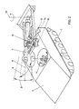
- FIG. 1 shows a conventional launcher system which is attached to a motor vehicle
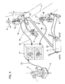
- 2 shows a device according to the invention, an armored vehicle being shown here
- FIG. 3 details of the straightening device for a device according to FIG. 2.
- FIG. 1 shows a motor vehicle 1 on which a launcher system 2 is pivotably articulated.
- the launcher system 2 can be swiveled up onto the loading platform 3 of the motor vehicle 1, the launcher system 2 being lowered into the position shown in FIG. 1 in the firing position.
- directional optics 4 are provided, which move relatively far when the tubes are pivoted in accordance with the directional kinematics of this turret system, the individual turret tubes being pivoted essentially parallel to one another and the directional kinematics having two parallelogram links 5 and on one of these parallelogram links 5 the guideline 4 is set.
- an armored weapon carrier 6 which has a crawler track 7.
- the straightening attachment 4 is pivotably arranged.
- only one weapon barrel 7 is provided and to this weapon barrel, which can be pivoted vertically in the direction of the double arrow 8 and pivoted laterally in the direction of the double arrow 9, measuring transducers are connected.
- the pivot axis for the side pivoting is indicated with 10 and the tube axis itself with 11.
- the transducers for the side and elevation angles are indicated schematically at 12 and 13, the transducer for the side pivoting being connected to the fixed system at the coupling point 15 via a flexible shaft 14.
- the details of this sensor arrangement on the weapon barrel are clearly shown in FIG.
- the transducer for the side angle corresponding to the pivoting in the sense of the double arrow 9 is again designated 13.
- the flexible shaft 14 is connected to the fixed system and the sensor 13 thus immediately results in a relative lateral pivoting relative to the stationary system.
- the determined relative lateral angle can be fed directly to a display device 17 via measuring lines 16.
- the transducer 12 is arranged in the vertical pivot axis of the tube 7, the measured value transducer 12 for the vertical angle immediately gives a vertical pivot value relative to the stationary system, and measuring lines 18 are provided for the transmission of these measured values to the display device 17.
- the transducers 12 and 13 can be connected to one another via a common carrier 19 and, for example, by serial querying of the measured values of the two transducers instead of two separate measuring lines 16 and 18, a common measuring line can be used.
- the swivel drives 20 are also provided for the lateral direction and 21 for the height direction, the corresponding control device for the hydraulic application of these swivel drives 20 and 21 being designated by 22.
- the straightening attachment 4 is connected in an analogous manner to measurement sensors, the measurement lines being designated 23 and being connected to the display or evaluation device 17.
- the fixed system for the weapon barrels and the aiming attachment are identical, such as, for example, when arranged on an armored vehicle 6, parallax errors do not occur during rough pivoting, since the directional optics are pivoted about a fixed height directional axis.
- the lateral directional angles are also determined directly in a comparable manner on the basis of their reference to the same stationary system, so that parallaxes do not occur.
Landscapes
- Engineering & Computer Science (AREA)
- General Engineering & Computer Science (AREA)
- Aiming, Guidance, Guns With A Light Source, Armor, Camouflage, And Targets (AREA)
Applications Claiming Priority (2)
| Application Number | Priority Date | Filing Date | Title |
|---|---|---|---|
| AT328987 | 1987-12-14 | ||
| AT3289/87 | 1987-12-14 |
Publications (1)
| Publication Number | Publication Date |
|---|---|
| EP0373283A1 true EP0373283A1 (fr) | 1990-06-20 |
Family
ID=3548263
Family Applications (1)
| Application Number | Title | Priority Date | Filing Date |
|---|---|---|---|
| EP88890317A Withdrawn EP0373283A1 (fr) | 1987-12-14 | 1988-12-14 | Dispositif de pointage pour système d'armes à tir plongeant mobile |
Country Status (1)
| Country | Link |
|---|---|
| EP (1) | EP0373283A1 (fr) |
Cited By (4)
| Publication number | Priority date | Publication date | Assignee | Title |
|---|---|---|---|---|
| WO1997048959A1 (fr) * | 1996-06-20 | 1997-12-24 | Dynamit Nobel Graz Ges.Mbh | Arme a tir vertical, notamment arme lance-grenades |
| WO2000025082A1 (fr) * | 1998-10-23 | 2000-05-04 | Precision Remotes, Inc. | Systeme de visee telepresent rapide |
| EP2956738B1 (fr) | 2013-02-12 | 2017-04-19 | NEXTER Systems | Systeme d'arme leger |
| EP2538166B1 (fr) * | 2011-06-22 | 2018-09-19 | Diehl Defence GmbH & Co. KG | Dispositif de conduite de tir |
Citations (3)
| Publication number | Priority date | Publication date | Assignee | Title |
|---|---|---|---|---|
| US2578666A (en) * | 1946-01-31 | 1951-12-18 | Jr Joseph L Borden | Gun control apparatus |
| US3288030A (en) * | 1963-07-01 | 1966-11-29 | Bofors Ab | Fire control system for weapons |
| EP0016490A1 (fr) * | 1979-03-23 | 1980-10-01 | Werkzeugmaschinenfabrik Oerlikon-Bührle AG | Procédé de pointage indirect d'une pièce d'artillerie et dispositif pour la mise en oeuvre du procédé |
-
1988
- 1988-12-14 EP EP88890317A patent/EP0373283A1/fr not_active Withdrawn
Patent Citations (3)
| Publication number | Priority date | Publication date | Assignee | Title |
|---|---|---|---|---|
| US2578666A (en) * | 1946-01-31 | 1951-12-18 | Jr Joseph L Borden | Gun control apparatus |
| US3288030A (en) * | 1963-07-01 | 1966-11-29 | Bofors Ab | Fire control system for weapons |
| EP0016490A1 (fr) * | 1979-03-23 | 1980-10-01 | Werkzeugmaschinenfabrik Oerlikon-Bührle AG | Procédé de pointage indirect d'une pièce d'artillerie et dispositif pour la mise en oeuvre du procédé |
Cited By (5)
| Publication number | Priority date | Publication date | Assignee | Title |
|---|---|---|---|---|
| WO1997048959A1 (fr) * | 1996-06-20 | 1997-12-24 | Dynamit Nobel Graz Ges.Mbh | Arme a tir vertical, notamment arme lance-grenades |
| AT408690B (de) * | 1996-06-20 | 2002-02-25 | Dynamit Nobel Graz Gmbh | Steilfeuergeschütz, insbesondere granatwerfer |
| WO2000025082A1 (fr) * | 1998-10-23 | 2000-05-04 | Precision Remotes, Inc. | Systeme de visee telepresent rapide |
| EP2538166B1 (fr) * | 2011-06-22 | 2018-09-19 | Diehl Defence GmbH & Co. KG | Dispositif de conduite de tir |
| EP2956738B1 (fr) | 2013-02-12 | 2017-04-19 | NEXTER Systems | Systeme d'arme leger |
Similar Documents
| Publication | Publication Date | Title |
|---|---|---|
| DE3790614C2 (fr) | ||
| DE2901873A1 (de) | Feuerleiteinrichtung | |
| DE102008056112A1 (de) | Mörser | |
| EP0359950B1 (fr) | Procédé et dispositif de visée pour l'alignement grossier de systèmes d'armes et de conduites de tir | |
| DE2143871C2 (de) | Feuerleitvorrichtung zur Richtkorrektur | |
| EP0373283A1 (fr) | Dispositif de pointage pour système d'armes à tir plongeant mobile | |
| DE19532743C2 (de) | Vorrichtung zum Richten einer Waffe eines bewaffneten Fahrzeuges | |
| EP0016490A1 (fr) | Procédé de pointage indirect d'une pièce d'artillerie et dispositif pour la mise en oeuvre du procédé | |
| EP0123012A1 (fr) | Disposition d'adjustement d'horizon pour une plate-forme rotative d'armes | |
| EP0428825A2 (fr) | Chargeur pour mortier à chargement par la bouche | |
| EP3350536B1 (fr) | Tourelle téléopérée et procédé de commande d'une tourelle téléopérée | |
| DE1274473B (de) | Feuerleitanlage fuer Schiffe | |
| DE1800330C3 (de) | Panzerfahrzeug mit Fliegerabwehrbewaffnung | |
| DE2360498C2 (de) | Einrichtsystem für Batterien schwerer auf Lafetten fahrender Waffen, insbesondere Raketenwerfer | |
| DE3212729C2 (fr) | ||
| DE69419170T2 (de) | Flugabwehrkanone mit kamera | |
| DE102013111644A1 (de) | Verfahren zur Steuerung einer richtbaren Waffe eines Fahrzeugs bei Schießübungen | |
| DE283247C (fr) | ||
| DE3409538C1 (de) | Verfahren und Vorrichtung zum Ausrichten zweier Drehebenen | |
| DE2744819C2 (de) | Verfahren und Vorrichtung zur gegenseitigen Justierung eines Sichtgerätes und einer mit diesem verbundenen, insbesondere servogesteuerten Einrichtung | |
| DE3121142C1 (en) | Anti-tank gun on tracked carriage - has barrel offset from centre and with limited traverse | |
| DE226848C (fr) | ||
| DE308448C (fr) | ||
| DE346107C (de) | Richteinrichtung mit unabhaengiger Ziellinie nach Hoehe und Seite | |
| DE3333425C2 (fr) |
Legal Events
| Date | Code | Title | Description |
|---|---|---|---|
| PUAI | Public reference made under article 153(3) epc to a published international application that has entered the european phase |
Free format text: ORIGINAL CODE: 0009012 |
|
| AK | Designated contracting states |
Kind code of ref document: A1 Designated state(s): AT BE CH DE ES FR GB GR IT LI LU NL SE |
|
| STAA | Information on the status of an ep patent application or granted ep patent |
Free format text: STATUS: THE APPLICATION IS DEEMED TO BE WITHDRAWN |
|
| 18D | Application deemed to be withdrawn |
Effective date: 19901221 |