EP0370505B1 - Roue à pivot avec dispositif de blocage - Google Patents
Roue à pivot avec dispositif de blocage Download PDFInfo
- Publication number
- EP0370505B1 EP0370505B1 EP89121662A EP89121662A EP0370505B1 EP 0370505 B1 EP0370505 B1 EP 0370505B1 EP 89121662 A EP89121662 A EP 89121662A EP 89121662 A EP89121662 A EP 89121662A EP 0370505 B1 EP0370505 B1 EP 0370505B1
- Authority
- EP
- European Patent Office
- Prior art keywords
- lever
- locking
- housing
- locking lever
- castor according
- Prior art date
- Legal status (The legal status is an assumption and is not a legal conclusion. Google has not performed a legal analysis and makes no representation as to the accuracy of the status listed.)
- Expired - Lifetime
Links
Images


Classifications
-
- B—PERFORMING OPERATIONS; TRANSPORTING
- B60—VEHICLES IN GENERAL
- B60B—VEHICLE WHEELS; CASTORS; AXLES FOR WHEELS OR CASTORS; INCREASING WHEEL ADHESION
- B60B33/00—Castors in general; Anti-clogging castors
- B60B33/02—Castors in general; Anti-clogging castors with disengageable swivel action, i.e. comprising a swivel locking mechanism
- B60B33/021—Castors in general; Anti-clogging castors with disengageable swivel action, i.e. comprising a swivel locking mechanism combined with braking of castor wheel
Definitions
- the invention relates to a roller, in particular a steering roller, consisting essentially of a fork-shaped roller housing with a fork bridge and two fork arms, an impeller mounted rotatably between the fork arms, in particular a rotating ring mounted in the fork bridge on the apparatus connection side, and a locking device mounted on the roller housing with a movably mounted locking device , spring-loaded, approximately tangential to the circumference of the impeller arranged locking lever and a movably mounted, spring-loaded, with the locking lever cooperating release lever, the locking lever is preferably movable by foot actuation from a release position into a locked position, in which it can be moved against the impeller , A locking element acting against its tread, the first lever arm the impeller and in particular with a movable against the slewing ring, with a toothing of the Interacting turntable, second lever arm also detects the turntable, and the locking lever can be moved back into the release position by actuating the release lever by releasing its locking due
- Such a running or steering roller is known from DE-C 33 44 348.
- the locking device provided in this known swivel castor has a locking lever which is pivotally mounted on the roller housing and is designed as a foot pedal lever, which carries a brake cam which can be moved against the impeller and is locked in the locking position by a release lever.
- the release lever is designed as an angle lever which is also pivotably mounted on the roller housing, one lever arm forming an actuating plate, while the second lever arm is formed by two arms which are angled at right angles on the side edges of the actuating plate and which penetrate through the openings in the roller housing or in the fork bridge and in the foot pedal lever.
- Each of these arms has a step-shaped locking edge, which is operatively connected to the foot pedal lever in such a way that a step of the locking edges rests on an edge of the respective opening of the foot pedal lever in the determination and additionally also in an intermediate position in which only the turntable is blocked , whereby the foot pedal lever is locked in each of these positions.
- the present invention is therefore based on the object to provide a roller of the type described above, the locking device for a fixed role, i.e.
- the impeller and, in the case of a swivel castor which can be pivoted about a vertical axis, the impeller and the turntable can be reliably determined regardless of the wheel diameter, diameter tolerances and regardless of the different properties of the wheel treads, even without adjustment work, while still being structurally simple and inexpensive the manufacture is.
- the locking lever can be locked in practically any position over its lever path, whereby the lock can also be released from any position by operating the release lever.
- the locking lever can advantageously be carried out with a very large lever travel, so that the locking device according to the invention works absolutely reliably in a very large range regardless of the diameter, diameter tolerances and tread formation of the wheel used in each case, advantageously even without adjustment or adjustment work.
- the locking device is mounted indirectly on the roller housing via a separate locking housing, the locking lever and the release lever being fastened to the locking housing.
- the locking device forming a separate assembly can be mounted in the simplest way on each suitable roller housing, whereby no adjustments are required here either due to the invention.
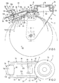
- a swivel castor 2 is shown as an example in the drawing, but the invention can also be readily implemented with fixed, so-called fixed castors.
- the steering roller 2 consists essentially of a fork-shaped roller housing 4 with a fork bridge 6 and two fork arms 8 adjoining it at right angles downwards, between which an impeller 12 is rotatably mounted on an axis 10. 1, 6, 9 and 12 each impellers 12 with different diameters are indicated.
- diameter tolerances d of up to ⁇ 3 mm can occur, which previously led to the problems already described above when determining the impeller 12.
- the swivel castor 2 For attachment on the apparatus side, the swivel castor 2 has, in a manner known per se, a turntable 16 mounted in the fork bridge 6, in particular via roller bearings 14, which enables the swivel castor 2 to pivot or steer about a vertical axis 18.
- a locking device 20 is mounted on the roller housing 4, which consists of a pivotally mounted, spring-loaded, approximately tangentially to the circumference of the impeller 12 arranged locking lever 22 and a pivotally mounted, spring-loaded, with the locking lever 22 for locking and releasing release lever 24.
- the locking lever 22 is preferably operated by foot actuation from a loose position (dashed lines in FIGS. 1 and 6 and shown in full in FIGS. 9 and 12) into a locking position locked by the release lever 24 (fully in FIGS. 1 and 6 and in FIG.
- first lever arm 28 which is movable against the impeller 12 and has a locking element 26 acting against its tread, and with a movable against the turntable 16, cooperating with a toothing 30 of the turntable 16, second lever arm 32 also detects the slewing ring 16.
- the locking device 20 can be mounted directly on the roller housing 4, the locking lever 22 and the release lever 24 preferably being attached to the underside of the fork bridge 6.
- the locking device 20 is mounted indirectly on the roller housing 4 via a separate locking housing 34, the locking lever 22 and the release lever 24 being fastened to the locking housing 34.
- the arrester housing 34 is formed according to the invention essentially in a U-shape from a web wall 36 and two leg walls 38 perpendicular thereto, the arrester housing 34 overlapping the roller housing 4 in regions.
- the web wall 36 rests in regions on the fork bridge 6, and the leg walls 38 lie in regions on the outside of the fork arms 8.
- 1 to 8 according to the invention has a cut out of the web wall 36 or a U-shaped cutout 39 (FIG.
- the fork arms 8 and the leg walls 38 each have through holes that are aligned with one another in all versions, through which a fastening bolt 42, for example a bolt, extends and is screwed to a nut 44.
- a fastening bolt 42 for example a bolt
- a rivet bolt or the like could also be used.
- the locking device 20 can be arranged in the direction of the steering roller 2 or the wheel 12 alternatively in the area in front or behind the axis 10.
- the release lever 24 runs approximately parallel to the first lever arm 28 of the locking lever 22 between the latter and the housing or web wall 36.
- the web wall 36 has two sections, seen in the circumferential direction of the impeller 12, which merge into one another at an obtuse angle , whereby it is adapted approximately to the circumferential contour of the impeller 12 (see FIGS. 1, 6, 9 and 12). 6, 9 and 12, the locking lever 22 is also adapted to this course by a correspondingly angular design between the first lever arm 28 and the second lever arm 32.
- first lever arm 28 of the locking lever 22 extends approximately perpendicular to the locking lever 22 and to the release lever 24 away from the impeller 12 and through a housing opening 46 of the housing or web wall 36 connected locking element 48, which in the illustrated embodiments of the invention consists of a substantially L-shaped sheet metal strip, with a longer L-leg 50 preferably self-locking in an opening 52 of the locking lever 22 or its first lever arm 28 pressed (Fig. 1 to 8) or riveted to the locking lever 22 (Fig. 9 to 11), extends through a through opening 54 of the release lever 24 and the housing opening 46 and above the housing or web wall 36 in a shorter , an L-leg 58 having an upper-side tread surface 56 merges.
- the release lever 24 is pivotally mounted such that when it is actuated in the direction of arrow 64 according to FIGS. 1, 6, 9 and 12, the contact edge 62 removes the non-positive and / or positive engagement away from the leg 50 of the locking element 48.
- the locking element 48 is released together with the locking lever 22, so that the latter can move back from the detection by spring force back into the broken position shown in broken lines.
- the contact edge 62 of the release lever 24 is preferably formed by an opening edge of the through opening 54 of the release lever 24 which is penetrated by the longer leg 50 of the locking element 48.
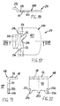
- FIGS. 4 and 5 The leaf springs used as locking lever 22 and release lever 24 in the first embodiment according to FIGS. 1 to 3 are shown in detail in FIGS. 4 and 5.
- the locking lever 22 consists of a one-piece stamped part 65 made of spring sheet metal with an essentially rectangular, broader surface section 66 forming the first lever arm 28, which merges via oblique edges 68 into a narrower surface section 70 forming the second lever arm 32.
- a crank 72 (recognizable in FIG. 1) is formed such that in the assembled state the first lever arm 28 is closer to the impeller 12 than the second lever arm 32.
- the narrower surface section 70 has a central one , U-shaped cut-out 74, the U-legs 76 of this cut-out 74 extending from the U-web 78 lying in the region of the offset 72 in the direction of the free end of the second lever arm 32 approximately to the middle of its length.
- a cut-out tongue 80 which has an approximately central fastening hole 82, is saved through the cutout 74.
- This fastening tongue 80 is fastened, for example, to the underside of the holding tongue 40 of the locking housing 34 via a rivet connection 84 which extends through the fastening hole 82 (see FIG. 1).
- the U-shaped cutout 72 furthermore forms webs 86 on both sides of the fastening tongue 80.
- the fastening tongue 80 forms a predetermined bending point 88 in its region lying between the fastening hole 82 and its connected end and thus a pivot point for the locking lever 22.
- the second lever arm 32 or the narrower surface section 70 of the stamped part 65 has an arcuate end edge 92 adapted to the circumferential contour of the toothing 30 of the rotating ring 16, preferably with three spaced apart in the circumferential direction of the rotating ring 16, in the determination in the one on the outer circumference Ball sleeve 93 of the rotating ring 16 formed toothing 30 engaging locking cams 94.
- the wider surface section 66 of the stamped part 65 has in its area facing the narrower surface section 70 an approximately H-shaped cutout 96 with two parallel sections 98 running in the longitudinal direction of the locking lever 22 and a transverse section 100 connecting these in the central area.
- two locking tongues 102 which form the locking element 26 and are located opposite one another in the circumferential direction of the impeller 12 and bent obliquely downward in the direction of the tread of the impeller 12 (see also FIG. 1).
- the wider surface section 66 of the stamped part 65 has the opening 52 in its free end region, which is formed here as a rectangular cutout 104 which extends transversely to the longitudinal direction of the lever and which has two parallel cutouts which extend in the direction of the narrower surface section 70 106 merges, these two cutouts 106 forming a clamping tongue 108 between them. It is essential that this clamping tongue 108 has a length such that it protrudes somewhat into the opening of the rectangular cutout 104. In terms of shape, the rectangular cutout 104 corresponds approximately to the cross section of the longer L-leg 50 of the locking element 48. By this configuration, pushing the end of the L-leg 50 into the rectangular cutout 104 results in a self-clamping holder via the slightly resiliently bending clamping tongue 108 (see see also Fig. 6).
- the release lever 24 also consists of a one-piece spring plate stamped part 110, which in this example has a substantially rectangular shape.
- the stamped part 110 has two fastening holes 112 in an arrangement symmetrical with respect to the longitudinal center axis.
- a rectangular cutout 114 is arranged at a distance from the fastening holes 112 in the direction of the other end, as a result of which two lateral edge webs 116 are formed which define a predetermined bending point 118 and thus a pivot point for the release lever 24.
- the spring elasticity or the spring force can be influenced via different widths of the webs 116.
- the stamped part 110 also has a rectangular shape Cutout formed through opening 54, with on a transverse web 120 separating the cutout 114 from the through opening 54 a barb protruding into the through opening 54, bent obliquely approximately in the direction of the fastening area between the locking lever 22 and the end of the longer leg 50 of the locking element 48 is connected (see also Fig. 1).
- the abovementioned contact edge 62 is formed, the function of which will be explained in the following.
- the end of the stamped part 110 which is remote from the fastening holes 112 forms a flat actuating section 123 which is slightly rounded at the end.
- the release lever 24 shown in FIG. 5 is fastened according to FIGS. 1 to 3 via two rivet connections 125 passing through the fastening holes 112 on the underside of the web wall 36 of the locking housing 34.
- this attachment _ as already mentioned above _ the locking lever 22 shown in FIG. 4 according to FIGS. 1 and 3 is separately attached to the underside of the retaining tongue 40 of the frame housing 34 via the individual rivet connection 84 with the attachment tongue 80.
- any other connecting means or connection types are of course also possible without departing from the scope of the invention. For example, screw connections and integral connections (adhesive) are mentioned here.
- FIGS. 7 and 8 The leaf springs used in the second embodiment according to FIG. 6 as locking lever 22 and release lever 24 are shown in FIGS. 7 and 8. These leaf springs only differ from those of FIGS. 4 and 5 insignificant, so that the differences will only be briefly discussed below.
- the same parts are provided with the same reference numerals of the other figures, so that reference can also be made to the above statements in this regard.
- the release lever 24 here consists of a one-piece spring plate stamped part 124 with a narrower section 126, which merges via oblique edges 128 into a wider section 130 forming the free end of the release lever 24.
- a centrally arranged fastening hole 112 is formed in the end region of the narrower section 126. Otherwise, reference is made to the explanations relating to FIG. 5.
- the release lever 24 (FIG. 7) and the locking lever 22 (FIG. 8) are advantageously fastened on the housing side via a common rivet connection 134 penetrating through the fastening holes 82 and 112, for which purpose in this case in an adjacent or a corresponding fastening hole (not designated) is arranged behind the retaining tongue 40 of the area of the web wall 36 of the locking housing 34.
- a common rivet connection 134 penetrating through the fastening holes 82 and 112
- any other type of connection can of course also be selected here (screws, integral connection, etc.).
- the locking lever 22 and the release lever 24 are formed together by a single, one-piece leaf spring.
- This leaf spring consists of a one-piece spring sheet metal stamping part 140, shown as "development” in FIG. 11, which has a narrower end section 142 at one end and a wider end section 144 at the other end, these two sections 142, 144 merging into one another via inclined edges 146.
- the narrower end section 142 forms the second lever arm 32 of the locking lever 22 and therefore has the circular-arc-shaped end edge 92 already described above with the locking cams 94 connected to it, although in this example only two locking cams 94 are provided.
- the punched part 140 has an approximately U-shaped cutout 148 in its central region with two mutually parallel, symmetrical to the longitudinal axis of the lever From the actuating section 123 to beyond the region of the oblique edges 146, a portion of leg cutouts 150 extending into the region of the narrower end section 142, which merge into one another on the side of the actuating section 123 via a connecting cutout 142 arranged perpendicular to the longitudinal axis of the lever.
- a spring tongue 154 forming the first lever arm 28 of the locking lever 22 is thus cut free by the U-shaped cutout 148 and has in its free end region a web 158 bent over a bending line 156 in the direction of the impeller 12, which in this exemplary embodiment has the locking element 26 Locking lever 22 forms (see also Fig. 9 and 10). Furthermore, the spring tongue 154 has in itself the end region adjoining the web 158, the opening 52 designed in the example shown as a square fastening opening 160 for fastening (riveting) the longer L-leg 50 of the locking element 48.
- the U-shaped cutout 148 also forms two lateral edge webs 162, via which the locking lever 22 is connected in one piece to the release lever 24. Approximately in its central region, each of the edge webs 162 has a fastening hole 164, the fastening holes 164 defining the boundary between the release lever 24 and the locking lever 22.
- the release lever 24 is also essentially U-shaped from sections of the edge webs 162 and the actuating section 123 connecting them.
- the leg cutouts 150 of the U-shaped cutout 148 widen in the region of the release lever 24 shortly before the transition to the connection cutout 152 via step edges 166 that protrude outwards.
- the edge webs 162 are dashed through in FIG. 11
- the incisions 168 which extend in the longitudinal direction of the lever, cut out two locking tongues 170, which are bent around bending lines 172 which are also shown in dashed lines (analogously to the locking tongue 122 of the exemplary embodiments according to FIGS. 1 to 8).
- the step edges 166 arranged after the bending at the free ends of the locking tongues 170 form the contact edge 62, which here is divided into two (see the exemplary embodiments according to FIGS. 1 to 8).
- the wider end section 144 of the stamped part 140 has on both sides an edge web attachment 174 with a bending line 176 bent approximately at right angles around a bending line 176 shown in dashed lines in FIG. 11 (see also FIG. 10).
- stiffening webs 178 Because of these stiffening webs 178, a predetermined bending point 180 and thus a pivot point for the release lever 24 is formed in the region of the edge webs 162 lying between these and the fastening holes 164, whereby in each case it is ensured on the basis of the stiffening webs 178 that when the release lever 24 is pivoted about one Pressure on the actuating section 123, the locking tongues 170 are also "taken along", which is important for the function of the locking device according to the invention, as will be explained below.
- edge webs 162 facing away from the release lever 24 are subdivided via the inclined edges 146 into a wider section 182 facing the fastening hole 164 and a narrower section 184 facing away from the fastening hole 164, a predetermined bending point 186 and in each of the narrower sections 184 so that a pivot point for the locking lever 22 is formed, about which this _ as well as in the embodiments already described _ can move like a rocker.
- the sections 182 and 184 of the edge webs 162 merge into one another via such cranks 188 that the first lever arm 28 of the locking lever 22 is arranged in a plane “below” the release lever 24 (see FIG. 11).
- a section 189 of the edge webs 162 lying between two crankings 188 runs parallel to the web wall 36 of the locking housing 34 at a distance from the Web wall 36, which corresponds approximately to the thickness of the material of the fork bridge 6.
- these sections 189 of the edge webs 162 engage under the fork bridge 6 approximately analogously to the holding tongue 40 of the exemplary embodiments according to FIGS. 1 to 8.
- This holding tongue 40 can therefore advantageously be used in this exemplary embodiment according to FIGS. 9 to 11 spare.
- the edge webs 162 resting on the underside of the web wall 36 of the frame housing 34 are riveted to the web wall 36 in the region of the fastening holes 164 (see the rivet connection 190 in FIG. 9), or else to other suitable ones Art attached (gluing, screwing).
- the release lever 24 advantageously consists of a _ in contrast to the previously described leaf spring stamping parts _ dimensionally stable sheet metal part 210 (see also FIGS. 17 and 18), which is "floating" between the web wall 36 and the locking lever 22.
- the sheet metal part 210 consists of the substantially approximately rectangular actuating section 123 and a bearing tongue 212 which is bent upwards in the direction of the web wall 36 and which _ is forming a tilting or pivoting bearing _ is supported on the underside of the web wall 36 (see FIG. 12). It also extends here the locking element 48 (shown in FIGS. 19 and 20) with the longer L-leg 50 through the through opening 54 of the release lever 24, wherein according to FIG.
- the sheet metal part 210 projects inward into the through opening 54 with clamping projections 214 in this case each has a contact edge 62, which reinforce the described frictional engagement between the release lever 24 and the locking element 48, by the locking element 8 is held clamped between the opposite contact edges 62 when the release lever 24 is pivoted or tilted.
- the sheet metal part 210 forming the release lever 24 is thus held here exclusively by the locking element 48 extending through the through opening 54.
- the locking lever 22 is preferably formed in two parts from two leaf spring stamping parts, namely a first stamping part 216 having the second lever arm 32 with the locking cams 94 (see also FIGS. 13 and 15) and a first lever arm 28 with the Locking element 26 or the second punched part 218 forming the locking tongues 102 (see also FIGS. 14 and 16).
- the first stamped part 216 corresponds essentially to the stamped part 140 of the embodiment according to FIGS. 9 to 11, so that reference can be made here to the above explanations.
- the spring tongue 154 is used exclusively for the resilient support of the locking element 48 and thus for the pivoting of the second lever arm 32 about the predetermined bending points 186, so that the web 158 forming the locking element 26 of the spring tongue 154 can be omitted here.
- the edge webs 162 merge in one piece into two lateral spring tongues 222, on which the release lever 24 or the sheet metal part 210 is supported in a resilient manner.
- the spring tongues are for this 222 at the end in each case in the area next to the passage opening 54 under elastic prestress on the actuating section 123 of the sheet metal part 210.
- the spring tongue 154 here also has the fastening opening 160 for the locking element 48, but here no riveting is provided between the locking element 48 and the spring tongue 154, but the locking element 48 extends with a central bearing pin 223 of the longer L- which is preferably square in cross section.
- Leg 50 (see FIG. 20) with a small circumferential play into the fastening opening 160, which allows slight movements between the spring tongue 154 and the locking element 48, which advantageously has a favorable effect on the clamping action between the release lever 24 and the locking element 48.
- the second stamped part 218 is detachably mounted on the first stamped part 216, on its side facing the impeller 12.
- the second stamped part 218 has, on a narrow side of a rectangular main part 224, a retaining tongue 226 (FIGS. 14 and 16) which is bent at an obtuse angle upwards in the direction of the first stamped part 216 and which extends into a slot opening formed in the region adjoining the end edge 92 228 of the first stamped part 216 (see FIG. 15) engages in a non-positive and / or positive manner, as can be clearly seen in FIG. 12.
- the second punched part 218 has two lateral, mutually parallel, approximately integrally formed in the central region of the main part 224 on the longitudinal edges of the retaining tabs 226 pointing away from the retaining tongue 226, which in the assembled state in lateral recesses 232 (see FIG. 20) in the end region of the longer leg 50 of the locking element 48 engage.
- the locking element 48 and the second stamped part 218 are advantageously held practically mutually, because "slipping out" of the locking element 48 upwards is prevented according to the invention by the holding webs 230 engaging in the recesses 232.
- the area of the main part 224 of the second stamping part 218 opposite the holding tongue 226 forms the first lever arm 28 of the locking lever 22 and therefore has the locking element 26, which in turn is formed by free and bent locking tongues 102. Since the second stamped part 218 bears in this area on the spring tongue 154 of the first stamped part 216 (can be seen in FIG. 12), the locking element 26 for locking the impeller 12 can be moved in an approximately radial direction by means of the locking element 48.
- the locking element 48 has two lateral inclined surfaces 234 at the free end of the longer leg 50, the function of which will be explained in the following.
- the locking device 20 is now assembled as follows.
- the first stamped part 216 is fastened to the underside of the web wall 36 via the rivet connections 190.
- the release lever 24 or the sheet metal part 210 is guided with the bearing tongue 212 ahead between the web wall 36 and the spring tongue 154 of the first stamped part 216 until the through opening 54 is approximately aligned with the opening 46 of the web wall 36, so that the locking element 48 then its longer leg 50 can be inserted through the two openings.
- the bearing pin 223 engages in the fastening opening 160 of the spring tongue 154.
- the second stamped part 218 is assembled by first holding it with the holding tongue 226 in the Slot opening 228 of the first stamped part 216 is inserted.
- the opposite end of the stamped part 218 is moved in the direction of the first stamped part 216 until the lateral holding webs 230 hit the inclined surfaces 234 of the longer leg 50 of the locking element 48 and are thereby pushed outward in a spring-elastic manner until they snap into the lateral recesses 232. Disassembly is advantageously also possible in the reverse order.
- the locking tongue 122 of the release lever 24 acts with its contact edge 62 in the exemplary embodiment according to FIG. rubbing together with the surface of the longer leg 50 of the locking element 48. 1 to 5, the locking element 48 according to the invention has a serration 192 on the surface of the longer L-leg 50 facing the contact edge 62 of the release lever 24, into which the contact edge 62 of the locking tongue 122 of the release lever 24 has a positive or non-positive fit intervenes.
- the step edges 166 of the locking tongues 170 forming the contact edge 62 and on the other hand in the embodiment according to FIGS. 12 to 20 the contact edges 62 of the clamping projections 214 of the sheet metal part 210 forming the release lever 24 each have a positive connection, ie rubbing together with the locking element 48.
- This pretensioning or contact force of the release lever 24 via the contact edge 62 is advantageously increased the further the first lever arm 28 is “tensioned”, that is to say it is locked, because when the lever arm 28 is pivoted, the locking element 48 connected to it moves in the direction of the contact edge 62, because the free end of the lever arm 28 moves in a circular path around its pivot point (predetermined bending point 88 or 186).
- the locking lever 22 can be locked via the locking element 48 advantageously in almost any position over its lever path, so that a lock can always be achieved even with different impellers 12, in which the impeller 12 is securely fixed.
- the second lever arm 32 of the locking lever 22 in its locking which locks the rotating ring 16 preferably bears against a stop 194 on the housing side (see FIGS. 1, 6, 9 and 12).
- This stop 194 can through the underside (s) surface (s) of the fork bridge 6 of the roller housing 4 (Fig. 1, 9 and 12) and / or the retaining tongue 40 of the lock housing 34 (Fig. 6) may be formed.
- This embodiment is advantageous insofar as _ as soon as the slewing ring 16 is locked from a certain position of the locking lever 22 or the locking element 48 _ the first lever arm 28 of the locking lever 22 can subsequently be "re-tensioned” for secure locking of the impeller 12, without influencing the detection of the slewing ring 16, since with such a "re-tensioning” the second lever arm remains in abutment against the stop 194 due to the spring elasticity and thus in the position that detects the slewing ring 16.
- the locking tongues 102 forming the locking element 26 (FIGS. 1 to 8 and 12 to 20) and the web 158 (FIGS. 9 to 11) come to rest on the running surface of the impeller 12 with their free end edges. As a result, a reliable determination is always guaranteed, regardless of any profiling of the impeller 12.
- the release lever 24 preferably extends forwards with the actuating section 123 over the locking lever 22 and also over the shorter L-leg 58 of the locking element 48, with a cap-like cover 196 on the actuating section 123, which is only shown in FIGS. 5, 6 and 7 each indicated by dashed lines and shown in section in Fig. 9 is attached.
- This coating 196 can be formed, for example, by a plastic coating.
- Lateral recesses 198 in the actuating section 123 as shown by way of example in FIGS. 10 and 11, and, if appropriate, by recesses in the surface area of the actuating section 123 (not shown), allow a positive fit and thus a good fit Holder of the coating 196 can be achieved.
- the release lever 24 due to the design as a dimensionally stable sheet metal part, has an increased stability in comparison to the leaf springs, so that a release from the determination advantageously also easily takes place against very high clamping forces is.
- the locking device 20 is equipped with an acoustic signal device, in particular, which, at a certain minimum locking force, emits an acoustic signal, e.g. a crackling sound.
- an acoustic signal device in particular, which, at a certain minimum locking force, emits an acoustic signal, e.g. a crackling sound.
- the locking lever 22 is pivoted by foot actuation of the locking element 48, ie by pressure in the direction of arrow 200 on the tread surface 56 of the L-leg 58, into the locking position in which the first lever arm 28 with the locking element 26, ie the locking tongues 102 or the web 158, rests on the running surface of the impeller 12 and the second lever arm 32 engages with the locking cams 94 in the toothing 30 of the turntable 16.
- the release lever 24 needs to be pivoted in the direction of arrow 64, which can advantageously also be done by foot operation, this pivoting movement causing the contact edge 62 of the release lever 24 from the locking element 48 moves away, so that the frictional engagement between the locking element 48 and the opening edge 60 is canceled.
- the locking lever 22 can thereby move back into the release position due to its spring elasticity, the L-leg 50 of the locking element 48 being able to move freely through the through opening 54 of the release lever 24 and through the housing opening 46 in the direction of the arrow 202.
- the running or steering roller 2 of the invention is advantageously structurally extremely simple and, as a result, is also inexpensive to manufacture and assemble.
- the locking lever 22 and the release lever 24 are a one-piece or as a jointly one-piece leaf spring (s), no bearing points are required, but the pivoting mobility of these levers is achieved solely by their spring elasticity in the predetermined bending points.
- the locking device 20 can also be mounted directly on the roller housing 4, the locking lever 22 and the release lever 24 in this case would be attached to the roller housing 4 and the housing opening 46 would be formed in the fork bridge 6.
- the locking element 26 can also have any other, for example spherical shape, or can also be designed as a separate “locking shoe”, if appropriate.
- the invention defined in the patent claims can also be used without further ado in the case of rollers in which the locking device is designed exclusively as a directional lock for locking the turntable.
- the locking element 26 locking tongues 102, web 1548 of the first lever arm 28 of the locking lever 22 is omitted, and optionally a different toothing 30 is provided on the rotating ring 16 in connection with a modified design of the locking cams 94 of the second lever arm 32 of the locking lever 22. It is then possible to fix the direction of the swivel castor 2 without locking the wheel (straight running).
Landscapes
- Engineering & Computer Science (AREA)
- Mechanical Engineering (AREA)
- Lock And Its Accessories (AREA)
- Clamps And Clips (AREA)
- Handcart (AREA)
- Spinning Or Twisting Of Yarns (AREA)
Claims (21)
Priority Applications (1)
| Application Number | Priority Date | Filing Date | Title |
|---|---|---|---|
| AT89121662T ATE62872T1 (de) | 1988-11-25 | 1989-11-23 | Laufrolle mit feststelleinrichtung. |
Applications Claiming Priority (2)
| Application Number | Priority Date | Filing Date | Title |
|---|---|---|---|
| DE3839842A DE3839842A1 (de) | 1988-11-25 | 1988-11-25 | Laufrolle mit feststelleinrichtung |
| DE3839842 | 1988-11-25 |
Publications (2)
| Publication Number | Publication Date |
|---|---|
| EP0370505A1 EP0370505A1 (fr) | 1990-05-30 |
| EP0370505B1 true EP0370505B1 (fr) | 1991-04-24 |
Family
ID=6367893
Family Applications (1)
| Application Number | Title | Priority Date | Filing Date |
|---|---|---|---|
| EP89121662A Expired - Lifetime EP0370505B1 (fr) | 1988-11-25 | 1989-11-23 | Roue à pivot avec dispositif de blocage |
Country Status (3)
| Country | Link |
|---|---|
| EP (1) | EP0370505B1 (fr) |
| AT (1) | ATE62872T1 (fr) |
| DE (2) | DE3839842A1 (fr) |
Families Citing this family (5)
| Publication number | Priority date | Publication date | Assignee | Title |
|---|---|---|---|---|
| US5383536A (en) * | 1991-10-29 | 1995-01-24 | Saf-T-Loc, Inc. | Foot actuated wheel brake |
| US5328000A (en) * | 1991-10-29 | 1994-07-12 | Saf-T-Loc, Inc. | Foot actuated wheel brake |
| FR2688741B1 (fr) * | 1992-03-23 | 1998-06-12 | Guittel Etienne Mobilor | Roulette pivotante pour chariot. |
| NL1023573C2 (nl) * | 2003-05-30 | 2004-12-01 | Colson Transportwielen B V | Zwenkwiel. |
| DE102016110300B4 (de) * | 2016-06-03 | 2019-04-18 | Fechtel Transportgeräte GmbH | Lenkrollenbaueinheit |
Family Cites Families (2)
| Publication number | Priority date | Publication date | Assignee | Title |
|---|---|---|---|---|
| US4110866A (en) * | 1977-11-30 | 1978-09-05 | Sugatsune Industrial Co., Ltd. | Caster equipped with a stopper |
| DE3618448A1 (de) * | 1986-04-08 | 1987-10-22 | Loh Kg Rittal Werk | Abbremsbare lenkrolle fuer eine lastaufnehmende fahrbare tragplatte |
-
1988
- 1988-11-25 DE DE3839842A patent/DE3839842A1/de not_active Withdrawn
-
1989
- 1989-11-23 DE DE8989121662T patent/DE58900096D1/de not_active Expired - Fee Related
- 1989-11-23 EP EP89121662A patent/EP0370505B1/fr not_active Expired - Lifetime
- 1989-11-23 AT AT89121662T patent/ATE62872T1/de not_active IP Right Cessation
Also Published As
| Publication number | Publication date |
|---|---|
| EP0370505A1 (fr) | 1990-05-30 |
| DE3839842A1 (de) | 1990-05-31 |
| DE58900096D1 (de) | 1991-05-29 |
| ATE62872T1 (de) | 1991-05-15 |
Similar Documents
| Publication | Publication Date | Title |
|---|---|---|
| WO2005083275A1 (fr) | Fixation par clipsage ou encliquetage permettant de fixer une paroi mince sur un support de paroi | |
| DE3910154C2 (de) | Blattfederanordnung zum Niederhalten der Bremsbelagträger in einer Scheibenbremse | |
| WO1991015685A1 (fr) | Fixation du cable de freins d'arret, notamment freins manuels en duo assistes en pot | |
| EP0370505B1 (fr) | Roue à pivot avec dispositif de blocage | |
| DE3829109C2 (de) | Elektrischer Schalter, insbesondere Lenkstockschalter für Kraftfahrzeuge | |
| EP4098526A1 (fr) | Fermeture de cadre | |
| DE4437620B4 (de) | Temperaturregler | |
| EP2026976A1 (fr) | Insert pour tampon | |
| EP2297760B1 (fr) | Interrupteur à bascule | |
| EP0754827A2 (fr) | Dispositif pour la fixation amovible et axialement non coulissante d'une poignée sur un élément de palier, notamment pour une poignée de porte ou fenêtre | |
| DE19836454C2 (de) | Bremsbare Lenkrolle für Apparate, Geräte, Möbel oder dergleichen | |
| DE3222859A1 (de) | Bremsbackenanordnung | |
| EP0730077B1 (fr) | Elément de rétention de couvercle pour boítiers de ferme-portes | |
| DE102006059096B4 (de) | Baugruppe zur fahrzeugseitigen Befestigung eines Gurtschlosses | |
| DE19652027C2 (de) | Montageschiene zur Befestigung von Rohren o. dgl. Gegenständen | |
| CH671648A5 (en) | Electric contact device for keyboard switch - uses double armed contact element between pushbutton operating element and fixed counter contact pin | |
| DE10032668B4 (de) | Reibscheiben-Kupplung mit einer Nachstelleinrichtung zum Ausgleich von Reibflächen-Verschleiß | |
| DE19546224B4 (de) | Lenkrolle mit Feststellvorrichtung | |
| DE2726608C2 (de) | Druckabhängige elektrische Schaltvorrichtung | |
| DE3031345C2 (fr) | ||
| EP0862522A1 (fr) | Dispositif de crantage de securite pour systeme de commande, notamment de freins, en cas de collision | |
| DE1413846A1 (de) | Anordnung bei Programmsteuergeraeten fuer Waschmaschinen zum UEberfahren von Programmabschnitten im Schnellgang | |
| DE3109237A1 (de) | Vorrichtung zum voruebergehenden festklemmen von material | |
| EP1534541B1 (fr) | Roue a pivot | |
| DE1640851B1 (de) | Elektrischer druckknopftaster mit einer fuehrungshuelse |
Legal Events
| Date | Code | Title | Description |
|---|---|---|---|
| PUAI | Public reference made under article 153(3) epc to a published international application that has entered the european phase |
Free format text: ORIGINAL CODE: 0009012 |
|
| AK | Designated contracting states |
Kind code of ref document: A1 Designated state(s): AT BE CH DE ES FR GB GR IT LI LU NL SE |
|
| 17P | Request for examination filed |
Effective date: 19900518 |
|
| 17Q | First examination report despatched |
Effective date: 19900810 |
|
| EL | Fr: translation of claims filed | ||
| ITCL | It: translation for ep claims filed |
Representative=s name: ORGANIZZAZIONE D'AGOSTINI |
|
| GRAA | (expected) grant |
Free format text: ORIGINAL CODE: 0009210 |
|
| AK | Designated contracting states |
Kind code of ref document: B1 Designated state(s): AT BE CH DE ES FR GB GR IT LI LU NL SE |
|
| PG25 | Lapsed in a contracting state [announced via postgrant information from national office to epo] |
Ref country code: SE Effective date: 19910424 Ref country code: NL Effective date: 19910424 Ref country code: GR Free format text: LAPSE BECAUSE OF FAILURE TO SUBMIT A TRANSLATION OF THE DESCRIPTION OR TO PAY THE FEE WITHIN THE PRESCRIBED TIME-LIMIT Effective date: 19910424 Ref country code: GB Effective date: 19910424 Ref country code: ES Free format text: THE PATENT HAS BEEN ANNULLED BY A DECISION OF A NATIONAL AUTHORITY Effective date: 19910424 Ref country code: BE Effective date: 19910424 |
|
| REF | Corresponds to: |
Ref document number: 62872 Country of ref document: AT Date of ref document: 19910515 Kind code of ref document: T |
|
| REF | Corresponds to: |
Ref document number: 58900096 Country of ref document: DE Date of ref document: 19910529 |
|
| ET | Fr: translation filed | ||
| ITF | It: translation for a ep patent filed |
Owner name: ORGANIZZAZIONE D'AGOSTINI |
|
| NLV1 | Nl: lapsed or annulled due to failure to fulfill the requirements of art. 29p and 29m of the patents act | ||
| GBV | Gb: ep patent (uk) treated as always having been void in accordance with gb section 77(7)/1977 [no translation filed] | ||
| PG25 | Lapsed in a contracting state [announced via postgrant information from national office to epo] |
Ref country code: AT Effective date: 19911123 |
|
| PG25 | Lapsed in a contracting state [announced via postgrant information from national office to epo] |
Ref country code: LU Free format text: LAPSE BECAUSE OF NON-PAYMENT OF DUE FEES Effective date: 19911130 Ref country code: LI Effective date: 19911130 Ref country code: CH Effective date: 19911130 |
|
| PLBE | No opposition filed within time limit |
Free format text: ORIGINAL CODE: 0009261 |
|
| STAA | Information on the status of an ep patent application or granted ep patent |
Free format text: STATUS: NO OPPOSITION FILED WITHIN TIME LIMIT |
|
| 26N | No opposition filed | ||
| REG | Reference to a national code |
Ref country code: CH Ref legal event code: PL |
|
| PGFP | Annual fee paid to national office [announced via postgrant information from national office to epo] |
Ref country code: DE Payment date: 19921106 Year of fee payment: 4 |
|
| PGFP | Annual fee paid to national office [announced via postgrant information from national office to epo] |
Ref country code: FR Payment date: 19921116 Year of fee payment: 4 |
|
| ITPR | It: changes in ownership of a european patent |
Owner name: CESSIONE;HEINRICH BLICKLE GMBH & CO. KG |
|
| REG | Reference to a national code |
Ref country code: FR Ref legal event code: TP |
|
| PG25 | Lapsed in a contracting state [announced via postgrant information from national office to epo] |
Ref country code: FR Effective date: 19940729 |
|
| PG25 | Lapsed in a contracting state [announced via postgrant information from national office to epo] |
Ref country code: DE Effective date: 19940802 |
|
| REG | Reference to a national code |
Ref country code: FR Ref legal event code: ST |
|
| PG25 | Lapsed in a contracting state [announced via postgrant information from national office to epo] |
Ref country code: IT Free format text: LAPSE BECAUSE OF NON-PAYMENT OF DUE FEES;WARNING: LAPSES OF ITALIAN PATENTS WITH EFFECTIVE DATE BEFORE 2007 MAY HAVE OCCURRED AT ANY TIME BEFORE 2007. THE CORRECT EFFECTIVE DATE MAY BE DIFFERENT FROM THE ONE RECORDED. Effective date: 20051123 |