EP0370505B1 - Castor with a locking device - Google Patents
Castor with a locking device Download PDFInfo
- Publication number
- EP0370505B1 EP0370505B1 EP89121662A EP89121662A EP0370505B1 EP 0370505 B1 EP0370505 B1 EP 0370505B1 EP 89121662 A EP89121662 A EP 89121662A EP 89121662 A EP89121662 A EP 89121662A EP 0370505 B1 EP0370505 B1 EP 0370505B1
- Authority
- EP
- European Patent Office
- Prior art keywords
- lever
- locking
- housing
- locking lever
- castor according
- Prior art date
- Legal status (The legal status is an assumption and is not a legal conclusion. Google has not performed a legal analysis and makes no representation as to the accuracy of the status listed.)
- Expired - Lifetime
Links
Images


Classifications
-
- B—PERFORMING OPERATIONS; TRANSPORTING
- B60—VEHICLES IN GENERAL
- B60B—VEHICLE WHEELS; CASTORS; AXLES FOR WHEELS OR CASTORS; INCREASING WHEEL ADHESION
- B60B33/00—Castors in general; Anti-clogging castors
- B60B33/02—Castors in general; Anti-clogging castors with disengageable swivel action, i.e. comprising a swivel locking mechanism
- B60B33/021—Castors in general; Anti-clogging castors with disengageable swivel action, i.e. comprising a swivel locking mechanism combined with braking of castor wheel
Abstract
Description
Die Erfindung betrifft eine Laufrolle, insbesondere Lenkrolle, im wesentlichen bestehend aus einem gabelförmigen Rollengehäuse mit einer Gabelbrücke und zwei Gabelarmen, einem zwischen den Gabelarmen drehbeweglich gelagerten Laufrad, insbesondere einem in der Gabelbrücke apparateanschlußseitig gelagerten Drehkranz sowie einer an dem Rollengehäuse gelagerten Feststelleinrichtung mit einem beweglich gelagerten, federbelasteten, etwa tangential zum Umfang des Laufrades angeordneten Feststellhebel und einem beweglich gelagerten, federbelasteten, mit dem Feststellhebel arretierend zusammenwirkenden Lösehebel, wobei der Feststellhebel vorzugsweise durch Fußbetätigung aus einer Losstellung in eine arretierte Feststellung bewegbar ist, in der er mit einem gegen das Laufrad bewegbaren, ein gegen dessen Lauffläche wirkendes Feststellelement aufweisenden, ersten Hebelarm das Laufrad sowie insbesondere mit einem gegen den Drehkranz bewegbaren, mit einer Verzahnung des Drehkranzes zusammenwirkenden, zweiten Hebelarm auch den Drehkranz feststellt, und wobei der Feststellhebel bei Betätigung des Lösehebels durch Aufhebung seiner Arretietierung aufgrund seiner Federbelastung wieder zurück in die Losstellung bewegbar ist.The invention relates to a roller, in particular a steering roller, consisting essentially of a fork-shaped roller housing with a fork bridge and two fork arms, an impeller mounted rotatably between the fork arms, in particular a rotating ring mounted in the fork bridge on the apparatus connection side, and a locking device mounted on the roller housing with a movably mounted locking device , spring-loaded, approximately tangential to the circumference of the impeller arranged locking lever and a movably mounted, spring-loaded, with the locking lever cooperating release lever, the locking lever is preferably movable by foot actuation from a release position into a locked position, in which it can be moved against the impeller , A locking element acting against its tread, the first lever arm the impeller and in particular with a movable against the slewing ring, with a toothing of the Interacting turntable, second lever arm also detects the turntable, and the locking lever can be moved back into the release position by actuating the release lever by releasing its locking due to its spring loading.
Eine derartige Lauf- bzw. Lenkrolle ist aus der DE-C 33 44 348 bekannt. Die bei dieser bekannten Lenkrolle vorgesehene Feststelleinrichtung besitzt einen am Rollengehäuse schwenkbeweglich gelagerten, als Fußpedalhebel ausgebildeten Feststellhebel, der einen gegen das Laufrad bewegbaren Bremsnocken trägt und in der Feststellung durch einen Lösehebel blockiert wird. Der Lösehebel ist als ebenfalls am Rollengehäuse schwenkbar gelagerter Winkelhebel ausgebildet, wobei ein Hebelarm eine Betätigungsplatte bildet, während der zweite Hebelarm durch zwei an den Seitenrändern der Betätigungsplatte rechtwinklig abgewinkelte Arme gebildet ist, die Durchbrüche im Rollengehäuse bzw. in der Gabelbrücke sowie im Fußpedalhebel durchgreifen. Jeder dieser Arme besitzt eine stufenförmige Rastkante, die mit dem Fußpedalhebel derart in Wirkverbindung steht, daß jeweils eine Stufe der Rastkanten an einem Rand des jeweiligen Durchbruches des Fußpedalhebels in der Feststellung und zusätzlich auch in einer Zwischenstellung, in der nur der Drehkranz blockiert ist, anliegt, wodurch der Fußpedalhebel jeweils in diesen Stellungen arretiert wird.Such a running or steering roller is known from DE-C 33 44 348. The locking device provided in this known swivel castor has a locking lever which is pivotally mounted on the roller housing and is designed as a foot pedal lever, which carries a brake cam which can be moved against the impeller and is locked in the locking position by a release lever. The release lever is designed as an angle lever which is also pivotably mounted on the roller housing, one lever arm forming an actuating plate, while the second lever arm is formed by two arms which are angled at right angles on the side edges of the actuating plate and which penetrate through the openings in the roller housing or in the fork bridge and in the foot pedal lever. Each of these arms has a step-shaped locking edge, which is operatively connected to the foot pedal lever in such a way that a step of the locking edges rests on an edge of the respective opening of the foot pedal lever in the determination and additionally also in an intermediate position in which only the turntable is blocked , whereby the foot pedal lever is locked in each of these positions.
Obwohl sich diese bekannte Lenkrolle im wesentlichen gut bewährt hat, ist hierbei einerseits von Nachteil, daß sehr viele Einzelteile mit vielen Lagerstellen erforderlich sind, was zu relativ hohen Herstellungs- und Montagekosten führt. Andererseits ist aufgrund der genau definierten Stellungen, und zwar insbesondere der das Laufrad blockierenden Feststellung, des Fußpedalhebels aufgrund von Durchmessertoleranzen der verwendeten Laufräder, die bis zu ± 3 mm betragen können, sowie aufgrund von unterschiedlichen Eigenschaften, wie Härte und Profilform der Lauffläche bei jeder einzelnen Rolle eine Justage des Bremsnockens erforderlich, der hierzu als verstellbarer Schraubbolzen an dem Feststellhebel gelagert ist.Although this known swivel castor has essentially proven itself, it is disadvantageous on the one hand that a large number of individual parts with many bearings are required, which leads to relatively high production and assembly costs. On the other hand, due to the precisely defined positions, in particular the blocking of the impeller Determination, the foot pedal lever due to diameter tolerances of the wheels used, which can be up to ± 3 mm, as well as due to different properties, such as hardness and profile shape of the tread, an adjustment of the brake cam required for each individual roller, which is done as an adjustable screw bolt on the locking lever is stored.
Weitere bekannte Feststelleinrichtungen für Rollen nutzen das Prinzip von Exzentern oder Kniehebeln, wodurch aber ebenfalls der "Schaltweg" des Feststellhebels genau definiert ist, so daß die Durchmessertoleranzen der Laufräder ohne Justagearbeiten zu Fehlfunktionen, d.h. insbesondere zu einem mangelhaften Feststellen, führen würden.Other known locking devices for rollers use the principle of eccentrics or toggle levers, but this also precisely defines the "switching path" of the locking lever, so that the diameter tolerances of the impellers malfunction without adjustment work, i.e. in particular would lead to a deficient finding.
Der vorliegenden Erfindung liegt daher die Aufgabe zugrunde, eine Laufrolle der eingangs beschriebenen Art zu schaffen, deren Feststelleinrichtung bei einer feststehenden Rolle, d.h. bei einer sogenannten Bockrolle, das Laufrad sowie bei einer um eine vertikale Achse schwenkbaren Lenkrolle das Laufrad und den Drehkranz unabhängig von Raddurchmesser, Durchmessertoleranzen sowie unabhängig von unterschiedlichen Eigenschaften der Rad-Laufflächen auch ohne Justagearbeiten zuverlässig feststellt, dabei aber dennoch konstruktiv einfach aufgebaut und preiswert in der Herstellung ist.The present invention is therefore based on the object to provide a roller of the type described above, the locking device for a fixed role, i.e. In the case of a so-called fixed castor, the impeller and, in the case of a swivel castor which can be pivoted about a vertical axis, the impeller and the turntable can be reliably determined regardless of the wheel diameter, diameter tolerances and regardless of the different properties of the wheel treads, even without adjustment work, while still being structurally simple and inexpensive the manufacture is.
Erfindungsgemäß wird dies durch die Merkmale des Hauptanspruches erreicht. Vorteilhafte Weiterbildungen sind in den Unteransprüchen gekennzeichnet.According to the invention this is achieved by the features of the main claim. Advantageous further developments are characterized in the subclaims.
Erfindungsgemäß ist demnach der Feststellhebel in praktisch jeder Stellung über seinen Hebelweg hinweg arretierbar, wobei die Arretierung aus jeder Stellung heraus durch Betätigung des Lösehebels auch wieder aufgehoben werden kann. Der Feststellhebel kann dabei vorteilhafterweise mit einem sehr großen Hebelweg ausgeführt werden, so daß die erfindungsgemäße Feststelleinrichtung in einem sehr großen Bereich unabhängig von Durchmesser, Durchmessertoleranzen und Laufflächenausbildung des jeweils verwendeten Laufrades absolut zuverlässig arbeitet, und zwar vorteilhafterweise auch ohne Einstell- bzw. Justagearbeiten.According to the invention, the locking lever can be locked in practically any position over its lever path, whereby the lock can also be released from any position by operating the release lever. The locking lever can advantageously be carried out with a very large lever travel, so that the locking device according to the invention works absolutely reliably in a very large range regardless of the diameter, diameter tolerances and tread formation of the wheel used in each case, advantageously even without adjustment or adjustment work.
In einer besonders vorteilhaften Ausführungsform der Erfindung ist die Feststelleinrichtung mittelbar über ein gesondertes Feststellergehäuse an dem Rollengehäuse gelagert, wobei der Feststellhebel und der Lösehebel an dem Feststellergehäuse befestigt sind. Durch diese erfindungsgemäße Maßnahme kann die eine gesonderte Baugruppe bildende Feststelleinrichtung auf einfachste Weise an jedes passende Rollengehäuse montiert werden, wobei durch die Erfindung auch hierbei keinerlei Justagen erforderlich sind.In a particularly advantageous embodiment of the invention, the locking device is mounted indirectly on the roller housing via a separate locking housing, the locking lever and the release lever being fastened to the locking housing. By means of this measure according to the invention, the locking device forming a separate assembly can be mounted in the simplest way on each suitable roller housing, whereby no adjustments are required here either due to the invention.
Anhand der Zeichnung soll im folgenden die Erfindung beispielhaft näher erläutert werden. Dabei zeigt:
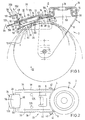
- Fig. 1 einen Vertikalschnitt durch eine erste Ausführungsform einer erfindungsgemäßen Laufrolle,
- Fig. 2 eine Ansicht in Pfeilrichtung II gemäß Fig. 1,
- Fig. 3 eine Ansicht in Pfeilrichtung III gemäß Fig. 1 ohne Laufrad,
- Fig. 4 eine Draufsicht des Feststellhebels in Pfeilrichtung IV gemäß Fig. 1,
- Fig. 5 eine Draufsicht des Lösehebels ebenfalls in Pfeilrichtung IV, gemäß Fig. 1,
- Fig. 6 einen Vertikalschnitt durch eine zweite Ausführungsform einer erfindungsgemäßen Laufrolle,
- Fig. 7 eine Draufsicht des Lösehebels in Pfeilrichtung VII gemäß Fig. 6,
- Fig. 8 eine Draufsicht des Feststellhebels in Pfeilrichtung VII gemäß Fig. 6,
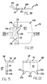
- Fig. 9 einen Vertikalschnitt durch den Bereich der Feststelleinrichtung einer dritten Ausführungsform einer erfindungsgemäßen Laufrolle, wobei Feststell- und Lösehebel einstückig ausgebildet sind,
- Fig. 10 eine Teil-Draufsicht des Feststell-/Lösehebels in Pfeilrichtung X gemäß Fig. 9,
- Fig. 11 eine Draufsicht auf den Blechzuschnitt (Abwicklung) des Feststell-/Lösehebels gemäß Fig. 9 und 10,
- Fig. 12 einen Vertikalschnitt durch den Bereich der Feststelleinrichtung einer weiteren Ausführungsform der erfindungsgemäßen Laufrolle,
- Fig. 13 und 14 gegenüber Fig. 12 verkleinerte Seitenansichten der zwei Teile des in dieser Ausführung zweiteiligen Feststellhebels (in Fig. 14 teilgeschnitten),
- Fig. 15 eine Draufsicht des ersten Teils des Feststellhebels in Pfeilrichtung XV gemäß Fig. 13,
- Fig. 16 eine Draufsicht des zweiten Teils des Feststellhebels in Pfeilrichtung XVI gemäß Fig. 14, wobei die Lage des Teilschnittes von Fig. 14 anhand der Schnittlinie XIV eingezeichnet ist,
- Fig. 17 eine gegenüber Fig. 12 verkleinerte Draufsicht des Lösehebels,
- Fig. 18 einen Schnitt durch den Lösehebel längs der Linie XVIII-XVIII in Fig. 17,
- Fig. 19 eine gegenüber Fig. 12 verkleinerte Seitenansicht des Arretierelementes,
- Fig. 20 eine Ansicht des Arretierelementes in Pfeilrichtung XX gemäß Fig. 19.
- 1 is a vertical section through a first embodiment of a roller according to the invention,
- 2 is a view in the direction of arrow II of FIG. 1,
- 3 is a view in the direction of arrow III of FIG. 1 without impeller,
- Fig. 4 is a plan view of the locking lever in the direction of the arrow IV according to FIG. 1,
- 5 is a plan view of the release lever also in the direction of arrow IV, according to FIG. 1,
- 6 shows a vertical section through a second embodiment of a roller according to the invention,
- 7 is a plan view of the release lever in the direction of arrow VII of FIG. 6,
- 8 is a plan view of the locking lever in the direction of arrow VII of FIG. 6,
- 9 is a vertical section through the area of the locking device of a third embodiment of a roller according to the invention, locking and release levers being formed in one piece,
- 10 is a partial plan view of the locking / release lever in the direction of arrow X according to FIG. 9,
- 11 is a plan view of the sheet metal blank (processing) of the locking / releasing lever according to FIGS. 9 and 10,
- 12 is a vertical section through the area of the locking device of a further embodiment of the roller according to the invention,
- 13 and 14 compared to Fig. 12 reduced side views the two parts of the two-part locking lever in this embodiment (partially cut in FIG. 14),
- 15 is a plan view of the first part of the locking lever in the direction of arrow XV according to FIG. 13,
- 16 is a plan view of the second part of the locking lever in the direction of arrow XVI according to FIG. 14, the position of the partial section of FIG. 14 being drawn in on the section line XIV,
- 17 is a plan view of the release lever that is smaller than that of FIG. 12,
- 18 shows a section through the release lever along the line XVIII-XVIII in FIG. 17,
- 19 is a smaller side view of the locking element compared to FIG. 12,
- 20 is a view of the locking element in the direction of arrow XX according to FIG. 19.
In den verschiedenen Zeichnungsfiguren sind gleiche bzw. gleichwirkende Teile oder Komponenten jeweils mit den gleichen Bezugsziffern bezeichnet.In the various drawing figures, the same or equivalent parts or components are each designated with the same reference numerals.
In der Zeichnung ist beispielhaft eine Lenkrolle 2 dargestellt, jedoch läßt sich die Erfindung ohne weiteres auch bei feststehenden, sogenannten Bockrollen verwirklichen. Die Lenkrolle 2 besteht im wesentlichen aus einem gabelförmigen Rollengehäuse 4 mit einer Gabelbrücke 6 und zwei sich rechtwinklig nach unten daran anschließenden Gabelarmen 8, zwischen denen auf einer Achse 10 ein Laufrad 12 drehbeweglich gelagert ist. In den Fig. 1, 6, 9 und 12 sind jeweils Laufräder 12 mit unterschiedlichen Durchmessern angedeutet. Bei herkömmlichen Laufrädern können Durchmessertoleranzen d von bis zu ± 3 mm auftreten, was bisher bei der Feststellung des Laufrades 12 zu den oben bereits beschriebenen Problemen führte. Diese Probleme werden durch die vorliegenden Erfindung beseitigt, wie dies im folgenden noch erläutert wird.A
Für eine apparateseitige Befestigung besitzt die Lenkrolle 2 in an sich bekannter Weise einen in der Gabelbrücke 6 insbesondere über Wälzlager 14 gelagerten Drehkranz 16, der eine Schwenk- bzw. Lenkbewegung der Lenkrolle 2 um eine vertikale Achse 18 ermöglicht.For attachment on the apparatus side, the
Weiterhin ist an dem Rollengehäuse 4 eine Feststelleinrichtung 20 gelagert, die aus einem schwenkbeweglich gelagerten, federbelasteten, etwa tangential zum Umfang des Laufrades 12 angeordneten Feststellhebel 22 sowie einem schwenkbeweglich gelagerten, federbelasteten, mit dem Feststellhebel 22 zum Arretieren sowie Lösen zusammenwirkenden Lösehebel 24 besteht. Der Feststellhebel 22 ist vorzugsweise durch Fußbetätigung aus einer Losstellung (in Fig. 1 und 6 jeweils gestrichelt sowie in Fig. 9 und 12 voll gezeichnet dargestellt) in eine durch den Lösehebel 24 arretierte Feststellung (in Fig. 1 und 6 voll und in Fig. 9 gestrichelt gezeichnet) bewegbar, in der er mit einem gegen das Laufrad 12 bewegbaren, ein gegen dessen Lauffläche wirkendes Feststellelement 26 aufweisenden, ersten Hebelarm 28 das Laufrad 12 sowie mit einem gegen den Drehkranz 16 bewegbaren, mit einer Verzahnung 30 des Drehkranzes 16 zusammenwirkenden, zweiten Hebelarm 32 auch den Drehkranz 16 feststellt.Furthermore, a
Durch Betätigung des Lösehebels 24 wird die Arretierung des Feststellhebels 22 wieder aufgehoben, so daß dieser sich aufgrund seiner Federbelastung zurück in die Losstellung bewegt.By actuating the
Die Feststelleinrichtung 20 kann unmittelbar an dem Rollengehäuse 4 gelagert sein, wobei der Feststellhebel 22 und der Lösehebel 24 vorzugsweise an der Unterseite der Gabelbrücke 6 befestigt sind.The locking
Bei den dargestellten, bevorzugten Ausführungsformen der Erfindung ist die Feststelleinrichtung 20 jedoch mittelbar über ein gesondertes Feststellergehäuse 34 an dem Rollengehäuse 4 gelagert, wobei der Feststellhebel 22 und der Lösehebel 24 an dem Feststellergehäuse 34 befestigt sind. Das Feststellergehäuse 34 ist erfindungsgemäß im wesentlichen U-förmig aus einer Stegwandung 36 und zwei zu dieser senkrechten Schenkelwandungen 38 gebildet, wobei das Feststellergehäuse 34 das Rollengehäuse 4 bereichsweise übergreift. Dabei liegt die Stegwandung 36 bereichsweise auf der Gabelbrücke 6 auf, und die Schenkelwandungen 38 liegen außen an den Gabelarmen 8 bereichsweise an. Weiterhin besitzt das Feststellergehäuse 34 in den Ausführungen nach Fig. 1 bis 8 erfindungsgemäß eine aus der Stegwandung 36 freigeschnittene oder durch einen U-förmigen Ausschnitt 39 (Fig. 2) freigesparte und aus der Ebene der Stegwandung 36 in Richtung der Schenkelwandungen 38 nach unten herausgebogene, etwa parallel zur Stegwandung 36 unterhalb von dieser angeordnete Haltezunge 40, die die Gabelbrücke 6 des Rollengehäuses 4 untergreift. Die Ausführungsformen nach den Fig. 9 bis 11 sowie nach den Fig. 12 bis 20 unterscheidet sich hiervon etwas in der Art der Halterung des Feststellergehäuses 34, wie dies weiter unten noch erläutert wird. Zur Befestigung der Feststelleinrichtung 20 bzw. des Feststellergehäuses 34 an dem Rollengehäuse 4 besitzen die Gabelarme 8 und die Schenkelwandungen 38 in allen Ausführungen jeweils miteinander fluchtende Durchgangslöcher, durch die sich ein beispielsweise als Schraubbolzen ausgebildeter Befestigungsbolzen 42 hindurch erstreckt und mit einer Mutter 44 verschraubt ist. Alternativ hierzu wäre natürlich auch ein Nietbolzen oder dergleichen verwendbar.In the preferred embodiments of the invention shown, however, the locking
Die Feststelleinrichtung 20 kann dabei in Laufrichtung der Lenkrolle 2 bzw. des Laufrades 12 gesehen alternativ im vor oder hinter der Achse 10 liegenden Bereich angeordnet sein.The locking
In den dargestellten Ausführungsbeispielen der Erfindung verläuft der Lösehebel 24 etwa parallel zu dem ersten Hebelarm 28 des Feststellhebels 22 zwischen diesem und der Gehäuse- bzw. Stegwandung 36. Weiterhin besitzt die Stegwandung 36 in Umfangsrichtung des Laufrades 12 gesehen zwei über einen stumpfen Winkel ineinander übergehende Abschnitte, wodurch sie etwa an die Umfangskontur des Laufrades 12 angepaßt ist (siehe Fig. 1, 6, 9 und 12). Diesem Verlauf ist insbesondere in den Ausführungen gemäß Fig. 6, 9 und 12 auch der Feststellhebel 22 durch eine entsprechend winklige Ausbildung zwischen dem ersten Hebelarm 28 und dem zweiten Hebelarm 32 angepaßt.In the illustrated exemplary embodiments of the invention, the
Mit dem ersten Hebelarm 28 des Feststellhebels 22 ist erfindungsgemäß ein sich etwa senkrecht zu dem Feststellhebel 22 sowie zu dem Lösehebel 24 von dem Laufrad 12 weg erstreckendes und durch eine Gehäuseöffnung 46 der Gehäuse- bzw. Stegwandung 36 geführtes Arretierelement 48 verbunden, welches in den dargestellten Ausführungsbeispielen der Erfindung jeweils aus einem im wesentlichen L-förmig gebogenen Blechstreifen besteht, wobei ein längerer L-Schenkel 50 endseitig vorzugsweise selbstklemmend in eine Öffnung 52 des Feststellhebels 22 bzw. dessen ersten Hebelarmes 28 eingepreßt (Fig. 1 bis 8) oder mit dem Feststellhebel 22 vernietet (Fig. 9 bis 11) ist, sich durch eine Durchgangsöffnung 54 des Lösehebels 24 sowie die Gehäuseöffnung 46 hindurch erstreckt und oberhalb der Gehäuse- bzw. Stegwandung 36 in einen kürzeren, eine oberseitige Trittfläche 56 aufweisenden L-Schenkel 58 übergeht. Erfindungsgemäß ist weiterhin einerseits zwischen dem längeren Schenkel 50 des Arretierelementes 48 und einem Öffnungsrand 60 der Gehäuseöffnung 46 und andererseits zwischen dem längeren Schenkel 50 des Arretierelementes 48 und einer Anlagekante 62 des Lösehebels 24 jeweils ein Kraft- und/oder Formschluß gegeben, wobei der Lösehebel 24 derart schwenkbeweglich gelagert ist, daß sich bei seiner Betätigungsbewegung in Pfeilrichtung 64 gemäß Fig. 1, 6, 9 und 12 die Anlagekante 62 den Kraft- und/oder Formschluß aufhebend von dem Schenkel 50 des Arretierelementes 48 weg bewegt. Hierdurch wird das Arretierelement 48 zusammen mit dem Feststellhebel 22 freigegeben, so daß sich letzterer aus der Feststellung durch Federkraft wieder in die gestrichelt gezeichnete Losstellung zurückbewegen kann. Vorzugsweise ist _ wie dargestellt _ die Anlagekante 62 des Lösehebels 24 von einem Öffnungsrand der von dem längeren Schenkel 50 des Arretierelementes 48 durchgegriffenen Durchgangsöffnung 54 des Lösehebels 24 gebildet.With the
Es ist besonders vorteilhaft, wenn der Feststellhebel 22 und der Lösehebel 24 jeweils aus einstückig ausgestanzten Blattfedern gebildet sind, da sich hierdurch zusätzliche Federelemente erübrigen können.It is particularly advantageous if the locking
Die im ersten Ausführungsbeispiel nach Fig. 1 bis 3 als Feststellhebel 22 und Lösehebel 24 verwendeten Blattfedern sind im Detail in den Figuren 4 und 5 dargestellt.The leaf springs used as locking
Gemäß Fig. 4 besteht der Feststellhebel 22 aus einem einstückigen Stanzteil 65 aus Federblech mit einem den ersten Hebelarm 28 bildenden, im wesentlichen rechteckigen, breiteren Flächenabschnitt 66, der über Schrägkanten 68 in einen schmaleren, den zweiten Hebelarm 32 bildenden Flächenabschnitt 70 übergeht. Im Übergangsbereich zwischen den Schrägkanten 68 und dem schmaleren Flächenabschnitt 70 ist eine Kröpfung 72 (in Fig. 1 erkennbar) derart gebildet, daß im montierten Zustand der erste Hebelarm 28 dem Laufrad 12 näherliegt als der zweite Hebelarm 32. Der schmalere Flächenabschnitt 70 weist einen mittigen, U-förmigen Ausschnitt 74 auf, wobei sich die U-Schenkel 76 dieses Ausschnittes 74 ausgehend von dem im Bereich der Kröpfung 72 liegenden U-Steg 78 in Richtung des freien Endes des zweiten Hebelarmes 32 etwa bis in die Mitte von dessen Länge erstrecken. Durch den Ausschnitt 74 ist eine Befestigungszunge 80 freigespart, die ein etwa mittiges Befestigungsloch 82 aufweist. Diese Befestigungszunge 80 ist z.B. über eine das Befestigungsloch 82 durchgreifende Nietverbindung 84 an der Unterseite der Haltezunge 40 des Feststellergehäuses 34 befestigt (siehe Fig. 1). Durch den U-förmigen Ausschnitt 72 sind weiterhin beidseitig der Befestigungszunge 80 Stege 86 gebildet. Die Befestigungszunge 80 bildet in ihrem zwischen dem Befestigungsloch 82 und ihrem angebundenen Ende liegenden Bereich eine Sollbiegestelle 88 und damit einen Schwenkpunkt für den Feststellhebel 22.4, the locking
Durch eine zur Betätigung des Feststellhebels 22 durchgeführte Verschwenkung des ersten Hebelabschnittes 28 wird diese Schwenkbewegung über die seitlichen Stege 86 derart auf den zweiten Hebelabschnitt 32 übertragen, daß sich der gesamte Feststellhebel 22 wippenartig durch Verbiegung im Bereich der Sollbiegestelle 88 der Befestigungszunge 80 bewegt, d.h. der erste und zweite Hebelabschnitt 28, 32 bewegen sich stets in unterschiedliche Richtungen. Im Endbereich der U-Schenkel 76 des Ausschnittes 74 können diese _ wie in Fig. 4 gestrichelt dargestellt ist _ in aufeinanderzu gerichtete, die Zunge 80 im Bereich der Sollbiegestelle 88 verschmalernde Ausschnitte 90 übergehen, wodurch die Federelastizität bzw. Federkraft der Befestigungszunge 80 bzw. der Sollbiegestelle 88 beeinflußt werden kann. Im freien Endbereich weist der zweite Hebelarm 32 bzw. der schmalere Flächenabschnitt 70 des Stanzteils 65 eine an die Umfangskontur der Verzahnung 30 des Drehkranzes 16 angepaßte, kreisbogenförmige Endkante 92 mit vorzugsweise drei in Umfangsrichtung des Drehkranzes 16 beabstandeten, in der Feststellung in die am Außenumfang einer Kugelhülse 93 des Drehkranzes 16 gebildete Verzahnung 30 eingreifende Arretiernocken 94 auf.By pivoting the
Der breitere Flächenabschnitt 66 des Stanzteils 65 besitzt in seinem dem schmaleren Flächenabschnitt 70 zugekehrten Bereich einen etwa H-förmigen Ausschnitt 96 mit zwei parallelen, in Längsrichtung des Feststellhebels 22 verlaufenden Abschnitten 98 und einem diese im jeweils mittigen Bereich miteinander verbindenden, quer verlaufenden Abschnitt 100. Hierdurch sind zwei in Umfangsrichtung des Laufrades 12 gegenüberliegende, in Richtung der Lauffläche des Laufrades 12 schräg nach unten abgebogene, das Feststellelement 26 bildende Feststellzungen 102 gebildet (siehe auch Fig. 1).The
Weiterhin weist der breitere Flächenabschnitt 66 des Stanzteils 65 in seinem freien Endbereich die Öffnung 52 auf, die hier als ein sich quer zur Hebel-Längsrichtung erstrekkender, rechteckiger Ausschnitt 104 ausgebildet ist, der in zwei parallele, sich in Richtung des schmaleren Flächenabschnittes 70 erstreckende Ausschnitte 106 übergeht, wobei diese beiden Ausschnitte 106 zwischen sich eine Klemmzunge 108 bilden. Dabei ist es wesentlich, daß diese Klemmzunge 108 eine derartige Länge aufweist, daß sie etwas in die Öffnung des rechteckiges Ausschnittes 104 hineinragt. Der rechteckige Ausschnitt 104 entspricht formmäßig etwa dem Querschnitt des längeren L-Schenkels 50 des Arretierelementes 48. Durch diese Ausbildung bewirkt ein Hineindrücken des Endes des L-Schenkels 50 in den rechteckigen Ausschnitt 104 eine selbstklemmende Halterung über die sich leicht federelastisch verbiegende Klemmzunge 108 (siehe hierzu auch Fig. 6).Furthermore, the
Gemäß Fig. 5 besteht der Lösehebel 24 ebenfalls aus einem einstückigen Federblech-Stanzteil 110, welches in diesem Beispiel eine im wesentlichen rechteckige Form besitzt. Im Bereich eines Endes weist das Stanzteil 110 zwei Befestigungslöcher 112 in bezüglich der Längsmittelachse symmetrischer Anordnung auf. Ein Stück von den Befestigungslöchern 112 in Richtung des anderen Endes beabstandet ist ein rechteckiger Ausschnitt 114 angeordnet, wodurch zwei seitliche Randstege 116 gebildet sind, die eine Sollbiegestelle 118 und damit einen Schwenkpunkt für den Lösehebel 24 definieren. Über unterschiedliche Breiten der Stege 116 läßt sich dabei die Federelastizität bzw. die Federkraft beeinflussen.5, the
Das Stanzteil 110 weist weiterhin die durch einen rechteckigen Ausschnitt gebildete Durchgangsöffnung 54 auf, wobei an einem den Ausschnitt 114 von der Durchgangsöffnung 54 trennenden Quersteg 120 eine in die Durchgangsöffnung 54 hineinragende, widerhakenartig schräg etwa in Richtung des Befestigungsbereiches zwischen dem Feststellhebel 22 und dem Ende des längeren Schenkels 50 des Arretierelementes 48 abgebogene Arretierzunge 122 angebunden ist (siehe auch Fig. 1). Am freien Ende der Arretierzunge 122 ist die oben bereits erwähnte Anlagekante 62 gebildet, deren Funktion im folgenden noch erläutert werden wird. Das von den Befestigungslöchern 112 entfernte Ende des Stanzteils 110 bildet einen flachen, endseitig leicht abgerundeten Betätigungsabschnitt 123.The stamped
Der in Fig. 5 dargestellte Lösehebel 24 ist gemäß Fig. 1 bis 3 über zwei die Befestigungslöcher 112 durchgreifende Nietverbindungen 125 an der Unterseite der Stegwandung 36 des Feststellergehäuses 34 befestigt. Unabhängig von dieser Befestigung ist _ wie oben bereits erwähnt _ der in Fig. 4 dargestellte Feststellhebel 22 gemäß Fig. 1 und 3 gesondert über die einzelne Nietverbindung 84 mit der Befestigungszunge 80 an der Unterseite der Haltezunge 40 des Festellergehäuses 34 befestigt. Anstatt der beschriebenen und dargestellten Nietverbindungen sind natürlich ebenfalls beliebige andere Verbindungsmittel oder Verbindungsarten möglich, ohne den Rahmen der Erfindung zu verlassen. Es seien hier beispielsweise Schraubverbindungen und stoffschlüssige Verbindungen (Kleben) genannt.The
Die im zweiten Ausführungsbeispiel nach Fig. 6 als Feststellhebel 22 und Lösehebel 24 verwendeten Blattfedern sind in den Fig. 7 und 8 dargestellt. Diese Blattfedern unterscheiden sich von denjenigen der Fig. 4 und 5 jedoch nur unwesentlich, so daß im folgenden nur kurz auf die Unterschiede eingegangen werden soll. Darüber hinaus sind hier gleiche Teile mit den gleichen Bezugsziffern der übrigen Figuren versehen, so daß auch jeweils auf die obigen Ausführungen hierzu verwiesen werden kann.The leaf springs used in the second embodiment according to FIG. 6 as locking
Gemäß Fig. 7 besteht hier der Lösehebel 24 aus einem einstückigen Federblech-Stanzteil 124 mit einem schmaleren Abschnitt 126, der über Schrägkanten 128 in einen breiteren, das freie Ende des Lösehebels 24 bildenden Abschnitt 130 übergeht. Im Endbereich des schmaleren Abschnittes 126 ist im Gegensatz zur Ausführung nach Fig. 5 nur ein mittig angeordnetes Befestigungsloch 112 gebildet. Ansonsten wird auf die Ausführungen zu Fig. 5 verwiesen.According to FIG. 7, the
Der in Fig. 8 dargestellte, aus einem einstückigen Federblech-Stanzteil 132 bestehende Feststellhebel entspricht in seiner Ausbildung im wesentlichen dem Stanzteil 65 gemäß Fig. 4, wobei er aber _ wie in Fig. 6 erkennbar ist _ über Biegungen noch mehr der Umfangskontur des Laufrades 12 angepaßt ist.The locking lever shown in FIG. 8, consisting of a one-piece spring sheet metal stamping part 132, corresponds essentially in its design to the stamping
In der Ausführung nach Fig. 6 sind der Lösehebel 24 (Fig. 7) und der Feststellhebel 22 (Fig. 8) vorteilhafterweise gehäuseseitig über eine gemeinsame, die Befestigungslöcher 82 und 112 durchgreifende Nietverbindung 134 befestigt, wozu in diesem Fall in einem neben bzw. hinter der Haltezunge 40 liegenden Bereich der Stegwandung 36 des Feststellergehäuses 34 ein entsprechendes Befestigungsloch (nicht bezeichnet) angeordnet ist. Anstatt der Nietverbindung kann natürlich auch hier eine beliebige andere Verbindungsart gewählt werden (Schrauben, stoffschlüssige Verbindung usw.).In the embodiment according to FIG. 6, the release lever 24 (FIG. 7) and the locking lever 22 (FIG. 8) are advantageously fastened on the housing side via a
In der in den Fig. 9 bis 11 dargestellten, besonders vorteilhaften Weiterbildung der Erfindung sind der Feststellhebel 22 und der Lösehebel 24 gemeinsam von einer einzigen, einstückigen Blattfeder gebildet. Diese Blattfeder besteht aus einem in Fig. 11 als "Abwicklung" dargestellten, einstückigen Federblech-Stanzteil 140, das einendig einen schmaleren Endabschnitt 142 und anderendig einen breiteren Endabschnitt 144 aufweist, wobei diese beiden Abschnitte 142, 144 über Schrägkanten 146 ineinander übergehen. Der schmalere Endabschnitt 142 bildet den zweiten Hebelarm 32 des Feststellhebels 22 und weist daher die oben bereits beschriebene, kreisbogenförmige Endkante 92 mit den an dieser angebundenen Arretiernocken 94 auf, wobei allerdings in diesem Beispiel nur zwei Arretiernocken 94 vorgesehen sind. Das dem schmaleren Endabschnitt 142 abgekehrte, freie Ende des breiteren Endabschnittes 144 bildet den Betätigungsabschnitt 123 des Lösehebels 24. Das Stanzteil 140 besitzt etwa in seinem mittigen Bereich einen im wesentlichen U-förmigen Ausschnitt 148 mit zwei zueinander parallelen, zur Hebel-Längsachse symmetrischen, sich von dem Betätigungsabschnitt 123 aus bis über den Bereich der Schrägkanten 146 hinaus ein Stück in den Bereich des schmaleren Endabschnittes 142 hinein erstreckenden Schenkelausschnitten 150, die auf der Seite des Betätigungsabschnittes 123 über einen senkrecht zur Hebel-Längsachse angeordneten Verbindungsausschnitt 142 ineinander übergehen. Durch den U-förmigen Ausschnitt 148 ist somit eine den ersten Hebelarm 28 des Feststellhebels 22 bildende Federzunge 154 freigeschnitten, die in ihrem freien Endbereich einen um eine Biegelinie 156 in Richtung des Laufrades 12 umgebogenen Steg 158 aufweist, der in diesem Ausführungsbeispiel das Feststellelement 26 des Feststellhebels 22 bildet (siehe hierzu auch Fig. 9 und 10). Weiterhin besitzt die Federzunge 154 in ihrem sich an den Steg 158 anschließenden Endbereich die im dargestellten Beispiel als quadratische Befestigungsöffnung 160 ausgebildete Öffnung 52 zum Befestigen (Vernieten) des längeren L-Schenkels 50 des Arretierelementes 48.In the particularly advantageous development of the invention shown in FIGS. 9 to 11, the locking
Durch den U-förmigen Ausschnitt 148 sind weiterhin zwei seitliche Randstege 162 gebildet, über die der Feststellhebel 22 mit dem Lösehebel 24 einstückig verbunden ist. Etwa in seinem mittigen Bereich besitzt jeder der Randstege 162 ein Befestigungsloch 164, wobei die Befestigungslöcher 164 die Grenze zwischen dem Lösehebel 24 und dem Feststellhebel 22 definieren.The
Durch den U-förmigen Ausschnitt 148 ist auch der Lösehebel 24 im wesentlichen U-förmig aus Abschnitten der Randstege 162 und dem diese verbindenden Betätigungsabschnitt 123 ausgebildet. Die Schenkelausschnitte 150 des U-förmigen Ausschnittes 148 erweitern sich im Bereich des Lösehebels 24 kurz vor dem Übergang zu dem Verbindungsausschnitt 152 über nach außen verspringende Stufenkanten 166. Ausgehend von den äußeren Enden der Stufenkanten 166 sind aus den Randstegen 162 durch in Fig. 11 gestrichelt dargestellte, sich in Hebel-Längsrichtung erstreckende Einschnitte 168 zwei Arretierzungen 170 freigeschnitten, die um ebenfalls gestrichelt eingezeichnete Biegelinien 172 abgebogen sind (analog zu der Arretierzunge 122 der Ausführungsbeispiele nach Fig. 1 bis 8). Die nach dem Umbiegen an den freien Enden der Arretierzungen 170 angeordneten Stufenkanten 166 bilden hinsichtlich ihrer Wirkung die _ hier zweigeteilte _ Anlagekante 62 (vgl. die Ausführungsbeispiele nach Fig. 1 bis 8).Due to the
In einem die Arretierzungen 170, die Erweiterung der Schenkelausschnitte 150 und den Verbindungsausschnitt 152 in Hebel-Längsrichtung überdeckenden Bereich besitzt der breitere Endabschnitt 144 des Stanzteils 140 beidseitig jeweils einen randlichen Stegansatz 174 mit einem um eine in Fig. 11 gestrichelt eingezeichnete Biegelinie 176 etwa rechtwinklig umgebogenen Versteifungssteg 178 (siehe auch Fig. 10). Aufgrund dieser Versteifungsstege 178 ist im zwischen diesen und den Befestigungslöchern 164 liegenden Bereich der Randstege 162 jeweils eine Sollbiegestelle 180 und damit ein Schwenkpunkt für den Lösehebel 24 gebildet, wobei in jedem Fall aufgrund der Versteifungsstege 178 sichergestellt ist, daß bei Verschwenkung des Lösehebels 24 über einen Druck auf den Betätigungsabschnitt 123 auch die Arretierzungen 170 "mitgenommen" werden, was für die Funktion der erfindungsgemäßen Feststelleinrichtung von Wichtigkeit ist, wie dies nachfolgend noch erläutert wird.In one the locking
In den dem Lösehebel 24 abgekehrten Bereichen der Randstege 162 sind diese über die Schrägkanten 146 jeweils in einen dem Befestigungsloch 164 zugekehrten, breiteren Abschnitt 182 und einen dem Befestigungsloch 164 abgekehrten, schmaleren Abschnitt 184 unterteilt, wobei in den schmaleren Abschnitten 184 jeweils eine Sollbiegestelle 186 und damit ein Schwenkpunkt für den Feststellhebel 22 gebildet ist, um den sich dieser _ ebenso wie bei den bereits beschriebenen Ausführungen _ wippenartig bewegen kann. Die Abschnitte 182 und 184 der Randstege 162 gehen über derartige Verkröpfungen 188 ineinander über, daß der erste Hebelarm 28 des Feststellhebels 22 in einer Ebene "unterhalb" des Lösehebels 24 angeordnet ist (siehe Fig. 11). Dabei verläuft jeweils ein zwischen zwei Verkröpfungen 188 liegender Abschnitt 189 der Randstege 162 parallel zu der Stegwandung 36 des Feststellergehäuses 34 in einem Abstand von der Stegwandung 36, der etwa der Dicke des Materials der Gabelbrücke 6 entspricht. Zur Halterung des Feststellergehäuses 34 an dem Rollengehäuse 4 untergreifen diese Abschnitte 189 der Randstege 162 die Gabelbrücke 6 etwa analog zu der Haltezunge 40 der Ausführungsbeispiele nach Fig. 1 bis 8. Diese Haltezunge 40 kann sich daher in diesem Ausführungsbeispiel nach Fig. 9 bis 11 vorteilhafterweise erübrigen.In the areas of the
Zur Befestigung des mit dem Lösehebel 24 einstückigen Feststellhebels 22 werden die auf der Unterseite der Stegwandung 36 des Festellergehäuses 34 aufliegenden Randstege 162 im Bereich der Befestigungslöcher 164 mit der Stegwandung 36 vernietet (siehe die Nietverbindung 190 in Fig. 9), oder aber auf andere geeignete Art befestigt (Kleben, Verschrauben).To fasten the locking
Die in den Fig. 12 bis 20 veranschaulichte Ausführungsform der Erfindung entspricht im wesentlichen den bisher beschriebenen Ausführungen, so daß auch hier wiederum gleiche bzw. gleichwirkende Teile die gleichen Bezugsziffern tragen. Es kann hierzu auf die obigen Ausführungen verwiesen werden. Im folgenden sollen nun insbesondere die Unterschiede erläutert werden. In dieser Ausführung besteht der Lösehebel 24 vorteilhafterweise aus einem _ im Gegensatz zu den bisher beschriebenen Blattfeder-Stanzteilen _ formstabilen Blechteil 210 (siehe auch Fig. 17 und 18), welches "schwimmend" zwischen der Stegwandung 36 und dem Feststellhebel 22 gelagert ist. Hierzu besteht das Blechteil 210 aus dem im wesentlichen etwa rechteckigen Betätigungsabschnitt 123 und einer in Richtung der Stegwandung 36 nach oben abgekröpften Lagerzunge 212, die sich _ ein Kipp- oder Schwenklager bildend _ an der Unterseite der Stegwandung 36 abstützt (siehe Fig. 12). Dabei erstreckt sich auch hier das Arretierelement 48 (in den Fig. 19 und 20 dargestellt) mit dem längeren L-Schenkel 50 durch die Durchgangsöffnung 54 des Lösehebels 24 hindurch, wobei gemäß Fig. 17 das Blechteil 210 nach innen in die Durchgangsöffnung 54 ragende Klemmansätze 214 mit in diesem Fall jeweils einer Anlagekante 62 aufweist, die den beschriebenen Kraftschluß zwischen dem Lösehebel 24 und dem Arretierelement 48 verstärken, indem bei verschwenktem bzw. gekipptem Lösehebel 24 das Arretierelement 8 zwischen den gegenüberliegenden Anlagekanten 62 klemmend gehalten wird. Die Halterung des den Lösehebel 24 bildenden Blechteils 210 erfolgt hier somit ausschließlich durch das sich durch die Durchgangsöffnung 54 erstreckende Arretierelement 48.The embodiment of the invention illustrated in FIGS. 12 to 20 essentially corresponds to the embodiments described so far, so that here, too, the same or equivalent parts have the same reference numerals. In this regard, reference can be made to the above explanations. The differences in particular will now be explained below. In this embodiment, the
Weiterhin ist in dieser Ausführung der Feststellhebel 22 vorzugsweise zweiteilig aus zwei Blattfeder-Stanzteilen gebildet, und zwar einem den zweiten Hebelarm 32 mit den Arretiernocken 94 aufweisenden, ersten Stanzteil 216 (siehe auch Fig. 13 und 15) und einem den ersten Hebelarm 28 mit dem Feststellelement 26 bzw. den Feststellzungen 102 bildenden, zweiten Stanzteil 218 (siehe auch Fig. 14 und 16). Hierbei entspricht das erste Stanzteil 216 im wesentlichen dem Stanzteil 140 der Ausführung nach Fig. 9 bis 11, so daß hier auf die obigen Erläuterungen verwiesen werden kann. Unterschiedlich ist hier lediglich, daß einerseits die Federzunge 154 ausschließlich der federelastischen Abstützung des Arretierelementes 48 und damit der Verschwenkung des zweiten Hebelarms 32 um die Sollbiegestellen 186 dient, so daß hier der das Feststellelement 26 bildende Steg 158 der Federzunge 154 entfallen kann. Andererseits gehen hier die Randstege 162 einstückig in zwei seitliche Federzungen 222 über, auf denen sich der Lösehebel 24 bzw. das Blechteil 210 federelastisch abstützt. Hierzu liegen die Federzungen 222 endseitig jeweils im Bereich neben der Durchgangsöffnung 54 unter elastischer Vorspannung an dem Betätigungsabschnitt 123 des Blechteils 210 an. Die Federzunge 154 weist auch hier die Befestigungsöffnung 160 für das Arretierelement 48 auf, allerdings ist hier keine Vernietung zwischen dem Arretierelement 48 und der Federzunge 154 vorgesehen, sondern das Arretierelement 48 erstreckt sich mit einem mittigen, im Querschnitt vorzugsweise quadratischen Lagerzapfen 223 des längeren L-Schenkels 50 (siehe Fig. 20) mit geringem Umfangsspiel in die Befestigungsöffnung 160 hinein, wodurch geringfügige Bewegungen zwischen der Federzunge 154 und dem Arretierelement 48 möglich sind, was die Klemmwirkung zwischen dem Lösehebel 24 und dem Arretierelement 48 vorteilhafterweise günstig beeinflußt.Furthermore, in this embodiment, the locking
Das zweite Stanzteil 218 ist erfindungsgemäß lösbar an dem ersten Stanzteil 216 gehaltert, und zwar auf dessen dem Laufrad 12 zugekehrter Seite. Hierzu besitzt das zweite Stanzteil 218 an einer Schmalseite eines rechteckigen Hauptteils 224 eine im stumpfen Winkel nach oben, in Richtung des ersten Stanzteils 216 abgebogene Haltezunge 226 (Fig. 14 und 16), die in eine im sich an die Endkante 92 anschließenden Bereich gebildete Schlitzöffnung 228 des ersten Stanzteils 216 (siehe Fig. 15) kraft- und/oder formschlüssig eingreift, wie dies gut in Fig. 12 zu erkennen ist. Ferner besitzt das zweite Stanzteil 218 zwei seitliche, zueinander parallele, etwa im mittleren Bereich des Hauptteils 224 an dessen Längskanten einstückig angeformte, von der Haltezunge 226 weg weisende Haltestege 230, die im montierten Zustand in seitliche Ausnehmungen 232 (siehe Fig. 20) im Endbereich des längeren Schenkels 50 des Arretierelementes 48 eingreifen. Hierdurch haltern sich das Arretierelement 48 und das zweite Stanzteil 218 vorteilhafterweise praktisch gegenseitig, denn ein "Herausrutschen" des Arretierelementes 48 nach oben wird erfindungsgemäß durch die in die Ausnehmungen 232 eingreifenden Haltestege 230 verhindert. Der der Haltezunge 226 gegenüberliegende Bereich des Hauptteils 224 des zweiten Stanzteils 218 bildet den ersten Hebelarm 28 des Feststellhebels 22 und weist daher das wiederum durch freigesparte und abgebogene Feststellzungen 102 gebildete Feststellelement 26 auf. Da das zweite Stanzteil 218 in diesem Bereich an der Federzunge 154 des ersten Stanzteils 216 anliegt (in Fig. 12 zu erkennen), ist das Feststellelement 26 zum Feststellen des Laufrades 12 in einer zu diesem etwa radialen Richtung mittels des Arretierelementes 48 bewegbar.According to the invention, the second stamped
Wie in Fig. 20 weiterhin zu erkennen ist, besitzt das Arretierelement 48 am freien Ende des längeren Schenkels 50 zwei seitliche Schrägflächen 234, deren Funktion im folgenden noch erläutert werden wird.As can also be seen in FIG. 20, the locking
Bei der Ausführungsform der Fig. 12 bis 20 erfolgt nun die Montage der Feststelleinrichtung 20 wie folgt. Das erste Stanzteil 216 wird über die Nietverbindungen 190 an der Unterseite der Stegwandung 36 befestigt. Nachfolgend wird der Lösehebel 24 bzw. das Blechteil 210 mit der Lagerzunge 212 voraus zwischen die Stegwandung 36 und die Federzunge 154 der ersten Stanzteils 216 geführt, bis die Durchgangsöffnung 54 etwa mit der Öffnung 46 der Stegwandung 36 fluchtet, so daß dann das Arretierelement 48 mit seinem längeren Schenkel 50 durch die beiden Öffnungen hindurch gesteckt werden kann. Dabei greift der Lagerzapfen 223 in die Befestigungsöffnung 160 der Federzunge 154 ein. Schließlich erfolgt die Montage des zweiten Stanzteils 218, indem dieses zunächst mit der Haltezunge 226 in die Schlitzöffnung 228 des ersten Stanzteils 216 eingesteckt wird. Nachfolgend wird das gegenüberliegende Ende des Stanzteils 218 in Richtung des ersten Stanzteils 216 bewegt, bis die seitlichen Haltestege 230 auf die Schrägflächen 234 des längeren Schenkels 50 des Arretierelementes 48 auftreffen und hierdurch federelastisch nach außen gedrängt werden, bis sie in die seitlichen Ausnehmungen 232 einschnappen. Eine Demontage ist vorteilhafterweise ebenso leicht in umgekehrter Reihenfolge möglich.In the embodiment of FIGS. 12 to 20, the locking
Im folgenden sollen nun die Wirkungsweise sowie weitere vorteilhafte Merkmale der erfindungsgemäßen Feststelleinrichtung 20 erläutert werden.The mode of operation and further advantageous features of the
Die Arretierzunge 122 des Lösehebels 24 wirkt mit ihrer Anlagekante 62 im Ausführungsbeispiel nach Fig. 6 kraftschlüssig, d.h. reibend, mit der Oberfläche des längeren Schenkels 50 des Arretierelementes 48 zusammen. In der Ausführung nach Fig. 1 bis 5 weist das Arretierelement 48 erfindungsgemäß auf der der Anlagekante 62 des Lösehebels 24 zugekehrten Oberfläche des längeren L-Schenkels 50 eine Kerbverzahnung 192 auf, in die die Anlagekante 62 der Arretierzunge 122 des Lösehebels 24 form- oder kraftformschlüssig eingreift. Schließlich wirken auch einerseits in der Ausführung nach Fig. 9 bis 11 die die Anlagekante 62 bildenden Stufenkanten 166 der Arretierzungen 170 sowie andererseits in der Ausführung nach Fig. 12 bis 20 die Anlagekanten 62 der Klemmansätze 214 des den Lösehebel 24 bildenden Blechteils 210 jeweils kraftschlüssig, d.h. reibend mit dem Arretierelement 48 zusammen.The locking
In allen Fällen ist in der Feststellung zwischen dem Arretierelement 48 bzw. dessen L-Schenkel 50 und dem auf der der Anlagekante 62 abgekehrten Seite des Arretierelementes 48 an diesem anliegenden Öffnungsrand 60 der Gehäuseöffnung 46 ein Kraftschluß (Reibung) vorhanden. Dies resultiert daraus, daß der L-Schenkel 50 des Arretierelementes 48 erfindungsgemäß in zwei Punkten exakt geführt ist, nämlich einerseits durch die Verbindung mit dem ersten Hebelarm 28 des Feststellhebels 22 und andererseits durch die Gehäuseöffnung 46. Hierdurch kann der Lösehebel 24 mit der Anlagekante 62 unter Vorspannung gegen den Schenkel 50 des Arretierelementes 48 "drücken", ohne daß letzterer ausweichen könnte. Diese Vorspannung bzw. Anlagekraft des Lösehebels 24 über die Anlagekante 62 wird dabei vorteilhafterweise noch erhöht, je weiter der erste Hebelarm 28 "gespannt", d.h. in die Feststellung gebracht wird, denn bei der Verschwenkung des Hebelarms 28 bewegt sich das mit ihm verbundene Arretierelement 48 in Richtung der Anlagekante 62, weil sich ja das freie Ende des Hebelarmes 28 auf einer Kreisbahn um dessen Schwenkpunkt (Sollbiegestelle 88 bzw. 186) bewegt.In all cases, the determination between the locking
Durch die erfindungsgemäße Ausgestaltung ist der Feststellhebel 22 über das Arretierelement 48 vorteilhafterweise in nahezu jeder Stellung über seinen Hebelweg hinweg arretierbar, so daß stets auch bei unterschiedlichen Laufrädern 12 eine Feststellung erreicht werden kann, in der das Laufrad 12 sicher festgestellt ist.Due to the design according to the invention, the locking
In allen Ausführungsbeispielen liegt der zweite Hebelarm 32 des Feststellhebels 22 in seiner den Drehkranz 16 arretierenden Feststellung vorzugsweise an einem gehäuseseitigen Anschlag 194 an (siehe Fig. 1, 6, 9 und 12). Dieser Anschlag 194 kann durch die unterseitige(n) Oberfläche(n) der Gabelbrücke 6 des Rollengehäuses 4 (Fig. 1, 9 und 12) und/oder der Haltezunge 40 des Feststellergehäuses 34 (Fig. 6) gebildet sein. Diese Ausgestaltung ist insofern von Vorteil, als _ sobald der Drehkranz 16 von einer bestimmten Stellung des Feststellhebels 22 bzw. des Arretierelementes 48 ab arretiert ist _ nachfolgend der erste Hebelarm 28 des Feststellhebels 22 zur sicheren Feststellung des Laufrades 12 weitergehend "nachgespannt" werden kann, ohne die Feststellung des Drehkranzes 16 zu beeinflussen, da bei einem derartigen "Nachspannen" der zweite Hebelarm aufgrund der Federelastizität in Anlage an dem Anschlag 194 und damit in der den Drehkranz 16 feststellenden Stellung bleibt.In all of the exemplary embodiments, the
Die das Feststellelement 26 bildenden Feststellzungen 102 (Fig. 1 bis 8 sowie Fig. 12 bis 20) bzw. der Steg 158 (Fig. 9 bis 11) kommen in der Feststellung jeweils mit ihren freien Endkanten zur Auflage auf der Lauffläche des Laufrades 12. Hierdurch ist auch unabhängig von einer etwaigen Profilierung des Laufrades 12 eine sichere Feststellung stets gewährleistet.The locking
Der Lösehebel 24 erstreckt sich vorzugsweise mit dem Betätigungsabschnitt 123 über den Feststellhebel 22 sowie auch über den kürzeren L-Schenkel 58 des Arretierelementes 48 hinaus nach vorne, wobei an dem Betätigungsabschnitt 123 zweckmäßigerweise ein kappenartiger Überzug 196, der nur in Fig. 1, 3, 5, 6 und 7 jeweils gestrichelt angedeutet sowie in Fig. 9 geschnitten dargestellt ist, befestigt ist. Dieser Überzug 196 kann beispielsweise durch eine Kunststoffbeschichtung gebildet sein. Durch seitliche Ausnehmungen 198 des Betätigungsabschnittes 123, wie sie in Fig. 10 und 11 beispielhaft dargestellt sind, sowie ggf. durch Ausnehmungen im Flächenbereich des Betätigungsabschnittes 123 (nicht dargestellt) kann ein Formschluß und damit eine gute Halterung des Überzuges 196 erreicht werden.The
Bei der Ausführung nach Fig. 12 bis 20 ist von besonderem Vorteil, daß der Lösehebel 24 durch die Ausbildung als formstabiles Blechteil eine im Vergleich zu den Blattfedern erhöhte Stabilität besitzt, so daß ein Lösen aus der Feststellung heraus vorteilhafterweise auch gegen sehr hohe Klemmkräfte problemlos möglich ist.In the embodiment according to FIGS. 12 to 20, it is particularly advantageous that the
In einer in der Zeichnung nicht dargestellten Weiterbildung der Erfindung ist die Feststelleinrichtung 20 mit einer insbesondere akustischen Signaleinrichtung ausgestattet, die bei einer bestimmten Mindest-Feststellkraft ein akustisches Signal, z.B. ein Knackgeräusch, erzeugt. Der Benutzer der erfindungsgemäßen Laufrolle erhält hierdurch stets eine Information, ob das Laufrad 12 auch tatsächlich hinreichend festgestellt ist.In a further development of the invention, not shown in the drawing, the locking
Im folgenden soll noch einmal kurz zusammengefaßt die Funktion der erfindungsgemäßen Laufrolle hinsichtlich der Feststelleinrichtung erläutert werden. Aus der Losstellung heraus wird der Feststellhebel 22 durch Fußbetätigung des Arretierelementes 48, d.h. durch Druck in Pfeilrichtung 200 auf die Trittfläche 56 des L-Schenkels 58, in die Feststellung verschwenkt, in der der erste Hebelarm 28 mit dem Feststellelement 26, d.h. den Feststellzungen 102 bzw. dem Steg 158, auf der Lauffläche des Laufrades 12 aufliegt und der zweite Hebelarm 32 mit den Arretiernocken 94 in die Verzahnung 30 des Drehkranzes 16 eingreift. Dabei bewirkt der mit der Anlagekante 62 kraft- und/oder formschlüssig an dem Schenkel 50 des Arretierelementes 48 anliegende Lösehebel 24 auch einen Kraftschluß zwischen dem Arretierelement 48 und dem Öffnungsrand 60 der Gehäuseöffnung 46 und damit eine Arretierung des Feststellhebels 22 über das Arretierelement 48. Zum Lösen dieser Arretierung braucht lediglich der Lösehebel 24 in Pfeilrichtung 64 verschwenkt zu werden, was vorteilhafterweise ebenfalls durch Fußbetätigung erfolgen kann, wobei diese Schwenkbewegung bewirkt, daß sich die Anlagekante 62 des Lösehebels 24 von dem Arretierelement 48 weg bewegt, so daß auch der Kraftschluß zwischen dem Arretierelement 48 und dem Öffnungsrand 60 aufgehoben wird. Der Feststellhebel 22 kann sich hierdurch aufgrund seiner Federelastizität wieder in die Losstellung zurückbewegen, wobei der L-Schenkel 50 des Arretierelementes 48 sich frei durch die Durchgangsöffnung 54 des Lösehebels 24 sowie durch die Gehäuseöffnung 46 hindurch in Pfeilrichtung 202 nach oben bewegen kann.In the following, the function of the roller according to the invention with respect to the locking device will be briefly summarized. From the release position, the locking
Aufgrund der beschriebenen, erfindungsgemäßen Ausgestaltung ist die Lauf- bzw. Lenkrolle 2 der Erfindung vorteilhafterweise konstruktiv äußerst einfach aufgebaut und dadurch auch preiswert herzustellen und zu montieren. Dabei sind insbesondere aufgrund der Ausbildung des Feststellhebels 22 und des Lösehebels 24 jeweils als einteilige bzw. als gemeinsam einteilige Blattfeder(n) keinerlei Lagerstellen erforderlich, sondern die Schwenkbeweglichkeit dieser Hebel wird allein durch ihre Federelastizität in den Sollbiegestellen erreicht.On the basis of the described configuration according to the invention, the running or steering
Die Erfindung ist keineswegs auf die beschriebenen und dargestellten Ausführungsbeispiele beschränkt, sondern umfaßt auch alle im Sinne der Erfindung gleichwirkenden Ausführungsformen, soweit sie in den Ansprüchen definiert sind. Insbesondere soll noch einmal darauf hingewiesen werden, daß die Feststelleinrichtung 20 auch unmittelbar an dem Rollengehäuse 4 gelagert sein kann, wobei der Feststellhebel 22 und der Lösehebel 24 in diesem Fall an dem Rollengehäuse 4 befestigt wären und die Gehäuseöffnung 46 in der Gabelbrücke 6 gebildet wäre. Ferner kann das Feststellelement 26 anstelle der zungenartigen Ausgestaltung auch jede beliebige andere, z.B. ballige Form aufweisen oder auch als ggf. separater "Feststellschuh" ausgebildet sein. Weiterhin kann die in den Patentansprüchen definierte Erfindung ohne weiteres auch bei solchen Laufrollen angewendet werden, bei denen die Feststelleinrichtung ausschließlich als Richtungsfeststeller zum Feststellen des Drehkranzes ausgebildet ist. Hierzu entfällt lediglich das Feststellelement 26 (Feststellzungen 102, Steg 158) des ersten Hebelarmes 28 des Feststellhebels 22, und gegebenenfalls wird eine andere Verzahnung 30 am Drehkranz 16 in Verbindung mit einer modifizierten Ausbildung der Arretiernocken 94 des zweiten Hebelarmes 32 des Feststellhebels 22 vorgesehen. Es ist dann eine Richtungsfixierung der Lenkrolle 2 ohne Radfeststellung möglich (Geradeauslauf).The invention is in no way limited to the exemplary embodiments described and illustrated, but also encompasses all embodiments having the same effect within the meaning of the invention, insofar as they are defined in the claims. In particular, it should be pointed out once again that the locking
Claims (21)
Priority Applications (1)
| Application Number | Priority Date | Filing Date | Title |
|---|---|---|---|
| AT89121662T ATE62872T1 (en) | 1988-11-25 | 1989-11-23 | ROLLER WITH LOCKING DEVICE. |
Applications Claiming Priority (2)
| Application Number | Priority Date | Filing Date | Title |
|---|---|---|---|
| DE3839842A DE3839842A1 (en) | 1988-11-25 | 1988-11-25 | ROLLER WITH LOCKING DEVICE |
| DE3839842 | 1988-11-25 |
Publications (2)
| Publication Number | Publication Date |
|---|---|
| EP0370505A1 EP0370505A1 (en) | 1990-05-30 |
| EP0370505B1 true EP0370505B1 (en) | 1991-04-24 |
Family
ID=6367893
Family Applications (1)
| Application Number | Title | Priority Date | Filing Date |
|---|---|---|---|
| EP89121662A Expired - Lifetime EP0370505B1 (en) | 1988-11-25 | 1989-11-23 | Castor with a locking device |
Country Status (3)
| Country | Link |
|---|---|
| EP (1) | EP0370505B1 (en) |
| AT (1) | ATE62872T1 (en) |
| DE (2) | DE3839842A1 (en) |
Families Citing this family (5)
| Publication number | Priority date | Publication date | Assignee | Title |
|---|---|---|---|---|
| US5328000A (en) * | 1991-10-29 | 1994-07-12 | Saf-T-Loc, Inc. | Foot actuated wheel brake |
| US5383536A (en) * | 1991-10-29 | 1995-01-24 | Saf-T-Loc, Inc. | Foot actuated wheel brake |
| FR2688741B1 (en) * | 1992-03-23 | 1998-06-12 | Guittel Etienne Mobilor | PIVOTING CASTER FOR TROLLEY. |
| NL1023573C2 (en) * | 2003-05-30 | 2004-12-01 | Colson Transportwielen B V | Caster wheel. |
| DE102016110300B4 (en) * | 2016-06-03 | 2019-04-18 | Fechtel Transportgeräte GmbH | Lenkrollenbaueinheit |
Family Cites Families (2)
| Publication number | Priority date | Publication date | Assignee | Title |
|---|---|---|---|---|
| US4110866A (en) * | 1977-11-30 | 1978-09-05 | Sugatsune Industrial Co., Ltd. | Caster equipped with a stopper |
| DE3618448A1 (en) * | 1986-04-08 | 1987-10-22 | Loh Kg Rittal Werk | Castor which can be decelerated and is intended for a load-receiving, moveable supporting plate |
-
1988
- 1988-11-25 DE DE3839842A patent/DE3839842A1/en not_active Withdrawn
-
1989
- 1989-11-23 DE DE8989121662T patent/DE58900096D1/en not_active Expired - Fee Related
- 1989-11-23 AT AT89121662T patent/ATE62872T1/en not_active IP Right Cessation
- 1989-11-23 EP EP89121662A patent/EP0370505B1/en not_active Expired - Lifetime
Also Published As
| Publication number | Publication date |
|---|---|
| DE58900096D1 (en) | 1991-05-29 |
| EP0370505A1 (en) | 1990-05-30 |
| DE3839842A1 (en) | 1990-05-31 |
| ATE62872T1 (en) | 1991-05-15 |
Similar Documents
| Publication | Publication Date | Title |
|---|---|---|
| WO2005083275A1 (en) | Clip-on or snap-on fixing for fastening a thin wall to a wall support | |
| AT2249U1 (en) | HAND STAMP WITH SELF-COLORING DEVICE | |
| DE3910154C2 (en) | Leaf spring arrangement for holding down the brake pad carrier in a disc brake | |
| WO1991015685A1 (en) | Brake cable fixing for a parking brake, especially for a duo-servo chamber hand-brake | |
| EP0370505B1 (en) | Castor with a locking device | |
| DE3829109C2 (en) | Electrical switches, in particular steering column switches for motor vehicles | |
| EP4098526A1 (en) | Frame lock | |
| DE4437620B4 (en) | thermostat | |
| EP2026976A1 (en) | Stamp insert | |
| EP2297760B1 (en) | Rocker switch | |
| EP0754827A2 (en) | Device for releasable and non-sliding of a handle on a bearing element, especially for door handles or window handles | |
| DE19836454C2 (en) | Braked castor for apparatus, devices, furniture or the like | |
| DE3222859A1 (en) | Brake shoe arrangement | |
| EP0730077B1 (en) | Cover holder on covers for door closer cases | |
| DE102006059096B4 (en) | Assembly for vehicle-mounted fastening of a buckle | |
| DE19652027C2 (en) | Mounting rail for fastening pipes or the like | |
| CH671648A5 (en) | Electric contact device for keyboard switch - uses double armed contact element between pushbutton operating element and fixed counter contact pin | |
| DE10032668B4 (en) | Friction disc clutch with an adjusting device to compensate for friction surface wear | |
| DE2726608C2 (en) | Pressure-dependent electrical switching device | |
| DE3031345C2 (en) | ||
| WO1998016404A1 (en) | Notching mechanism for maintaining a control system, particularly a brake system, in case of a collision | |
| DE1413846A1 (en) | Arrangement in program control units for washing machines to run over program sections in high speed | |
| DE3109237A1 (en) | Device for the temporary clamping of material | |
| EP1534541B1 (en) | Steering roller | |
| DE1640851B1 (en) | ELECTRIC PUSH BUTTON WITH A GUIDE SLEEVE |
Legal Events
| Date | Code | Title | Description |
|---|---|---|---|
| PUAI | Public reference made under article 153(3) epc to a published international application that has entered the european phase |
Free format text: ORIGINAL CODE: 0009012 |
|
| AK | Designated contracting states |
Kind code of ref document: A1 Designated state(s): AT BE CH DE ES FR GB GR IT LI LU NL SE |
|
| 17P | Request for examination filed |
Effective date: 19900518 |
|
| 17Q | First examination report despatched |
Effective date: 19900810 |
|
| EL | Fr: translation of claims filed | ||
| ITCL | It: translation for ep claims filed |
Representative=s name: ORGANIZZAZIONE D'AGOSTINI |
|
| GRAA | (expected) grant |
Free format text: ORIGINAL CODE: 0009210 |
|
| AK | Designated contracting states |
Kind code of ref document: B1 Designated state(s): AT BE CH DE ES FR GB GR IT LI LU NL SE |
|
| PG25 | Lapsed in a contracting state [announced via postgrant information from national office to epo] |
Ref country code: SE Effective date: 19910424 Ref country code: NL Effective date: 19910424 Ref country code: GR Free format text: LAPSE BECAUSE OF FAILURE TO SUBMIT A TRANSLATION OF THE DESCRIPTION OR TO PAY THE FEE WITHIN THE PRESCRIBED TIME-LIMIT Effective date: 19910424 Ref country code: GB Effective date: 19910424 Ref country code: ES Free format text: THE PATENT HAS BEEN ANNULLED BY A DECISION OF A NATIONAL AUTHORITY Effective date: 19910424 Ref country code: BE Effective date: 19910424 |
|
| REF | Corresponds to: |
Ref document number: 62872 Country of ref document: AT Date of ref document: 19910515 Kind code of ref document: T |
|
| REF | Corresponds to: |
Ref document number: 58900096 Country of ref document: DE Date of ref document: 19910529 |
|
| ET | Fr: translation filed | ||
| ITF | It: translation for a ep patent filed |
Owner name: ORGANIZZAZIONE D'AGOSTINI |
|
| NLV1 | Nl: lapsed or annulled due to failure to fulfill the requirements of art. 29p and 29m of the patents act | ||
| GBV | Gb: ep patent (uk) treated as always having been void in accordance with gb section 77(7)/1977 [no translation filed] | ||
| PG25 | Lapsed in a contracting state [announced via postgrant information from national office to epo] |
Ref country code: AT Effective date: 19911123 |
|
| PG25 | Lapsed in a contracting state [announced via postgrant information from national office to epo] |
Ref country code: LU Free format text: LAPSE BECAUSE OF NON-PAYMENT OF DUE FEES Effective date: 19911130 Ref country code: LI Effective date: 19911130 Ref country code: CH Effective date: 19911130 |
|
| PLBE | No opposition filed within time limit |
Free format text: ORIGINAL CODE: 0009261 |
|
| STAA | Information on the status of an ep patent application or granted ep patent |
Free format text: STATUS: NO OPPOSITION FILED WITHIN TIME LIMIT |
|
| 26N | No opposition filed | ||
| REG | Reference to a national code |
Ref country code: CH Ref legal event code: PL |
|
| PGFP | Annual fee paid to national office [announced via postgrant information from national office to epo] |
Ref country code: DE Payment date: 19921106 Year of fee payment: 4 |
|
| PGFP | Annual fee paid to national office [announced via postgrant information from national office to epo] |
Ref country code: FR Payment date: 19921116 Year of fee payment: 4 |
|
| ITPR | It: changes in ownership of a european patent |
Owner name: CESSIONE;HEINRICH BLICKLE GMBH & CO. KG |
|
| REG | Reference to a national code |
Ref country code: FR Ref legal event code: TP |
|
| PG25 | Lapsed in a contracting state [announced via postgrant information from national office to epo] |
Ref country code: FR Effective date: 19940729 |
|
| PG25 | Lapsed in a contracting state [announced via postgrant information from national office to epo] |
Ref country code: DE Effective date: 19940802 |
|
| REG | Reference to a national code |
Ref country code: FR Ref legal event code: ST |
|
| PG25 | Lapsed in a contracting state [announced via postgrant information from national office to epo] |
Ref country code: IT Free format text: LAPSE BECAUSE OF NON-PAYMENT OF DUE FEES;WARNING: LAPSES OF ITALIAN PATENTS WITH EFFECTIVE DATE BEFORE 2007 MAY HAVE OCCURRED AT ANY TIME BEFORE 2007. THE CORRECT EFFECTIVE DATE MAY BE DIFFERENT FROM THE ONE RECORDED. Effective date: 20051123 |