EP0368177A2 - Procédé et dispositif de fabrication de plaques d'impression en creux - Google Patents
Procédé et dispositif de fabrication de plaques d'impression en creux Download PDFInfo
- Publication number
- EP0368177A2 EP0368177A2 EP89120427A EP89120427A EP0368177A2 EP 0368177 A2 EP0368177 A2 EP 0368177A2 EP 89120427 A EP89120427 A EP 89120427A EP 89120427 A EP89120427 A EP 89120427A EP 0368177 A2 EP0368177 A2 EP 0368177A2
- Authority
- EP
- European Patent Office
- Prior art keywords
- substance
- gravure
- intaglio printing
- transfer belt
- image
- Prior art date
- Legal status (The legal status is an assumption and is not a legal conclusion. Google has not performed a legal analysis and makes no representation as to the accuracy of the status listed.)
- Granted
Links
Images

Classifications
-
- B—PERFORMING OPERATIONS; TRANSPORTING
- B41—PRINTING; LINING MACHINES; TYPEWRITERS; STAMPS
- B41C—PROCESSES FOR THE MANUFACTURE OR REPRODUCTION OF PRINTING SURFACES
- B41C1/00—Forme preparation
- B41C1/003—Forme preparation the relief or intaglio pattern being obtained by imagewise deposition of a liquid, e.g. by an ink jet
-
- B—PERFORMING OPERATIONS; TRANSPORTING
- B41—PRINTING; LINING MACHINES; TYPEWRITERS; STAMPS
- B41C—PROCESSES FOR THE MANUFACTURE OR REPRODUCTION OF PRINTING SURFACES
- B41C1/00—Forme preparation
- B41C1/055—Thermographic processes for producing printing formes, e.g. with a thermal print head
-
- B—PERFORMING OPERATIONS; TRANSPORTING
- B41—PRINTING; LINING MACHINES; TYPEWRITERS; STAMPS
- B41N—PRINTING PLATES OR FOILS; MATERIALS FOR SURFACES USED IN PRINTING MACHINES FOR PRINTING, INKING, DAMPING, OR THE LIKE; PREPARING SUCH SURFACES FOR USE AND CONSERVING THEM
- B41N3/00—Preparing for use and conserving printing surfaces
- B41N3/003—Preparing for use and conserving printing surfaces of intaglio formes, e.g. application of a wear-resistant coating, such as chrome, on the already-engraved plate or cylinder; Preparing for reuse, e.g. removing of the Ballard shell; Correction of the engraving
-
- B—PERFORMING OPERATIONS; TRANSPORTING
- B41—PRINTING; LINING MACHINES; TYPEWRITERS; STAMPS
- B41P—INDEXING SCHEME RELATING TO PRINTING, LINING MACHINES, TYPEWRITERS, AND TO STAMPS
- B41P2227/00—Mounting or handling printing plates; Forming printing surfaces in situ
- B41P2227/70—Forming the printing surface directly on the form cylinder
Definitions
- the invention relates to a method and a device for producing an intaglio printing plate according to the preamble of claims 1 and 8, respectively.
- the invention has for its object to develop a method and an apparatus for producing a gravure printing plate, by means of which the same can be produced extremely economically.
- the gravure printing plate can be imaged directly in the printing press using the method and the device according to the invention. Forme cylinder transport devices are therefore completely eliminated.
- the Gravure printing plate produced according to the invention can be easily deleted in the printing press and prepared for a new image.
- Fig. 1, 1 is a printing form cylinder of a rotogravure rotary printing machine.
- a pixel transfer unit 2 can be set on the latter, which in this case has a guide bar 3 arranged parallel to a surface line of the printing form cylinder and a print head 4 which can be moved along the latter.
- the print head 4 is provided with at least one nozzle, through which a solid substance that can be liquefied under the influence of heat is sprayed out under pressure.
- the timing and quantity of the spraying out is controlled analogously to the inkjet principle of an inkjet printer by a control unit 5, which reads, via a signal line 6, digitally coded data corresponding to a printed image from an image memory (not shown).
- the substance is transferred point by line line by line, and if several nozzles offset in the circumferential direction of the printing form cylinder 1 are used, several lines can be written in parallel.
- the depth of information - which corresponds to the range of variation with regard to the amount of substance transferred - is preferably 1 byte per pixel, ie 256 possible color gradations.
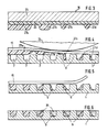
- the surface of the printing form cylinder 1 is provided as a gravure blank with a basic cell grid (see FIG. 3) which is formed from small cells 7 and webs 8 arranged between them.
- the depth of the wells 7 is selected so that they can accommodate at least the maximum amount of paint to be transferred.
- each well 7 only fills with a quantity of ink which corresponds to the volume of the well in the case of the rotogravure raw form minus the volume of the layer 9 (see FIG. 6).
- the inking takes place in a known manner by means of a height-adjustable ink box 10, in which a part of the printing form cylinder 1 is immersed in the raised state.
- Excess ink is scraped off by a squeegee 11 which can be set on the printing form cylinder 1 and is supported on the webs 8, and is conveyed back into the ink fountain 10.
- the printed image is transferred from the cells to a printing material web 12 in accordance with their color filling transferred, which is guided around a printing cylinder 13 and is pressed by this to the printing form cylinder 1.
- a transfer belt 15 is arranged between a pixel transfer unit 14 and the printing form cylinder 1.
- the pixel transmission unit 14 is composed of a guide bar 16 arranged transversely to the transfer belt 15, a thermal print head 17 which can be moved along this and equipped with at least one heatable element, and a transfer film 18 arranged between the latter and the transfer belt 15.
- the transfer film 18 is on its side Transfer belt 15 facing underside coated with a solid, meltable substance when exposed to heat. It is wound up on a drum 19 and, after each line by which the transfer belt 15 is moved, is transported in synchronism with the latter, the used part of the transfer film being wound onto a drum 20.
- a different amount of the substance is melted and deposited on the transfer belt 15 by the heating element (s) of the thermal print head 17 in accordance with digitally coded image information read out by a control unit 21 from an image memory (not shown).
- the substance is transferred point by line line by line, it being possible for several lines to be written in parallel when using a plurality of elements offset in the circumferential direction of the transfer belt 15.
- the information depth - which corresponds to the range of variation with regard to the amount of substance transferred - is preferably 1 byte per pixel, i.e. 256 possible color gradations. It is achieved by varying the intensity of the heating and the contact pressure of the heating elements.
- the transfer belt 15 is brought over a plurality of deflecting rollers 22 to the printing form cylinder 1 so that it is on part of it Circumferential.
- an image delivery device 23 is arranged which, by the action of energy on the back of the transfer belt 15, causes the substance parts to melt again and transfer them to the printing form cylinder 1.
- the image delivery unit 23 is preferably formed by a heatable roller 24, which can be adjusted to the back of the transfer belt 15 with adjustable pressure.
- the transfer of the substance from the transfer ribbon 15 to the printing form cylinder 1 takes place line by line or even flat and is therefore considerably faster than the selective transfer by the thermal print head to the transfer ribbon.
- the decoupling of the slower writing of the transfer belt 15 from the much faster delivery of the substance stored there to the printing form cylinder 1 brings considerable time advantages in production: after completion of a printing form, the transfer belt 15 can be switched off from the printing form cylinder 1 during production and already with a substance application for that next required print image can be provided. With the appropriate length of the transfer belt, all the print images required for shift or daily production can also be stored there in advance and thus temporarily stored.
- the transfer belt 15 is made up of two layers: a backing layer 25 which is very tensile in the longitudinal direction and is dimensionally stable and a non-stick layer 26 which is firmly connected thereto and which preferably consists of polytetrafluoroethylene (PTFE).
- PTFE polytetrafluoroethylene
- the substance parts 27 a, 27 b, 27 c, 27 d ... released by the pixel transfer unit 14 from the transfer film 18 are deposited.
- the transfer belt 15 is pressed with its substance parts 27 a, ..., 27 d ... underside of the roller 24 against the surface of the printing form cylinder 1, melted by the action of energy on the back of the transfer belt 15 and in the Cell base grid pressed in, where they harden quickly in contact with the cold surfaces (Fig. 5).
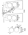
- the transfer belt 15 It can be arranged in an exchangeable cassette 28 (see FIG. 7), which is imaged by a pixel transfer unit 14 arranged far away from the printing form cylinder 1 and is then turned on the printing form cylinder 1, whereby the substance parts 27 adhering to their surface are transferred to the cassette by an image dispensing unit 23 which is integrated in the cassette or which can be adjusted thereon.
- the transfer belt 15 can also be designed with the pixel transfer unit 14 and the image transfer unit 23 in the form of a retrofitting robot 29 (see FIG. 8) which can be moved along the printing machine on a rail system 30 and with its end carrying the image delivery device 23 alternately to different ones Printing form cylinder 1 is adjustable.
- the transfer belt 15 is guided over a plurality of deflection rollers 31, which are mounted on individually pivotable levers, as a result of which the retooling robot 29 is highly mobile.
- the imaging of the transfer belt 15 can also be carried out by a pixel transfer unit 2 of the first exemplary embodiment, which works on the principle of an inkjet printer.
- a pixel transfer unit 2 of the first exemplary embodiment which works on the principle of an inkjet printer.
- the image delivery device 23 can be carried out.
- the substance parts deposited on the transfer belt 15 can be heated up Various types are carried out, such as a separate heating device 32 upstream of the roller 24 (see FIG. 2).
- the substance transfer can be magnetically or electrostatically supported if the substance is appropriately doped (see magnet 33 in FIG. 7 c).
- thermoplastic or a wax can be used as the substance for the imaging.
- the gravure printing plate produced by the method according to the invention and with a device according to the invention can be restored very quickly for a further imaging process after a printing process has ended.
- an extinguishing device 34 is placed on the printing form cylinder 1, which liquefies the thermoplastic substance by means of a heat source and removes it from the printing form cylinder 1 by means of a wiping and / or blowing or suction device.
- non-woven fabric tapes can also be used, which absorb the liquefied substance into the interstices of the fibers via capillary forces.
- the printing form cylinder 1 is preferably made of a ceramic material. Due to the high wear resistance and high heat resistance, such a printing form cylinder has a long service life even with frequently changing print images. At the same time, wear on a doctor blade sliding on ceramic webs is reduced.
Landscapes
- Engineering & Computer Science (AREA)
- Manufacturing & Machinery (AREA)
- Physics & Mathematics (AREA)
- Optics & Photonics (AREA)
- Thermal Sciences (AREA)
- Manufacture Or Reproduction Of Printing Formes (AREA)
- Printing Methods (AREA)
Applications Claiming Priority (2)
| Application Number | Priority Date | Filing Date | Title |
|---|---|---|---|
| DE3837941A DE3837941A1 (de) | 1988-11-09 | 1988-11-09 | Verfahren und vorrichtung zur herstellung einer tiefdruckform |
| DE3837941 | 1988-11-09 |
Publications (3)
| Publication Number | Publication Date |
|---|---|
| EP0368177A2 true EP0368177A2 (fr) | 1990-05-16 |
| EP0368177A3 EP0368177A3 (en) | 1990-12-05 |
| EP0368177B1 EP0368177B1 (fr) | 1993-07-14 |
Family
ID=6366770
Family Applications (1)
| Application Number | Title | Priority Date | Filing Date |
|---|---|---|---|
| EP89120427A Expired - Lifetime EP0368177B1 (fr) | 1988-11-09 | 1989-11-04 | Procédé et dispositif de fabrication de plaques d'impression en creux |
Country Status (3)
| Country | Link |
|---|---|
| EP (1) | EP0368177B1 (fr) |
| JP (1) | JP2801299B2 (fr) |
| DE (2) | DE3837941A1 (fr) |
Cited By (4)
| Publication number | Priority date | Publication date | Assignee | Title |
|---|---|---|---|---|
| EP0813957A2 (fr) † | 1996-06-19 | 1997-12-29 | MAN Roland Druckmaschinen AG | Procédé et appareil pour l'impression en creux utilisant une forme effaçable |
| WO2003041961A1 (fr) * | 2001-11-17 | 2003-05-22 | Erhard Lorch | Procede de realisation de moules de rotogravure, moules de rotogravure et leur utilisation |
| US6928930B1 (en) | 1995-05-04 | 2005-08-16 | Man Roland Druckmaschinen Ag | Device for cleaning printing cylinders |
| WO2012143517A1 (fr) * | 2011-04-21 | 2012-10-26 | Fercon GmbH | Dispositif et procédé permettant de produire des formes d'impression offset ou en creux ou d'imprimer des supports d'impression cylindriques |
Families Citing this family (8)
| Publication number | Priority date | Publication date | Assignee | Title |
|---|---|---|---|---|
| DE4428865A1 (de) * | 1994-08-05 | 1995-01-12 | Michael Schandelmaier | Druckformloses Druckverfahren |
| US6631676B2 (en) | 1995-02-07 | 2003-10-14 | Man Roland Druckmaschinen Ag | Process and apparatus for gravure |
| DE19503951C2 (de) * | 1995-02-07 | 1998-04-09 | Roland Man Druckmasch | Verfahren und Vorrichtung für den Tiefdruck |
| DE19645934A1 (de) * | 1996-11-07 | 1998-05-14 | Roland Man Druckmasch | Rasterwalze innerhalb eines Auftragswerkes einer Rotationsdruckmaschine |
| DE10049576B4 (de) * | 2000-10-06 | 2014-07-24 | Manroland Web Systems Gmbh | Einrichtung zur Herstellung von Druckformen |
| DE10208270A1 (de) | 2002-02-26 | 2003-09-04 | Roland Man Druckmasch | Lackiereinrichtung |
| US8157944B2 (en) * | 2007-11-26 | 2012-04-17 | Neenah Paper, Inc. | Methods of making stenciled screens |
| CN103991270A (zh) * | 2014-06-03 | 2014-08-20 | 中山火炬职业技术学院 | 一种基于喷墨保护实现重复利用的凹印版滚筒及印刷方法 |
Citations (2)
| Publication number | Priority date | Publication date | Assignee | Title |
|---|---|---|---|---|
| EP0264604A2 (fr) * | 1986-10-23 | 1988-04-27 | M.A.N.-ROLAND Druckmaschinen Aktiengesellschaft | Plaque d'impression lithographique |
| GB2198085A (en) * | 1986-11-29 | 1988-06-08 | Stc Plc | Printing apparatus and process |
Family Cites Families (1)
| Publication number | Priority date | Publication date | Assignee | Title |
|---|---|---|---|---|
| EP0101266A3 (fr) * | 1982-08-09 | 1985-04-03 | Milliken Research Corporation | Procédé et appareil pour l'impression |
-
1988
- 1988-11-09 DE DE3837941A patent/DE3837941A1/de active Granted
-
1989
- 1989-11-04 DE DE8989120427T patent/DE58904910D1/de not_active Expired - Lifetime
- 1989-11-04 EP EP89120427A patent/EP0368177B1/fr not_active Expired - Lifetime
- 1989-11-09 JP JP1290163A patent/JP2801299B2/ja not_active Expired - Lifetime
Patent Citations (2)
| Publication number | Priority date | Publication date | Assignee | Title |
|---|---|---|---|---|
| EP0264604A2 (fr) * | 1986-10-23 | 1988-04-27 | M.A.N.-ROLAND Druckmaschinen Aktiengesellschaft | Plaque d'impression lithographique |
| GB2198085A (en) * | 1986-11-29 | 1988-06-08 | Stc Plc | Printing apparatus and process |
Cited By (5)
| Publication number | Priority date | Publication date | Assignee | Title |
|---|---|---|---|---|
| US6928930B1 (en) | 1995-05-04 | 2005-08-16 | Man Roland Druckmaschinen Ag | Device for cleaning printing cylinders |
| EP0813957A2 (fr) † | 1996-06-19 | 1997-12-29 | MAN Roland Druckmaschinen AG | Procédé et appareil pour l'impression en creux utilisant une forme effaçable |
| EP0813957B2 (fr) † | 1996-06-19 | 2004-11-03 | MAN Roland Druckmaschinen AG | Procédé et appareil pour l'impression en creux utilisant une forme effaçable |
| WO2003041961A1 (fr) * | 2001-11-17 | 2003-05-22 | Erhard Lorch | Procede de realisation de moules de rotogravure, moules de rotogravure et leur utilisation |
| WO2012143517A1 (fr) * | 2011-04-21 | 2012-10-26 | Fercon GmbH | Dispositif et procédé permettant de produire des formes d'impression offset ou en creux ou d'imprimer des supports d'impression cylindriques |
Also Published As
| Publication number | Publication date |
|---|---|
| EP0368177B1 (fr) | 1993-07-14 |
| DE3837941C2 (fr) | 1990-08-30 |
| DE58904910D1 (de) | 1993-08-19 |
| DE3837941A1 (de) | 1990-05-10 |
| JPH02187335A (ja) | 1990-07-23 |
| JP2801299B2 (ja) | 1998-09-21 |
| EP0368177A3 (en) | 1990-12-05 |
Similar Documents
| Publication | Publication Date | Title |
|---|---|---|
| DE3882608T2 (de) | Lithografische Vorrichtung und Verfahren zur Tintenstrahl-Übertragung. | |
| EP0954443B1 (fr) | Dispositif et procede d'impression sur un materiau de support a l'aide d'une couche de glace structuree | |
| EP0368177B1 (fr) | Procédé et dispositif de fabrication de plaques d'impression en creux | |
| US5154121A (en) | System and method to apply a printing image on a printing machine cylinder having ink accepting receptors or cells, in accordance with electronically furnished image information | |
| EP1170122B1 (fr) | Appareil pour la formation d'image sur des surfaces dans des machines d'impression | |
| DE3820340C1 (en) | Pad printing machine | |
| DE2202545A1 (de) | Verfahren und vorrichtung zum bedrucken von gegenstaenden | |
| EP0339409B1 (fr) | Procédé et appareil pour l'impression flexographique | |
| EP0368179B1 (fr) | Procédé et appareil de fabrication intégrée de plaques d'impression sur machine offset | |
| WO2001002170A1 (fr) | Procede et dispositif d'impression pour imprimer un materiau support et pour nettoyer un cylindre d'impression | |
| EP0453855B1 (fr) | Préparation du dispositif d'encrage d'une machine à imprimer lors du changement de la commande d'impression | |
| EP0428894B1 (fr) | Procédé de préparation d'une unité d'impression et unité d'impression utilisable pour sa mise en oeuvre | |
| DE29507416U1 (de) | Einrichtung zum Reinigen von farbübertragenden Zylindern | |
| EP0368180B1 (fr) | Procédé de fabrication d'un cylindre d'impression portant une image | |
| WO1999042291A1 (fr) | Rotative a feuilles comportant des unites d'impression pour l'impression en polychromie et au moins une unite de couchage | |
| DE69400156T2 (de) | Druckverfahren und Presse für die Herstellung | |
| EP0368178B1 (fr) | Procédé de formation directe de l'image sur un cylindre d'impression | |
| DE3008981A1 (de) | Umstellbares heber-/filmfarbwerk | |
| DE19801623A1 (de) | Verfahren zum Betrieb einer Offset-Rotationsdruckmaschine | |
| DE19926185A1 (de) | Variodruckmaschine, insbesondere Tampondruckmaschine | |
| DE19715243B4 (de) | Druckmaschine mit Reinigungseinrichtungen zum Reinigen von Zylindern und Walzen | |
| DE10038166C2 (de) | Tampondruckmaschine | |
| EP0412179A1 (fr) | Dispositif d'encrage pour imprimante thermique par transfert | |
| DE10338974A1 (de) | Druckvorrichtung und Druckverfahren | |
| DE8817148U1 (de) | Rotationsdruckmaschine mit einer Vorrichtung zur Zuführung eines Druckbildträgers zum Druckformzylinder |
Legal Events
| Date | Code | Title | Description |
|---|---|---|---|
| PUAI | Public reference made under article 153(3) epc to a published international application that has entered the european phase |
Free format text: ORIGINAL CODE: 0009012 |
|
| AK | Designated contracting states |
Kind code of ref document: A2 Designated state(s): DE FR GB NL SE |
|
| PUAL | Search report despatched |
Free format text: ORIGINAL CODE: 0009013 |
|
| AK | Designated contracting states |
Kind code of ref document: A3 Designated state(s): DE FR GB NL SE |
|
| RHK1 | Main classification (correction) |
Ipc: B41C 1/055 |
|
| 17P | Request for examination filed |
Effective date: 19901030 |
|
| 17Q | First examination report despatched |
Effective date: 19920922 |
|
| GRAA | (expected) grant |
Free format text: ORIGINAL CODE: 0009210 |
|
| AK | Designated contracting states |
Kind code of ref document: B1 Designated state(s): DE FR GB NL SE |
|
| REF | Corresponds to: |
Ref document number: 58904910 Country of ref document: DE Date of ref document: 19930819 |
|
| ET | Fr: translation filed | ||
| GBT | Gb: translation of ep patent filed (gb section 77(6)(a)/1977) |
Effective date: 19931022 |
|
| PLBE | No opposition filed within time limit |
Free format text: ORIGINAL CODE: 0009261 |
|
| STAA | Information on the status of an ep patent application or granted ep patent |
Free format text: STATUS: NO OPPOSITION FILED WITHIN TIME LIMIT |
|
| 26N | No opposition filed | ||
| EAL | Se: european patent in force in sweden |
Ref document number: 89120427.3 |
|
| REG | Reference to a national code |
Ref country code: GB Ref legal event code: IF02 |
|
| PGFP | Annual fee paid to national office [announced via postgrant information from national office to epo] |
Ref country code: NL Payment date: 20031030 Year of fee payment: 15 |
|
| PGFP | Annual fee paid to national office [announced via postgrant information from national office to epo] |
Ref country code: SE Payment date: 20031103 Year of fee payment: 15 |
|
| PG25 | Lapsed in a contracting state [announced via postgrant information from national office to epo] |
Ref country code: SE Free format text: LAPSE BECAUSE OF NON-PAYMENT OF DUE FEES Effective date: 20041105 |
|
| PG25 | Lapsed in a contracting state [announced via postgrant information from national office to epo] |
Ref country code: NL Free format text: LAPSE BECAUSE OF NON-PAYMENT OF DUE FEES Effective date: 20050601 |
|
| EUG | Se: european patent has lapsed | ||
| NLV4 | Nl: lapsed or anulled due to non-payment of the annual fee |
Effective date: 20050601 |
|
| PGFP | Annual fee paid to national office [announced via postgrant information from national office to epo] |
Ref country code: DE Payment date: 20081121 Year of fee payment: 20 |
|
| REG | Reference to a national code |
Ref country code: FR Ref legal event code: CD |
|
| PGFP | Annual fee paid to national office [announced via postgrant information from national office to epo] |
Ref country code: FR Payment date: 20081113 Year of fee payment: 20 |
|
| PGFP | Annual fee paid to national office [announced via postgrant information from national office to epo] |
Ref country code: GB Payment date: 20081117 Year of fee payment: 20 |
|
| REG | Reference to a national code |
Ref country code: GB Ref legal event code: PE20 Expiry date: 20091103 |
|
| PG25 | Lapsed in a contracting state [announced via postgrant information from national office to epo] |
Ref country code: GB Free format text: LAPSE BECAUSE OF EXPIRATION OF PROTECTION Effective date: 20091103 |