EP0367196B1 - Unité de guidage et d'entraînement linéaire - Google Patents
Unité de guidage et d'entraînement linéaire Download PDFInfo
- Publication number
- EP0367196B1 EP0367196B1 EP89120125A EP89120125A EP0367196B1 EP 0367196 B1 EP0367196 B1 EP 0367196B1 EP 89120125 A EP89120125 A EP 89120125A EP 89120125 A EP89120125 A EP 89120125A EP 0367196 B1 EP0367196 B1 EP 0367196B1
- Authority
- EP
- European Patent Office
- Prior art keywords
- driving unit
- unit according
- rail track
- linear guiding
- ball
- Prior art date
- Legal status (The legal status is an assumption and is not a legal conclusion. Google has not performed a legal analysis and makes no representation as to the accuracy of the status listed.)
- Expired - Lifetime
Links
Images


Classifications
-
- F—MECHANICAL ENGINEERING; LIGHTING; HEATING; WEAPONS; BLASTING
- F16—ENGINEERING ELEMENTS AND UNITS; GENERAL MEASURES FOR PRODUCING AND MAINTAINING EFFECTIVE FUNCTIONING OF MACHINES OR INSTALLATIONS; THERMAL INSULATION IN GENERAL
- F16C—SHAFTS; FLEXIBLE SHAFTS; ELEMENTS OR CRANKSHAFT MECHANISMS; ROTARY BODIES OTHER THAN GEARING ELEMENTS; BEARINGS
- F16C29/00—Bearings for parts moving only linearly
- F16C29/04—Ball or roller bearings
- F16C29/06—Ball or roller bearings in which the rolling bodies circulate partly without carrying load
- F16C29/0633—Ball or roller bearings in which the rolling bodies circulate partly without carrying load with a bearing body defining a U-shaped carriage, i.e. surrounding a guide rail or track on three sides
- F16C29/0635—Ball or roller bearings in which the rolling bodies circulate partly without carrying load with a bearing body defining a U-shaped carriage, i.e. surrounding a guide rail or track on three sides whereby the return paths are provided as bores in a main body of the U-shaped carriage, e.g. the main body of the U-shaped carriage is a single part with end caps provided at each end
- F16C29/0638—Ball or roller bearings in which the rolling bodies circulate partly without carrying load with a bearing body defining a U-shaped carriage, i.e. surrounding a guide rail or track on three sides whereby the return paths are provided as bores in a main body of the U-shaped carriage, e.g. the main body of the U-shaped carriage is a single part with end caps provided at each end with balls
- F16C29/0642—Ball or roller bearings in which the rolling bodies circulate partly without carrying load with a bearing body defining a U-shaped carriage, i.e. surrounding a guide rail or track on three sides whereby the return paths are provided as bores in a main body of the U-shaped carriage, e.g. the main body of the U-shaped carriage is a single part with end caps provided at each end with balls with four rows of balls
- F16C29/0645—Ball or roller bearings in which the rolling bodies circulate partly without carrying load with a bearing body defining a U-shaped carriage, i.e. surrounding a guide rail or track on three sides whereby the return paths are provided as bores in a main body of the U-shaped carriage, e.g. the main body of the U-shaped carriage is a single part with end caps provided at each end with balls with four rows of balls with load directions in O-arrangement
-
- B—PERFORMING OPERATIONS; TRANSPORTING
- B23—MACHINE TOOLS; METAL-WORKING NOT OTHERWISE PROVIDED FOR
- B23Q—DETAILS, COMPONENTS, OR ACCESSORIES FOR MACHINE TOOLS, e.g. ARRANGEMENTS FOR COPYING OR CONTROLLING; MACHINE TOOLS IN GENERAL CHARACTERISED BY THE CONSTRUCTION OF PARTICULAR DETAILS OR COMPONENTS; COMBINATIONS OR ASSOCIATIONS OF METAL-WORKING MACHINES, NOT DIRECTED TO A PARTICULAR RESULT
- B23Q1/00—Members which are comprised in the general build-up of a form of machine, particularly relatively large fixed members
- B23Q1/25—Movable or adjustable work or tool supports
- B23Q1/26—Movable or adjustable work or tool supports characterised by constructional features relating to the co-operation of relatively movable members; Means for preventing relative movement of such members
- B23Q1/267—Movable or adjustable work or tool supports characterised by constructional features relating to the co-operation of relatively movable members; Means for preventing relative movement of such members with means to prevent skewness between the relatively slidable members
-
- B—PERFORMING OPERATIONS; TRANSPORTING
- B23—MACHINE TOOLS; METAL-WORKING NOT OTHERWISE PROVIDED FOR
- B23Q—DETAILS, COMPONENTS, OR ACCESSORIES FOR MACHINE TOOLS, e.g. ARRANGEMENTS FOR COPYING OR CONTROLLING; MACHINE TOOLS IN GENERAL CHARACTERISED BY THE CONSTRUCTION OF PARTICULAR DETAILS OR COMPONENTS; COMBINATIONS OR ASSOCIATIONS OF METAL-WORKING MACHINES, NOT DIRECTED TO A PARTICULAR RESULT
- B23Q1/00—Members which are comprised in the general build-up of a form of machine, particularly relatively large fixed members
- B23Q1/25—Movable or adjustable work or tool supports
- B23Q1/26—Movable or adjustable work or tool supports characterised by constructional features relating to the co-operation of relatively movable members; Means for preventing relative movement of such members
- B23Q1/40—Movable or adjustable work or tool supports characterised by constructional features relating to the co-operation of relatively movable members; Means for preventing relative movement of such members using ball, roller or wheel arrangements
-
- B—PERFORMING OPERATIONS; TRANSPORTING
- B23—MACHINE TOOLS; METAL-WORKING NOT OTHERWISE PROVIDED FOR
- B23Q—DETAILS, COMPONENTS, OR ACCESSORIES FOR MACHINE TOOLS, e.g. ARRANGEMENTS FOR COPYING OR CONTROLLING; MACHINE TOOLS IN GENERAL CHARACTERISED BY THE CONSTRUCTION OF PARTICULAR DETAILS OR COMPONENTS; COMBINATIONS OR ASSOCIATIONS OF METAL-WORKING MACHINES, NOT DIRECTED TO A PARTICULAR RESULT
- B23Q1/00—Members which are comprised in the general build-up of a form of machine, particularly relatively large fixed members
- B23Q1/25—Movable or adjustable work or tool supports
- B23Q1/44—Movable or adjustable work or tool supports using particular mechanisms
- B23Q1/56—Movable or adjustable work or tool supports using particular mechanisms with sliding pairs only, the sliding pairs being the first two elements of the mechanism
- B23Q1/58—Movable or adjustable work or tool supports using particular mechanisms with sliding pairs only, the sliding pairs being the first two elements of the mechanism a single sliding pair
-
- F—MECHANICAL ENGINEERING; LIGHTING; HEATING; WEAPONS; BLASTING
- F16—ENGINEERING ELEMENTS AND UNITS; GENERAL MEASURES FOR PRODUCING AND MAINTAINING EFFECTIVE FUNCTIONING OF MACHINES OR INSTALLATIONS; THERMAL INSULATION IN GENERAL
- F16C—SHAFTS; FLEXIBLE SHAFTS; ELEMENTS OR CRANKSHAFT MECHANISMS; ROTARY BODIES OTHER THAN GEARING ELEMENTS; BEARINGS
- F16C29/00—Bearings for parts moving only linearly
- F16C29/04—Ball or roller bearings
- F16C29/06—Ball or roller bearings in which the rolling bodies circulate partly without carrying load
- F16C29/0602—Details of the bearing body or carriage or parts thereof, e.g. methods for manufacturing or assembly
- F16C29/0604—Details of the bearing body or carriage or parts thereof, e.g. methods for manufacturing or assembly of the load bearing section
-
- F—MECHANICAL ENGINEERING; LIGHTING; HEATING; WEAPONS; BLASTING
- F16—ENGINEERING ELEMENTS AND UNITS; GENERAL MEASURES FOR PRODUCING AND MAINTAINING EFFECTIVE FUNCTIONING OF MACHINES OR INSTALLATIONS; THERMAL INSULATION IN GENERAL
- F16C—SHAFTS; FLEXIBLE SHAFTS; ELEMENTS OR CRANKSHAFT MECHANISMS; ROTARY BODIES OTHER THAN GEARING ELEMENTS; BEARINGS
- F16C33/00—Parts of bearings; Special methods for making bearings or parts thereof
- F16C33/30—Parts of ball or roller bearings
- F16C33/58—Raceways; Race rings
- F16C33/60—Raceways; Race rings divided or split, e.g. comprising two juxtaposed rings
- F16C33/61—Raceways; Race rings divided or split, e.g. comprising two juxtaposed rings formed by wires
-
- F—MECHANICAL ENGINEERING; LIGHTING; HEATING; WEAPONS; BLASTING
- F16—ENGINEERING ELEMENTS AND UNITS; GENERAL MEASURES FOR PRODUCING AND MAINTAINING EFFECTIVE FUNCTIONING OF MACHINES OR INSTALLATIONS; THERMAL INSULATION IN GENERAL
- F16C—SHAFTS; FLEXIBLE SHAFTS; ELEMENTS OR CRANKSHAFT MECHANISMS; ROTARY BODIES OTHER THAN GEARING ELEMENTS; BEARINGS
- F16C2322/00—Apparatus used in shaping articles
- F16C2322/39—General build up of machine tools, e.g. spindles, slides, actuators
-
- Y—GENERAL TAGGING OF NEW TECHNOLOGICAL DEVELOPMENTS; GENERAL TAGGING OF CROSS-SECTIONAL TECHNOLOGIES SPANNING OVER SEVERAL SECTIONS OF THE IPC; TECHNICAL SUBJECTS COVERED BY FORMER USPC CROSS-REFERENCE ART COLLECTIONS [XRACs] AND DIGESTS
- Y10—TECHNICAL SUBJECTS COVERED BY FORMER USPC
- Y10T—TECHNICAL SUBJECTS COVERED BY FORMER US CLASSIFICATION
- Y10T74/00—Machine element or mechanism
- Y10T74/18—Mechanical movements
- Y10T74/18568—Reciprocating or oscillating to or from alternating rotary
- Y10T74/18576—Reciprocating or oscillating to or from alternating rotary including screw and nut
- Y10T74/18648—Carriage surrounding, guided by, and primarily supported by member other than screw [e.g., linear guide, etc.]
Definitions
- the invention relates to a linear guide and drive unit, comprising a rail guide with at least one rail track and a guide slide guided on the rail guide and driven by a linear drive, the guide slide being produced in one piece with a drive element housing of the linear drive and with mounting means for rolling guide means, and wherein the rolling guide means are from load-bearing rows of ball bearings are formed, at least two ball revolutions, which rows of ball balls are in engagement with a ball track on the rail guide side and a ball track on the slide side.
- a generic linear guide and drive unit is known from EP-A-0 238 708.
- the slide-side ball roller tracks are molded directly into the material of the guide slide.
- a non-generic linear guide and drive unit is from a brochure "Star rail guide tables" with the printed matter no. 120-0 / 1/88 / 6Bi known.
- a guide carriage is guided on two mutually parallel rail tracks, which are laid on a common base plate.
- several U-shaped guide bodies are fastened to it by screwing, in which the ball revolutions are accommodated are.
- a drive element housing protruding between the rail strands is formed on the guide carriage, in which a ball nut is installed.
- the ball nut is in engagement with a threaded spindle which extends from one end of the base plate to the other between the two rail tracks.
- the threaded spindle is rotatably mounted on crossbars at the ends of the base plate and can be connected to a rotary drive.
- a disadvantage of this known embodiment is that the guide bodies for the ball revolutions are formed by separate parts which have to be fastened to the slide by screws.
- the invention is based on the object of producing a linear guide and drive unit which has a high wear resistance regardless of the material of the guide carriage.
- At least one recess for receiving a one-piece multi-steel insert is formed in the mounting means, which multi-steel insert has the slide-side ball raceways of two ball revolutions.
- the linear guide and drive unit according to the invention is compact and can be manufactured simply and economically, since the slide is made in one piece with the holding means and the drive element housing and therefore subsequent adjustment and fastening of the holding means is not necessary.
- the guide slide can be formed together with the drive element housing and the holding means by an extruded profile, so that the production is further simplified.
- the recesses in the mounting means and in the drive element housing can already be largely made in the course of extrusion, so that machining is only necessary to a small extent.
- the guide slide can be made of aluminum, for example, if the loads to be expected allow it, without premature wear and tear being expected.
- the drive device can be varied within wide limits, in particular belt drives, spindle drives and pneumatic or hydraulic cylinder piston units can be used for the drive.
- the drive can be a screw drive, in which the drive element housing receives a nut of the screw drive and the associated threaded spindle is rotatably mounted in axles parallel to the rail track in trusses which are connected to the rail track in the region of the ends of the rail track.
- Preferred drives are ball screws in which the ball nut is in thread-like engagement with the threaded spindle via balls guided in a closed path within the ball nut.
- Another also advantageous type of drive is based on the fact that the drive element housing is connected to a run of a belt drive which extends parallel to the longitudinal axis of the rail track between two cross members which are arranged in the end regions of the rail track.
- the two strands of the belt drive can be guided through a passage of the drive element housing, one strand of the belt drive being fixedly connected to the drive element housing within the passage, while the other strand runs freely through the passage.
- the linear guide and drive unit is preferably designed in such a way that the holder means, as is known in principle from the above-mentioned brochure "Star rail guide tables", enclose a rail track in a U-shape and that between legs of the holder means which are assigned to one another in the manner of U-legs and the side surfaces of the rail track adjacent to these legs are each arranged with two rows of support balls each with two ball revolutions.
- the position of the drive device relative to the rail track can also be varied within wide limits.
- An embodiment can be selected in which the drive element housing is arranged laterally next to one leg of the holding means. Such an embodiment is of particular interest when a low overall height of the linear guide and drive unit is required over a support surface supporting the rail track. A further reduction in the overall height is possible in that the drive device is accommodated in the height region of the guide carriage.
- the guide carriage can carry a wide variety of functional devices, for example functional devices of a machine tool. For this reason, it is proposed that the guide slide be designed with a clamping surface and clamping means for the construction of an attachment part.
- the multiple steel inserts in the holding means can be mounted such that they can swing about an axis perpendicular to the longitudinal axis of the rail track, this swing axis lying in the region of the longitudinal center of the respective supporting ball rows.
- the rows of supporting balls belonging to a common multiple steel insert can be secured in the associated ball roller tracks of the common multiple steel insert by a common retaining web unit.
- This retaining web unit can take over the securing of the multiple steel insert in the holding means simultaneously with the securing of the balls on the multiple steel insert.
- the retaining web unit can be part of at least one end plate fastened to the holding means, in which deflection guides are formed for the respective ball circulations.
- the retaining web units are each designed such that they allow the steel inserts to rock about an axis perpendicular to the rail line axis and / or about an axis parallel to the rail line axis.
- the steel inserts are held by the holding bridge units with a certain amount of play in the case of hard-elastic retaining bridge material.
- the rockability could also be made possible by the elastic deformability of the retaining web material.
- the multiple steel insert may also be advantageous to mount the multiple steel insert such that it can rock about an axis parallel to the longitudinal axis of the rail track.
- the recess intended to receive the multiple steel insert can be wedge-shaped in a cross section orthogonal to the axis of a rail track and the multiple steel insert can be correspondingly wedge-shaped.
- the linear guide and drive unit can be designed in such a way that on two side surfaces of the rail track located on both sides of a longitudinal symmetry plane of a rail track, two ball track tracks on the rail track side are arranged in a symmetrical arrangement on both sides of the plane of symmetry, and accordingly recesses for a multiple steel insert on both sides of the plane of symmetry in the holding means are provided.
- the ball track tracks on the rail track side are formed by the flanks of a longitudinal groove in a side surface of the rail track.
- the rail guide comprises a single rail track with a longitudinal axis and a longitudinal plane of symmetry containing this longitudinal axis, that a guide carriage is arranged symmetrically to the longitudinal plane of symmetry on the rail line and is guided by roller guide means symmetrical to the longitudinal symmetry plane that at the ends of the rail line Trusses are arranged and that a single drive device extending between the trusses is provided with a drive element which is movable parallel to the direction of the longitudinal axis and which is in driving connection outside the longitudinal axis with the guide carriage, the rail track on both sides of the longitudinal plane of symmetry with two each in a direction perpendicular to the Longitudinal axis and ball roller tracks spaced parallel to the longitudinal plane of symmetry for one row of supporting balls each of two balls arranged on both sides of the longitudinal plane of symmetry Is executed circumferences of the guide carriage and wherein the rows of support balls on one side of the plane of symmetry assigned to the longitudinal plane of symmetry
- Such a ball guide of the guide carriage on the rail track is known from DE-A-35 27 886.
- the guide carriage viewed in a cross section perpendicular to the longitudinal axis, can be designed in a substantially U-shaped assignment with a web part and two leg parts, two ball revolutions being arranged on the leg parts are.
- the position of the drive device relative to the rail track can be varied within wide limits.
- An embodiment is often selected in which the drive device is arranged at a distance from the longitudinal plane of symmetry to the side of one leg part of the guide carriage.
- the drive device prefferably be arranged in the region of the longitudinal plane of symmetry above the web part of the guide carriage.
- This design can be carried out so that a rotatable threaded spindle extends between the two cross members and that a socket for a ball nut is attached to the web part of the guide carriage, which is in thread-like engagement with the threaded spindle via balls guided in a closed path within the ball nut stands.
- the ball nut can be embedded in a depression in an end face of the socket which is normal to the longitudinal axis.
- a loop of flexible drive means in the form of a chain of a toothed belt or the like extends between the two cross members and that a strand of this loop is connected to the web part of the guide carriage.
- the connection of the loop to the guide carriage can be made in such a way that a guide and fastening block for the loop is arranged on the web part of the guide carriage, which has a clamping surface for fixing the one loop center on the web part and a tunnel for the passage of the other loop centers.
- the returning run of the loop can also be returned below the rail track, for example in a bottom recess of a base plate carrying the rail track.
- the object to be driven comes as close as possible to the longitudinal axis of the rail track; at the same time, the entire height of the rail track and, if necessary, the base plate can be used to accommodate the deflection rollers of the loop.
- a particularly compact embodiment with extensive encapsulation of the loop is obtained in this way.
- the linear guide and drive unit often drives a part that belongs, for example, to a machine tool or a handling machine.
- fastening means for connection to a part to be driven are attached to the frame or on the guide and fastening block.
- the fastening means can have mating surfaces for the positive, adjusting contact of the part to be driven.
- the rail track have a support surface for support on a support and mounting holes running perpendicular to this support surface for receiving the rail track on the Has carrier-holding fastening bolt.
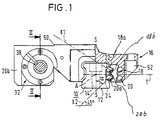
- a rail track is designated 10.
- This rail track is formed by a single, one-piece profile rail, which has a support surface 12 for resting on a support surface and can be fastened to this support surface by means of bolts which pass through bores 14 in the rail track 10.
- a guide carriage 16 is guided on the rail track 10.
- Two ball revolutions 18 and 20 are accommodated in the guide carriage 16 on both sides of a longitudinal plane of symmetry SS.
- the load-bearing rows of balls 18a and 20a of these ball revolutions 18, 20 each rest on a ball raceway 22 and 24 of the rail track 10 and also on ball raceways 18b and 20b of the guide carriage 16, only shown schematically in FIG. 1. That for them Arrangement of the ball revolutions 18 and 20 what has been said also applies to further ball revolutions which are accommodated on the other side, namely symmetrically to the arrangement shown.
- the axis of the rail track 10 is designated A.
- a plane orthogonal to the longitudinal symmetry plane S-S passes through the axis A.
- the force transmission planes of the load-bearing rows of balls 18a and 20a are designated K1 and K2. These power transmission planes enclose an angle ⁇ with the longitudinal plane of symmetry, which in the example is approximately 45 ° and can vary between approximately 30 ° and approximately 60 °.
- DE-A-35 27 886 For more details of the ball revolutions 18 and 20, reference is made to DE-A-35 27 886.
- a part to be driven can be attached to the guide carriage. This is placed on the carriage 16 and adjusted by adjusting edges 50. Bolts are used for fastening, which pass through bores 52 in the guide carriage 16.
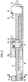
- FIG. 2 shows a cover bellows 56 which extends between the two cross members 34, 36 and the guide slide 16, so that contamination of the threaded spindle 38 and the rail track 10 is avoided.
- the crossbars 34, 36 are fastened to the rail track 10 by means of bolts which are screwed into bores 58 of the crossbars and penetrate the associated bores in the rail track 10.
- FIG. 4 analog parts are provided with the same reference numerals as in FIGS. 1 to 3, each increased by the number 100.
- the threaded spindle 138 lies here over the guide carriage 116 in the longitudinal plane of symmetry.
- a socket 160 for the ball nut 140 is attached to the guide carriage 116.
- threaded bores 164 are provided, through which a part to be carried can be fastened.
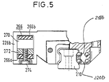
- a belt drive which is designated by 266, is provided as the drive device.
- the belt drive 266, for example a toothed belt drive, is formed by a belt loop.
- the belt loop runs over a pulley, which are attached to the two cross members, not shown here.
- One of the pulleys is provided with a drive, at least one of the pulleys is adjustable in the longitudinal direction of the rail track 210 in order to tension the belt.
- the cross members are attached to the rail track in exactly the same way as shown in FIGS. 2 and 3.
- the two longitudinal sections of the belt loop run through a tunnel 270 of part 226b.
- One longitudinal section 266a of the belt loop is clamped to the part 226b by a clamping plate 272 and a clamping bolt 274, while the other longitudinal section 266b runs freely through the tunnel 270.
- a guide and fastening block 376 is attached to the guide carriage 316.
- pulleys 378 are supported by bearings 380.
- a stepper motor is assigned to one of these pulleys.
- the belt pulley 378 can be adjusted in the longitudinal direction of the rail track 310 by means of a tensioning screw 382.
- a toothed belt 366 runs over the pulleys 378 and lies in the longitudinal plane of symmetry of the rail track 310. The ends of the lower longitudinal section 366a of the toothed belt 366 are anchored to the guide and fastening block 376.
- the upper longitudinal section 366b of the toothed belt loop 366 passes through a tunnel 386 of the guide and fastening block 376.
- Threaded bores 364 are provided in the guide and fastening block, so that a part to be carried can be fastened to the guide and fastening block.
- a pneumatic unit it can be attached both in the installation situation according to FIGS. 1 and 2 and in the installation situation according to FIG. 4.
- the pneumatic unit itself can be formed in a conventional manner from a cylinder-piston unit, with a piston rod engaging with its outer end on the guide carriage and the cylinder with its base on one of the cross members or vice versa.
- a pressure medium can act on the piston on both sides.
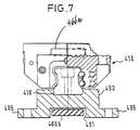
- FIG. 7 shows a modification of FIG. 6 in cross section: the loop is anchored to the guide carriage 416 with the two ends of its driving, upper run 466a.
- the returning, lower run 466b of the loop runs in a tunnel 491 of a carrier plate 493 on which the rail track 410 is fastened.
- the base plate 493 is provided with foot webs 495 which can be fastened to a carrier by means of bolts.
- FIG. 8 shows a linear guide and drive unit according to the invention which is similar to the embodiment according to FIG. 1.
- a guide carriage is generally designated 511 here.
- This guide carriage comprises a drive element housing 513 and holding means in the form of a guide body 515.
- the guide body 515 is U-shaped and is guided on a rail track 510.
- two ball revolutions 518 and 520 are accommodated, only the ball revolutions of the right U-leg 517 being shown.
- Each of these ball revolutions 518 and 520 has a row of supporting balls 518a and 520a.
- the rows of support balls 518a, 520a are guided in a track-side ball track 522 and 524.
- the slide-side ball roller tracks 518b, 520b are formed in a steel insert 521, which is mounted in the guide body 515, namely in its U-leg 517, rocking about a swing axis P.
- the steel insert 521 is made of steel, in particular hardened steel.
- the support ball rows 518a and 520a are secured in the slide-side ball roller tracks 518b and 520b by a web unit 523.
- the web unit is formed by two half-webs which meet in the longitudinal center of the guide body 515 and are centered there against one another. These half webs start from end plates which are attached to the end faces of the guide body 515 perpendicular to the rail axis. One of these end plates is shown in the left half of FIG.
- end plates are attached to the guide body 515 by screws 525.
- the half webs are each integrally connected to the end plates 529.
- DE-A-35 27 886 In addition to securing the rows of supporting balls 518a and 520a in the ball raceways 518b and 520b, the web unit 523 also serves to secure the steel inserts 521 in a recess 527 of the guide body 515. Longitudinal sealing strips 531, 533 and end sealing elements 535 serve to seal the ball circulations 518 and 520.
- return channels 518d, 520d are drilled in the guide body 515.
- deflection guides are formed between the rows of supporting balls 518a, 520a and the rows of return balls 518c and 520c.
- the threaded spindle 538 and the ball nut 540 are in engagement with one another by an endless row of balls, as is known from German patents 28 05 141, 28 34 299 and 29 14 756.
- the carriage 511 is extruded in one piece from aluminum with the drive element housing 513 and the guide body 515.
- the essential cavities in the drive element housing 513 and in the guide body 515 have already arisen during the extrusion process and essentially only those surfaces have been created by machining post-processing which do not run in a straight line over the entire length of the guide body 515.
- the guide carriage 511 has a clamping surface 539 on which an attachment part can be fastened, for example by means of screw bolts which are screwed into threaded bores 541 of the guide carriage 511.
- linear guide and drive unit could also be designed symmetrically with respect to the axis SS by providing a guide body 515 on each side of the threaded spindle 538.
- the carriage is generally designated 611. It comprises a guide body 615 and a drive element housing 613.
- the statements made with regard to FIG. 8 apply to the formation of the guide body 615 and the ball guides.
- the drive element housing 613 is designed here with a passage 670, through which the two strands 666a and 666b of a belt drive 666 pass.
- the belt run 666a is clamped to the drive element housing 613, while the belt run 666b runs freely through the passage 670.
- the belt drive 666 extends along the rail track 610 and is guided at the ends of the rail track 610 via rollers, one of which is provided with a drive.
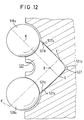
- FIGS. 10 and 11 show a shape of the steel insert 521 in which the back 521a is rounded in such a way that the steel insert can swing about the swing axis P.
- the contact surfaces 521b and 521c are also convex in such a way that the steel insert 521 can rock about the axis Q parallel to the longitudinal direction of the rail.
- the two swing options about the swing axis P according to FIG. 8 and about the swing axis Q according to FIG. 12 can be combined with one another.
- the contact lines L and L 'of the contact surfaces 521b and 521c degenerate at contact surfaces 527b and 527c.
- the rocking ability around the rail parallel axis Q ensures in any case that the force transmission planes K and K 'of the rows of balls 518a and 520a pass through the contact lines or contact points L and L'.
- the linear guide and drive unit according to the invention takes up little space with a simple construction.
- the guide sled is heavy-duty; it is non-rotatable, precise and easy to move on the rail track. A high positioning accuracy is guaranteed even at high driving speeds.
- the structure is made up of a few, economically producible parts.
Claims (34)
- Unité de guidage et d'entraînement linéaire comprenant un système de guidage sur rails pourvu d'au moins une voie (510) et un chariot de guidage (511) guidé sur le système de guidage sur rails et entraîné par un entraînement linéaire, le chariot de guidage (511) étant réalisé pour ne former qu'une seule pièce avec un boîtier d'éléments d'entraînement (513) de l'entraînement linéaire et avec des moyens de maintien (515) destinés à des moyens de guidage roulants (518, 520) et les moyens de guidage roulants (518, 520) étant constitués de séries de billes porteuses (518a, 520a) transmettant la charge d'au moins deux circuits de billes (518, 520), les séries de billes porteuses (518a, 520a) coopérant, chacune, avec une surface de roulement des billes (522, 524) située du côté du système de guidage sur rails et avec une surface de roulement des billes (518b, 520b) située du côté du chariot,
caractérisée en ce qu'est ménagé, dans les moyens de maintien (515), au moins un évidement (527) destiné à loger un insert en acier multiple (521) monobloc, insert en acier multiple (521) qui comporte les surfaces de roulement des billes (518b, 520b), situées du côté du chariot, de deux circuits de billes (518, 520). - Unité de guidage et d'entraînement linéaire selon la revendication 1, caractérisée en ce que le chariot de guidage (511), avec le boîtier d'éléments d'entraînement (513) et les moyens de maintien (515), est formé par un profilé extrudé.
- Unité de guidage et d'entraînement linéaire selon la revendication 2, caractérisée en ce que le profilé extrudé est constitué en aluminium.
- Unité de guidage et d'entraînement linéaire selon l'une des revendications 1 à 3, caractérisée en ce que le boîtier d'éléments d'entraînement (513) loge un écrou (540) d'un entraînement par vis (538, 540) et en ce que la tige filetée (538) associée est montée, selon un axe parallèle à la voie (510), de façon tournante dans des traverses, qui sont reliées dans la zone des extrémités de la voie (510) avec celle-ci.
- Unité de guidage et d'entraînement linéaire selon la revendication 4, caractérisée en ce que l'entraînement par vis (538, 540) est un entraînement par vis à billes, l'écrou sphérique (540) se trouvant en liaison du type fileté avec la tige filetée (538), par l'intermédiaire de billes guidées selon un circuit fermé à l'intérieur de l'écrou sphérique.
- Unité de guidage et d'entraînement linéaire selon l'une des revendications 1 à 3, caractérisée en ce que le boîtier d'éléments d'entraînement (613) est relié à un brin (666a) d'un entraînement à courroie (666), qui s'étend, parallèlement à l'axe longitudinal de la voie (610), entre deux traverses qui sont situées dans les zones terminales de la voie (610).
- Unité de guidage et d'entraînement linéaire selon la revendication 6, caractérisée en ce que les deux brins (666a, 666b) de l'entraînement à courroie (666) passent à travers un passage (670) du boîtier d'éléments d'entraînement (613), l'un (666a) des brins de l'entraînement à courroie étant relié fixement avec le boîtier d'éléments d'entraînement (613), à l'intérieur du passage (670), tandis que l'autre brin (666b) passe librement à travers le passage (670).
- Unité de guidage et d'entraînement linéaire selon l'une des revendications 1 à 7, caractérisée en ce que les moyens de maintien (515) entourent la voie (510) selon une forme de U et en ce qu'entre des branches (517, 519), associées l'une à l'autre de façon similaire à des branches de U, des moyens de maintien (515) et les surfaces latérales, adjacentes à ces branches, de la voie (510), sont disposées respectivement deux séries de billes porteuses (518a, 520a) appartenant respectivement à deux circuits de billes (518, 520).
- Unité de guidage et d'entraînement linéaire selon la revendication 8, caractérisée en ce que le boîtier d'éléments d'entraînement (513) est disposé latéralement à côté d'une branche (517) des moyens de maintien (515).
- Unité de guidage et d'entraînement linéaire selon la revendication 8, caractérisée en ce que le boîtier d'éléments d'entraînement est disposé sur une zone formant âme des moyens de maintien.
- Unité de guidage et d'entraînement linéaire selon l'une des revendications 1 à 10, caractérisée en ce que le chariot de guidage (511) présente une surface de bridage (539) et des moyens de fixation (541) pour le montage d'une pièce rapportée.
- Unité de guidage et d'entraînement linéaire selon l'une des revendications 1 à 11, caractérisée en ce que les inserts en acier multiples (521) sont montés dans les moyens de maintien (515) de façon à pouvoir basculer autour d'un axe (P) perpendiculaire à l'axe longitudinal de la voie, cet axe de basculement (P) étant situé dans la zone du milieu de la longueur des séries de billes porteuses (518a, 520a) associées.
- Unité de guidage et d'entraînement linéaire selon l'une des revendications 1 à 12, caractérisée en ce que les séries de billes porteuses (518a, 520a) associées à un insert en acier multiple (521) commun sont maintenues dans les surfaces de roulement des billes (518b, 520b) associées de l'insert en acier multiple (521) commun par une unité formant barrette de maintien (523) commune.
- Unité de guidage et d'entraînement linéaire selon la revendication 13, caractérisée en ce que l'unité formant barrette de maintien (523) fait partie d'au moins une plaque terminale (529), fixée sur les moyens de maintien, dans laquelle sont prévus des guidages de renvoi destinés à chaque circuit de billes (518, 520).
- Unité de guidage et d'entraînement linéaire selon l'une des revendications 1 à 14, caractérisée en ce que l'insert en acier multiple (521) est monté de façon à pouvoir basculer autour d'un axe parallèle à l'axe longitudinal de la voie.
- Unité de guidage et d'entraînement linéaire selon l'une des revendications 1 à 15, caractérisée en ce que l'évidement (527), vu en section transversale orthogonale par rapport à l'axe d'une voie (510), présente une forme de coin et en ce que l'insert en acier multiple (521) présente, de façon correspondante, une forme de coin.
- Unité de guidage et d'entraînement linéaire selon l'une des revendications 1 à 16, caractérisée en ce que, sur deux surfaces latérales de la voie (510) situées de part et d'autre d'un plan de symétrie longitudinal d'une voie (510), sont placées respectivement deux surfaces de roulement des billes (522, 524) situées du côté de la voie, disposées de façon symétrique de part et d'autre du plan de symétrie, et en ce que sont prévus, de façon correspondante, des évidements (527) ménagés dans les moyens de maintien (515), destinés chacun à un insert en acier multiple (521) de part et d'autre du plan de symétrie.
- Unité de guidage et d'entraînement linéaire selon l'une des revendications 1 à 17, caractérisée en ce que les surfaces de roulement des billes (522, 524) situées du côté de la voie sont formées par les flancs d'une rainure longitudinale ménagée dans une surface latérale de la voie (510).
- Unité de guidage et d'entraînement linéaire selon l'une des revendications 1 à 18, caractérisée en ce que le système de guidage sur rails comprend une seule voie (10) avec un axe longitudinal (A) et un plan de symétrie longitudinale (S-S) contenant cet axe longitudinal (A), en ce que, sur la voie (10), un chariot de guidage (16) est disposé de façon symétrique par rapport au plan de symétrie longitudinale (S-S) et est guidé par des moyens de guidage roulants (18, 20) symétriques par rapport au plan de symétrie longitudinale (S-S), en ce que des traverses (34, 36) sont disposées aux extrémités de la voie (10), et en ce qu'est prévu un seul dispositif d'entraînement (38, 40) s'étendant entre les traverses (34, 36), avec un élément d'entraînement (40) mobile parallèlement à la direction de l'axe longitudinal (A), qui se trouve, en-dehors de l'axe longitudinal (A), en liaison d'entraînement avec le chariot de guidage,
la voie (10), de part et d'autre du plan de symétrie longitudinale (S-S), étant réalisée avec respectivement deux surfaces de roulement des billes (22, 24) espacées dans une direction perpendiculaire à l'axe longitudinal (A) et parallèle au plan de symétrie longitudinale (S-S), destinées chacune à une série de billes porteuses (18a, 20a) appartenant respectivement à deux circuits de billes (18, 20), disposés de part et d'autre du plan de symétrie longitudinal (S-S), du chariot de guidage (16), et les plans de transmission des forces (K1, K2) associés aux séries de billes porteuses (18a, 20a) d'un côté du plan de symétrie (S-S) formant chacun, avec le plan de symétrie longitudinale (S-S), un angle α de 30° à 60°, de préférence d'environ 45°, divergent par rapport du plan de symétrie longitudinale (S-S). - Unité de guidage et d'entraînement linéaire selon la revendication 19, caractérisée en ce que le chariot de guidage (16), vu en section transversale perpendiculaire à l'axe longitudinal (A), est réalisé, selon une configuration sensiblement en forme de U, avec une partie formant âme (16c) et deux parties formant branches (16a, 16b), deux circuits de billes (18, 20) étant disposés respectivement sur les parties formant branches (16a, 16b).
- Unité de guidage et d'entraînement linéaire selon la revendication 20, caractérisée en ce que le dispositif d'entraînement (38, 40) est placé à distance du plan de symétrie longitudinale (S-S), sur le côté d'une partie formant branche (16b) du chariot de guidage (16a).
- Unité de guidage et d'entraînement linéaire selon la revendication 21, caractérisée en ce qu'un entraînement pneumatique s'étend entre les deux traverses.
- Unité de guidage et d'entraînement linéaire selon la revendication 20, caractérisée en ce que le dispositif d'entraînement (138, 140) est disposé, dans la zone du plan de symétrie longitudinale, au-dessus de la partie formant âme (116c) du chariot de guidage (116).
- Unité de guidage et d'entraînement linéaire selon la revendication 23, caractérisée en ce que s'étend, entre les deux traverses (134, 136), une tige filetée (138) rotative et en ce qu'est disposée, sur la partie formant âme (116c) du chariot de guidage (116), une monture (160) destinée à un écrou sphérique (140), qui se trouve en liaison du type fileté avec la tige filetée (138), par l'intermédiaire de billes guidées dans un circuit fermé à l'intérieur de l'écrou sphérique (140).
- Unité de guidage et d'entraînement linéaire selon la revendication 24, caractérisée en ce que l'écrou sphérique (140) est encastré dans un évidement (142) d'une surface terminale (144), perpendiculaire à l'axe longitudinal, de la monture (160).
- Unité de guidage et d'entraînement linéaire selon la revendication 23, caractérisée en ce que s'étend, entre les deux traverses (334, 336), une boucle (366) d'un moyen d'entraînement flexible se présentant sous la forme d'une chaîne d'une courroie crantée ou similaire, et en ce qu'un brin (366a) de cette boucle est relié à la partie formant âme (316c) du chariot de guidage (316).
- Unité de guidage et d'entraînement linéaire selon la revendication 26, caractérisée en ce qu'est disposé, sur la partie formant âme (316c) du chariot de guidage (316), un bloc de guidage et de fixation (376) destiné à la boucle (366), qui présente une surface de serrage destinée à la fixation de l'un des brins de la bouche (366a) sur la partie formant âme (316c), et un tunnel (386) destiné au passage de l'autre brin de boucle (366b).
- Unité de guidage et d'entraînement linéaire selon la revendication 26, caractérisée en ce que le brin supérieur (466a) de la bouche, qui effectue l'entraînement, est fixé sur l'âme (416c) du chariot de guidage (416) au moyen d'une plaque de serrage (476) ou similaire, et en ce que le brin inférieur (466b) de la bouche, qui effectue le retour, est guidé en retour sous la voie (410), par exemple dans un tunnel (491) d'une plaque de base (493) portant la voie (410).
- Unité de guidage et d'entraînement linéaire selon l'une des revendications 21 à 28, caractérisée en ce que des moyens de fixation destinés à la liaison avec une partie à entraîner sont placés sur la monture (160) et/ou sur le bloc de guidage et de fixation (376) et/ou sur la plaque de serrage (476).
- Unité de guidage et d'entraînement linéaire selon la revendication 29, caractérisée en ce que les moyens de fixation présentent des surfaces de contact (50) destinées à un contact ajusté, par complémentarité de formes, avec la partie à entraîner.
- Unité de guidage et d'entraînement linéaire selon l'une des revendications 19 à 30, caractérisée en ce que les traverses terminales (34, 36) sont ajustées sur des parties terminales des surfaces de roulement des billes (22, 24) de la voie (10).
- Unité de guidage et d'entraînement linéaire selon la revendication 31, caractérisée en ce que les traverses terminales (34, 36) sont fixées sur la voie (10) au moyen de vis de fixation traversant la voie (10).
- Unité de guidage et d'entraînement linéaire selon l'une des revendications 19 à 32, caractérisée en ce que la voie (10) présente une surface d'appui (12) destinée à l'appui sur un support, et des perçages de fixation (14), s'étendant perpendiculairement à cette surface d'appui, destinés à loger des boulons de fixation maintenant la voie (10) sur le support.
- Unité de guidage et d'entraînement linéaire selon la revendication 33, caractérisée en ce que les traverses terminales (34, 36) et/ou le chariot de guidage sont en retrait par rapport à la surface d'appui (12).
Applications Claiming Priority (4)
| Application Number | Priority Date | Filing Date | Title |
|---|---|---|---|
| DE8813656U DE8813656U1 (fr) | 1988-10-31 | 1988-10-31 | |
| DE8813656U | 1988-10-31 | ||
| DE8910548U DE8910548U1 (fr) | 1988-10-31 | 1989-09-04 | |
| DE8910548U | 1989-09-04 |
Publications (3)
| Publication Number | Publication Date |
|---|---|
| EP0367196A2 EP0367196A2 (fr) | 1990-05-09 |
| EP0367196A3 EP0367196A3 (fr) | 1992-04-08 |
| EP0367196B1 true EP0367196B1 (fr) | 1995-12-27 |
Family
ID=25953711
Family Applications (1)
| Application Number | Title | Priority Date | Filing Date |
|---|---|---|---|
| EP89120125A Expired - Lifetime EP0367196B1 (fr) | 1988-10-31 | 1989-10-30 | Unité de guidage et d'entraînement linéaire |
Country Status (4)
| Country | Link |
|---|---|
| US (1) | US5097716A (fr) |
| EP (1) | EP0367196B1 (fr) |
| BR (1) | BR8905531A (fr) |
| DE (2) | DE8910548U1 (fr) |
Families Citing this family (29)
| Publication number | Priority date | Publication date | Assignee | Title |
|---|---|---|---|---|
| US5195391A (en) * | 1988-10-31 | 1993-03-23 | Deutsche Star Gmbh | Linear guiding and driving unit |
| JPH04107352A (ja) * | 1990-08-27 | 1992-04-08 | T H K Kk | 住復運動装置 |
| US5275088A (en) * | 1991-10-11 | 1994-01-04 | Smc Kabushiki Kaisha | Rodless cylinder |
| DE4219340A1 (de) * | 1992-06-12 | 1993-12-16 | Star Gmbh | Führung eines Objekts auf einem Schienensystem mittels einer Gruppe von rollenden Schienenlaufelementen |
| DE4234844C5 (de) * | 1992-10-15 | 2007-08-30 | Schaeffler Kg | Dämpfungsvorrichtung für Linear-Wälzlager-Führungen |
| US5501527A (en) * | 1993-12-30 | 1996-03-26 | Chang; Jeff C. H. | Linear movement ball guideway |
| DE4413399C2 (de) * | 1994-04-18 | 1998-04-09 | Schaeffler Waelzlager Ohg | Linearführungseinheit |
| JP3468831B2 (ja) * | 1994-04-27 | 2003-11-17 | Smc株式会社 | ロッドレスシリンダ |
| DE19532759B4 (de) * | 1995-09-05 | 2004-07-01 | Rexroth Star Gmbh | Linearführungseinheit |
| JP3919858B2 (ja) * | 1996-10-24 | 2007-05-30 | Thk株式会社 | 直線移動装置 |
| DE19821329B4 (de) * | 1998-05-13 | 2014-07-10 | Schaeffler Technologies Gmbh & Co. Kg | Linearwälzlager |
| DE102004051829A1 (de) | 2004-10-25 | 2006-05-04 | Bosch Rexroth Mechatronics Gmbh | Linearführungs-Vorschubmodul mit Führungskörper sowie Ausleger hierfür |
| DE102007006249A1 (de) * | 2007-02-08 | 2008-08-14 | Robert Bosch Gmbh | Linearmodul |
| DE102007006248A1 (de) * | 2007-02-08 | 2008-08-14 | Robert Bosch Gmbh | Linearmodul |
| DE102007013516B4 (de) * | 2007-03-21 | 2013-04-04 | Robert Bosch Gmbh | Linearwälzlager |
| DE102009009009A1 (de) * | 2009-02-16 | 2010-08-19 | Robert Bosch Gmbh | Linearbewegungsvorrichtung mit kompakter Motoranordnung |
| US8955424B2 (en) * | 2010-01-05 | 2015-02-17 | Smc Kabushiki Kaisha | Linear actuator |
| JP5664843B2 (ja) | 2010-04-07 | 2015-02-04 | Smc株式会社 | リニアアクチュエータ |
| DE102010019678A1 (de) * | 2010-05-07 | 2011-11-10 | Festo Ag & Co. Kg | Linearantrieb mit Auslegerarm |
| US9010205B2 (en) * | 2011-01-20 | 2015-04-21 | Pacific Bearing Company | Linear slide having integral carriage and nut assembly |
| ES2864902T3 (es) * | 2013-12-23 | 2021-10-14 | Vestas Wind Sys As | Dispositivo de fijación para fijar un segmento de una pala de turbina eólica a un molde |
| CH710257A1 (de) * | 2014-10-16 | 2016-04-29 | Rieter Ag Maschf | Ballenöffner. |
| CN105276116B (zh) * | 2015-12-04 | 2018-05-08 | 成都普瑞斯数控机床有限公司 | 一种基于机床的无间隙圆弧摆动机构及其实现方法 |
| CN107842551B (zh) * | 2016-09-20 | 2020-12-01 | 博世力士乐(常州)有限公司 | 直线滑轨装置及其组装方法 |
| KR101956462B1 (ko) * | 2017-08-16 | 2019-06-24 | 에스케이에프코리아(주) | 리니어 모듈 |
| US11161302B2 (en) * | 2017-12-01 | 2021-11-02 | Bulent Besim | Movement system for achieving movement of at least a nozzle assembly in an additive manufacturing machine |
| US11598400B2 (en) | 2020-11-19 | 2023-03-07 | Pacific Bearing Corporation | Nut with flexible fingers and self-aligning members |
| CN112719939A (zh) * | 2020-12-24 | 2021-04-30 | 枣庄北航机床创新研究院有限公司 | 一种滑块摆杆式精密数控转台 |
| CN115773312B (zh) * | 2022-11-16 | 2024-02-06 | 无锡得发科装备技术有限公司 | 一种带单独球道体的直线导轨滑块装置 |
Family Cites Families (24)
| Publication number | Priority date | Publication date | Assignee | Title |
|---|---|---|---|---|
| DE431040C (de) * | 1925-06-20 | 1926-06-29 | Raboma Maschinenfabrik Hermann | Rund- und Schlittenfuehrung an Maschinen jedweder Art, insbesondere an Radialbohrmaschinen |
| US1835328A (en) * | 1926-09-24 | 1931-12-08 | Kearney & Trecker Corp | Milling machine slide |
| US3439581A (en) * | 1966-08-15 | 1969-04-22 | Res Designing Services Inc | Slide unit |
| US3670583A (en) * | 1970-10-19 | 1972-06-20 | Overton Gear And Tool Corp | Long span screw and nut drives |
| DE2325612C2 (de) * | 1973-05-19 | 1975-06-05 | Karl Suess Kg, Praezisionsgeraete Fuer Wissenschaft Und Industrie, 8046 Garching | Feineinstelltrieb für eine Schlittenführung |
| FR2304439A1 (fr) * | 1975-03-15 | 1976-10-15 | Skf Ind Trading & Dev | Dispositif pour le guidage rectiligne d'un element de machine |
| DE2805141C2 (de) * | 1978-02-07 | 1982-05-27 | Deutsche Star Kugelhalter Gmbh, 8720 Schweinfurt | Kugelschraubtrieb |
| DE2834299C2 (de) * | 1978-08-04 | 1982-08-19 | Deutsche Star Kugelhalter Gmbh, 8720 Schweinfurt | Kugelschraubtrieb |
| DE2914756C2 (de) * | 1979-04-11 | 1982-03-25 | Deutsche Star Kugelhalter Gmbh, 8720 Schweinfurt | Kugelschraubtrieb |
| JPS5659022A (en) * | 1979-10-20 | 1981-05-22 | Hiroshi Teramachi | Linear bearing unit |
| JPS5958225A (ja) * | 1982-05-20 | 1984-04-03 | Hiroshi Teramachi | 直線摺動ベアリング |
| WO1984001194A1 (fr) * | 1982-09-24 | 1984-03-29 | Tsubakimoto Precision Prod | Palier a billes a fonctionnement lineaire |
| SE439968B (sv) * | 1982-10-19 | 1985-07-08 | Ulf Kenneth Folke Fasth | Stelldon |
| DE3428680A1 (de) * | 1984-08-03 | 1986-02-13 | Schwaebische Huettenwerke Gmbh | Linearfuehrung |
| JPS6161362A (ja) * | 1984-08-31 | 1986-03-29 | Toshiba Corp | 高圧金属蒸気放電灯 |
| US4573747A (en) * | 1984-10-01 | 1986-03-04 | The Cross Company | Apparatus for aligning a machine tool saddle |
| DE8525063U1 (de) * | 1985-09-03 | 1985-10-17 | Saxenhammer, Bernd, 5600 Wuppertal | Linearführung |
| JPH0623569B2 (ja) * | 1985-07-15 | 1994-03-30 | 松下電器産業株式会社 | 移動テーブル |
| DE3527886A1 (de) * | 1985-08-02 | 1987-04-30 | Star Gmbh | Waelzlager fuer linearbewegungen |
| US4649016A (en) * | 1985-10-09 | 1987-03-10 | Westinghouse Electric Corp. | Remotely operable fuel transfer system for nuclear reactor |
| JPS62200016A (ja) * | 1986-02-28 | 1987-09-03 | Tsubakimoto Seiko:Kk | ボ−ルねじ内蔵の直線運動用ボ−ルベアリング |
| DE3628329C2 (de) * | 1986-08-21 | 1995-05-18 | Mueller Arnold Gmbh Co Kg | Einrichtung zur Erzeugung von Linearbewegungen |
| DE8715922U1 (fr) * | 1987-12-02 | 1988-01-21 | Neff Gewindespindeln Gmbh, 7035 Waldenbuch, De | |
| JPH01199020A (ja) * | 1988-02-03 | 1989-08-10 | Kazuya Hirose | 直線送り機構 |
-
1989
- 1989-09-04 DE DE8910548U patent/DE8910548U1/de not_active Expired
- 1989-10-30 DE DE58909547T patent/DE58909547D1/de not_active Expired - Lifetime
- 1989-10-30 BR BR898905531A patent/BR8905531A/pt not_active IP Right Cessation
- 1989-10-30 US US07/428,638 patent/US5097716A/en not_active Expired - Lifetime
- 1989-10-30 EP EP89120125A patent/EP0367196B1/fr not_active Expired - Lifetime
Also Published As
| Publication number | Publication date |
|---|---|
| EP0367196A2 (fr) | 1990-05-09 |
| BR8905531A (pt) | 1990-05-29 |
| DE58909547D1 (de) | 1996-02-08 |
| DE8910548U1 (fr) | 1989-11-02 |
| US5097716A (en) | 1992-03-24 |
| EP0367196A3 (fr) | 1992-04-08 |
Similar Documents
| Publication | Publication Date | Title |
|---|---|---|
| EP0367196B1 (fr) | Unité de guidage et d'entraînement linéaire | |
| EP0340751B2 (fr) | Unité de guidage rectiligne | |
| DE3802703C2 (de) | Kolbenstangenlose Zylinderanordnung | |
| AT390044B (de) | Foerdereinrichtung fuer werkstuecke bzw. werkstuecktraeger | |
| AT406351B (de) | Anlage zur bearbeitung und/oder montage von bauteilen | |
| DE102008029275B4 (de) | Lineareinheit | |
| DE202018100599U1 (de) | Bandförderer, insbesondere Wägebandförderer | |
| EP0128282B2 (fr) | Presse à ruban avec coussin de pression | |
| DE3304783C2 (fr) | ||
| DE2937972A1 (de) | Vorrichtung zum aufbringen einer flaechenpressung auf fortschreitende werkstuecke | |
| DE3629368C2 (fr) | ||
| EP0322509B1 (fr) | Unité de transmission linéaire | |
| DE2346633A1 (de) | Fuehrung fuer relativ zueinander bewegbare maschinenteile | |
| DE4334611C2 (de) | Linear-Gleitführung | |
| DE10008700A1 (de) | Linearführungsvorrichtung für Maschinenteile o. dgl. | |
| DE4109286C2 (de) | Linearführung für Transportschlitten | |
| DE3631401C2 (de) | Längsführung für positionierbare Anschlageinrichtungen | |
| EP1090696B1 (fr) | Dispositif d'entrainement à chaines pour tréfilage en continu | |
| DE10248236A1 (de) | Linearführungseinheit | |
| DE2916280B2 (de) | Kombinierte Wälz-/Gleitführung als Geradführung | |
| EP1612436B1 (fr) | Guide linéaire avec rail profilé | |
| DE8522243U1 (de) | Spanner für Ketten- und Riementriebe | |
| EP1308641B1 (fr) | Chariot de guidage pour glissières profilées | |
| DE4142061A1 (de) | Geradefuehrungseinheit mit synchron verschobenem waelzlagerelement-kaefig | |
| WO1988004972A1 (fr) | Dispositif permettant le deplacement rectiligne de pieces ou d'objets |
Legal Events
| Date | Code | Title | Description |
|---|---|---|---|
| PUAI | Public reference made under article 153(3) epc to a published international application that has entered the european phase |
Free format text: ORIGINAL CODE: 0009012 |
|
| AK | Designated contracting states |
Kind code of ref document: A2 Designated state(s): CH DE FR GB IT LI SE |
|
| PUAL | Search report despatched |
Free format text: ORIGINAL CODE: 0009013 |
|
| AK | Designated contracting states |
Kind code of ref document: A3 Designated state(s): CH DE FR GB IT LI SE |
|
| 17P | Request for examination filed |
Effective date: 19920427 |
|
| 17Q | First examination report despatched |
Effective date: 19930615 |
|
| GRAA | (expected) grant |
Free format text: ORIGINAL CODE: 0009210 |
|
| AK | Designated contracting states |
Kind code of ref document: B1 Designated state(s): CH DE FR GB IT LI SE |
|
| PG25 | Lapsed in a contracting state [announced via postgrant information from national office to epo] |
Ref country code: GB Effective date: 19951227 |
|
| ITF | It: translation for a ep patent filed |
Owner name: JACOBACCI & PERANI S.P.A. |
|
| REF | Corresponds to: |
Ref document number: 58909547 Country of ref document: DE Date of ref document: 19960208 |
|
| PG25 | Lapsed in a contracting state [announced via postgrant information from national office to epo] |
Ref country code: SE Effective date: 19960327 |
|
| ET | Fr: translation filed | ||
| GBV | Gb: ep patent (uk) treated as always having been void in accordance with gb section 77(7)/1977 [no translation filed] |
Effective date: 19951227 |
|
| PG25 | Lapsed in a contracting state [announced via postgrant information from national office to epo] |
Ref country code: LI Effective date: 19961031 Ref country code: CH Effective date: 19961031 |
|
| PLBE | No opposition filed within time limit |
Free format text: ORIGINAL CODE: 0009261 |
|
| STAA | Information on the status of an ep patent application or granted ep patent |
Free format text: STATUS: NO OPPOSITION FILED WITHIN TIME LIMIT |
|
| 26N | No opposition filed | ||
| REG | Reference to a national code |
Ref country code: CH Ref legal event code: PL |
|
| PGFP | Annual fee paid to national office [announced via postgrant information from national office to epo] |
Ref country code: IT Payment date: 20081028 Year of fee payment: 20 |
|
| PGFP | Annual fee paid to national office [announced via postgrant information from national office to epo] |
Ref country code: FR Payment date: 20081021 Year of fee payment: 20 |
|
| PGFP | Annual fee paid to national office [announced via postgrant information from national office to epo] |
Ref country code: DE Payment date: 20081222 Year of fee payment: 20 |