EP0364701B1 - Extruder - Google Patents
Extruder Download PDFInfo
- Publication number
- EP0364701B1 EP0364701B1 EP89115788A EP89115788A EP0364701B1 EP 0364701 B1 EP0364701 B1 EP 0364701B1 EP 89115788 A EP89115788 A EP 89115788A EP 89115788 A EP89115788 A EP 89115788A EP 0364701 B1 EP0364701 B1 EP 0364701B1
- Authority
- EP
- European Patent Office
- Prior art keywords
- screw
- section
- housing
- plasticizing
- feed channel
- Prior art date
- Legal status (The legal status is an assumption and is not a legal conclusion. Google has not performed a legal analysis and makes no representation as to the accuracy of the status listed.)
- Expired - Lifetime
Links
- 239000004033 plastic Substances 0.000 claims abstract description 29
- 229920003023 plastic Polymers 0.000 claims abstract description 29
- 238000003466 welding Methods 0.000 claims description 11
- 238000001816 cooling Methods 0.000 claims description 9
- 230000007423 decrease Effects 0.000 claims description 3
- 229920001169 thermoplastic Polymers 0.000 claims description 2
- 239000000463 material Substances 0.000 abstract description 18
- 238000005469 granulation Methods 0.000 abstract description 6
- 230000003179 granulation Effects 0.000 abstract description 6
- 238000000926 separation method Methods 0.000 abstract description 2
- 238000005453 pelletization Methods 0.000 description 17
- 238000010438 heat treatment Methods 0.000 description 4
- 238000013459 approach Methods 0.000 description 3
- 238000002844 melting Methods 0.000 description 3
- 230000008018 melting Effects 0.000 description 3
- 238000005520 cutting process Methods 0.000 description 2
- 238000013461 design Methods 0.000 description 2
- 230000002349 favourable effect Effects 0.000 description 2
- 239000012815 thermoplastic material Substances 0.000 description 2
- 230000008901 benefit Effects 0.000 description 1
- 238000005553 drilling Methods 0.000 description 1
- 230000010006 flight Effects 0.000 description 1
- 239000008187 granular material Substances 0.000 description 1
- 230000003993 interaction Effects 0.000 description 1
- 238000005259 measurement Methods 0.000 description 1
- 239000000289 melt material Substances 0.000 description 1
- 238000000034 method Methods 0.000 description 1
- 230000002028 premature Effects 0.000 description 1
- 238000002360 preparation method Methods 0.000 description 1
- 230000008569 process Effects 0.000 description 1
- 230000009467 reduction Effects 0.000 description 1
- 238000010008 shearing Methods 0.000 description 1
- 238000003860 storage Methods 0.000 description 1
- 238000012549 training Methods 0.000 description 1
- 238000012546 transfer Methods 0.000 description 1
- 230000007704 transition Effects 0.000 description 1
Images
Classifications
-
- B—PERFORMING OPERATIONS; TRANSPORTING
- B29—WORKING OF PLASTICS; WORKING OF SUBSTANCES IN A PLASTIC STATE IN GENERAL
- B29C—SHAPING OR JOINING OF PLASTICS; SHAPING OF MATERIAL IN A PLASTIC STATE, NOT OTHERWISE PROVIDED FOR; AFTER-TREATMENT OF THE SHAPED PRODUCTS, e.g. REPAIRING
- B29C65/00—Joining or sealing of preformed parts, e.g. welding of plastics materials; Apparatus therefor
- B29C65/02—Joining or sealing of preformed parts, e.g. welding of plastics materials; Apparatus therefor by heating, with or without pressure
- B29C65/40—Applying molten plastics, e.g. hot melt
-
- B—PERFORMING OPERATIONS; TRANSPORTING
- B29—WORKING OF PLASTICS; WORKING OF SUBSTANCES IN A PLASTIC STATE IN GENERAL
- B29C—SHAPING OR JOINING OF PLASTICS; SHAPING OF MATERIAL IN A PLASTIC STATE, NOT OTHERWISE PROVIDED FOR; AFTER-TREATMENT OF THE SHAPED PRODUCTS, e.g. REPAIRING
- B29C48/00—Extrusion moulding, i.e. expressing the moulding material through a die or nozzle which imparts the desired form; Apparatus therefor
- B29C48/02—Small extruding apparatus, e.g. handheld, toy or laboratory extruders
-
- B—PERFORMING OPERATIONS; TRANSPORTING
- B29—WORKING OF PLASTICS; WORKING OF SUBSTANCES IN A PLASTIC STATE IN GENERAL
- B29C—SHAPING OR JOINING OF PLASTICS; SHAPING OF MATERIAL IN A PLASTIC STATE, NOT OTHERWISE PROVIDED FOR; AFTER-TREATMENT OF THE SHAPED PRODUCTS, e.g. REPAIRING
- B29C48/00—Extrusion moulding, i.e. expressing the moulding material through a die or nozzle which imparts the desired form; Apparatus therefor
- B29C48/03—Extrusion moulding, i.e. expressing the moulding material through a die or nozzle which imparts the desired form; Apparatus therefor characterised by the shape of the extruded material at extrusion
- B29C48/04—Particle-shaped
-
- B—PERFORMING OPERATIONS; TRANSPORTING
- B29—WORKING OF PLASTICS; WORKING OF SUBSTANCES IN A PLASTIC STATE IN GENERAL
- B29C—SHAPING OR JOINING OF PLASTICS; SHAPING OF MATERIAL IN A PLASTIC STATE, NOT OTHERWISE PROVIDED FOR; AFTER-TREATMENT OF THE SHAPED PRODUCTS, e.g. REPAIRING
- B29C48/00—Extrusion moulding, i.e. expressing the moulding material through a die or nozzle which imparts the desired form; Apparatus therefor
- B29C48/03—Extrusion moulding, i.e. expressing the moulding material through a die or nozzle which imparts the desired form; Apparatus therefor characterised by the shape of the extruded material at extrusion
- B29C48/06—Rod-shaped
-
- B—PERFORMING OPERATIONS; TRANSPORTING
- B29—WORKING OF PLASTICS; WORKING OF SUBSTANCES IN A PLASTIC STATE IN GENERAL
- B29C—SHAPING OR JOINING OF PLASTICS; SHAPING OF MATERIAL IN A PLASTIC STATE, NOT OTHERWISE PROVIDED FOR; AFTER-TREATMENT OF THE SHAPED PRODUCTS, e.g. REPAIRING
- B29C48/00—Extrusion moulding, i.e. expressing the moulding material through a die or nozzle which imparts the desired form; Apparatus therefor
- B29C48/25—Component parts, details or accessories; Auxiliary operations
- B29C48/285—Feeding the extrusion material to the extruder
- B29C48/288—Feeding the extrusion material to the extruder in solid form, e.g. powder or granules
- B29C48/2888—Feeding the extrusion material to the extruder in solid form, e.g. powder or granules in thread form or in strip form, e.g. rubber strips
-
- B—PERFORMING OPERATIONS; TRANSPORTING
- B29—WORKING OF PLASTICS; WORKING OF SUBSTANCES IN A PLASTIC STATE IN GENERAL
- B29C—SHAPING OR JOINING OF PLASTICS; SHAPING OF MATERIAL IN A PLASTIC STATE, NOT OTHERWISE PROVIDED FOR; AFTER-TREATMENT OF THE SHAPED PRODUCTS, e.g. REPAIRING
- B29C48/00—Extrusion moulding, i.e. expressing the moulding material through a die or nozzle which imparts the desired form; Apparatus therefor
- B29C48/25—Component parts, details or accessories; Auxiliary operations
- B29C48/36—Means for plasticising or homogenising the moulding material or forcing it through the nozzle or die
- B29C48/50—Details of extruders
- B29C48/505—Screws
- B29C48/53—Screws having a varying channel depth, e.g. varying the diameter of the longitudinal screw trunk
-
- B—PERFORMING OPERATIONS; TRANSPORTING
- B29—WORKING OF PLASTICS; WORKING OF SUBSTANCES IN A PLASTIC STATE IN GENERAL
- B29C—SHAPING OR JOINING OF PLASTICS; SHAPING OF MATERIAL IN A PLASTIC STATE, NOT OTHERWISE PROVIDED FOR; AFTER-TREATMENT OF THE SHAPED PRODUCTS, e.g. REPAIRING
- B29C48/00—Extrusion moulding, i.e. expressing the moulding material through a die or nozzle which imparts the desired form; Apparatus therefor
- B29C48/25—Component parts, details or accessories; Auxiliary operations
- B29C48/78—Thermal treatment of the extrusion moulding material or of preformed parts or layers, e.g. by heating or cooling
- B29C48/80—Thermal treatment of the extrusion moulding material or of preformed parts or layers, e.g. by heating or cooling at the plasticising zone, e.g. by heating cylinders
- B29C48/83—Heating or cooling the cylinders
- B29C48/832—Heating
-
- B—PERFORMING OPERATIONS; TRANSPORTING
- B29—WORKING OF PLASTICS; WORKING OF SUBSTANCES IN A PLASTIC STATE IN GENERAL
- B29C—SHAPING OR JOINING OF PLASTICS; SHAPING OF MATERIAL IN A PLASTIC STATE, NOT OTHERWISE PROVIDED FOR; AFTER-TREATMENT OF THE SHAPED PRODUCTS, e.g. REPAIRING
- B29C48/00—Extrusion moulding, i.e. expressing the moulding material through a die or nozzle which imparts the desired form; Apparatus therefor
- B29C48/25—Component parts, details or accessories; Auxiliary operations
- B29C48/78—Thermal treatment of the extrusion moulding material or of preformed parts or layers, e.g. by heating or cooling
- B29C48/80—Thermal treatment of the extrusion moulding material or of preformed parts or layers, e.g. by heating or cooling at the plasticising zone, e.g. by heating cylinders
- B29C48/83—Heating or cooling the cylinders
- B29C48/834—Cooling
-
- B—PERFORMING OPERATIONS; TRANSPORTING
- B29—WORKING OF PLASTICS; WORKING OF SUBSTANCES IN A PLASTIC STATE IN GENERAL
- B29C—SHAPING OR JOINING OF PLASTICS; SHAPING OF MATERIAL IN A PLASTIC STATE, NOT OTHERWISE PROVIDED FOR; AFTER-TREATMENT OF THE SHAPED PRODUCTS, e.g. REPAIRING
- B29C66/00—General aspects of processes or apparatus for joining preformed parts
- B29C66/01—General aspects dealing with the joint area or with the area to be joined
- B29C66/02—Preparation of the material, in the area to be joined, prior to joining or welding
- B29C66/024—Thermal pre-treatments
- B29C66/0242—Heating, or preheating, e.g. drying
-
- B—PERFORMING OPERATIONS; TRANSPORTING
- B29—WORKING OF PLASTICS; WORKING OF SUBSTANCES IN A PLASTIC STATE IN GENERAL
- B29C—SHAPING OR JOINING OF PLASTICS; SHAPING OF MATERIAL IN A PLASTIC STATE, NOT OTHERWISE PROVIDED FOR; AFTER-TREATMENT OF THE SHAPED PRODUCTS, e.g. REPAIRING
- B29C66/00—General aspects of processes or apparatus for joining preformed parts
- B29C66/80—General aspects of machine operations or constructions and parts thereof
- B29C66/84—Specific machine types or machines suitable for specific applications
- B29C66/861—Hand-held tools
Definitions
- the invention relates to a welding extruder for plasticizing a plastic wire, in particular a round wire, made of thermoplastic material, with a housing and a screw rotatably arranged in the housing, the screw having a shorter section with a sawtooth-shaped profile for drawing in the plastic wire, and one for this Reduced in diameter, longer and heated over at least part of its length plasticizing section for plasticizing the plastic wire, with a feed channel in the housing, which is open to the outer contour of the profile of the shorter section of the screw and via which the plastic wire is in contact with this section, and with a drive for the screw.
- Such a welding extruder is described in DE-U-8 612 130.
- a slot in the housing of the welding extruder which serves as a feed channel.
- the plastic wire to be drawn in and melted is guided parallel to the outer contour of the auger section which is enlarged in diameter.
- the sawtooth-shaped profile of the screw section engages only in the surface of the plastic wire, since it is pressed against the outer contour by a lever.
- the lever is used for thickness compensation.
- the wire is then deflected into an obliquely running bore which opens into the housing section in which the plasticizing screw section is recorded. Because of this arrangement, shearing and granulation take place in the plasticizing screw section when the plastic wire passes into the screw flights.
- DE-C-3221492 describes an extruder for plasticizing plastic material which is placed in a weld joint, a thickness compensation slide being provided to adapt to different material thicknesses of the supplied plastic material.
- the screw section assigned to the feed channel is designed only as a feed section, i. H. the material is first comminuted and then plasticized in the subsequent screw section, which is designed as a conveying and comminuting member and forms the longer screw section.
- the feed section is only designed as a screw.
- the screw in several parts, ie to have several sections, one of which is designed, for example, as a plasticizing screw section and the other as a feed section.
- a feed channel opens, through which the plastic material to be processed, which can be in the form of a string, for example in the form of a ribbon, is introduced and drawn in.
- this feed screw section for example, cylindrical or conical.
- the screw consisting of the two sections is driven by a drive, which is preferably arranged coaxially.
- the worm itself is usually supported on an axial bearing on the drive side.
- the object of the invention is to create a high-speed welding extruder with which improved plasticization is ensured even with a short overall length of the screw and a largely homogeneous, plasticized strand is produced.
- the feed channel is designed as a bore in the housing section receiving the shorter section of the screw and opens into the cylinder bore for receiving the shorter section of the screw, the axis of the feed channel crossing the screw axis at a distance and the feed channel runs in the direction of the plasticizing screw section of the screw such that the free cross-section between the wall of the feed channel and the outer contour of the granulating screw section decreases, so that granulation of the inserted plastic wire takes place in the shorter section of the screw and that the longer plasticizing section axially into the shorter section the screw-receiving cylinder bore protrudes.
- the advantage of this training is that already in the The area which serves to draw in the plastic material to be plasticized is granulated so that the entire length is available for melting the plastic material in the subsequent plasticizing screw section. This results in an extremely short overall length for the screw and thus for the extruder. This favors use in portable devices which are used to prepare a plastic strand for storage in a weld joint.
- the provided rigid feed channel brings the plastic strand directly to the pelletizing screw section and, moreover, the inclined arrangement means that the pelletizing process is carried out in the shortest possible way.
- the design and guidance of the feed channel ensures that there is no danger of the strand tearing off in any operating state, but that there is continuous feed and granulation. Furthermore, the diameter of the pelletizing screw section and the guidance of the pelletizing screw section up to the cylinder bore for receiving the pelletizing screw section ensure a safe and continuous transfer of the granulated material into the pelletizing screw section.
- a cooling section is provided between the heatable housing section receiving the plasticizing screw section and the housing section having the cylinder bore for the shorter pelletizing section of the screw.
- the cooling section preferably consists of cooling fins. These are cut, for example, into the outer contour of the housing.
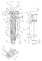
- the extruder 1 shown in the drawing figures is to be used for the preparation, ie for the plasticization of strand-like plastic material, for example in the form of round plastic wire, a melted strand emerging from the nozzle 20 of the extruder 1, which is intended, for example, to produce a welded connection between corresponding thermoplastic materials, the welded joint itself being prepared for achieving the connection by the air emerging from the hot air unit 2. So it is a high-speed small extruder.
- the extruder 1 itself is described in more detail below.
- the extruder 1 comprises the housing 3 and the screw 4, which is supported on the drive side against an axial bearing 16.
- the worm 4 is driven in rotation by a drive 5, which can be formed, for example, by a drilling machine.
- the screw 4 is constructed in sections. It has a plasticizing screw section 6, in which the material is melted, and a granulating screw section 7, in which the supplied material is crushed.
- the screw 4 is accommodated in corresponding sections 8, 9 of the housing 3.
- the pelletizing screw section 7 is designed with a larger diameter and is accommodated in a corresponding cylinder bore 10 in the housing 3 or the housing section 9.
- the plasticizing screw section 6 has a smaller outside diameter than the granulating screw section 7. It is also cylindrical on the outside and received in a corresponding cylindrical bore in the housing section 8. From Figure 1 is recognizable that the plasticizing screw section 6 extends into the cylindrical bore 10 for the granulating screw section 7.
- the plastic material to be pelletized and plasticized is introduced into the area of the pelletizing screw section 7 via a feed channel 12, which is designed as a bore. This can be seen from Figures 1 and 3.
- the wall 14 of the feed channel 12 approaches the outer contour 15 of the pelletizing screw section 7.
- the approach takes place in the direction of the plasticizing screw section 6.
- the angle of inclination ⁇ is chosen so that the bore axis 13 of the feed channel 12 crosses the screw contour of the pelletizing screw section 7.
- the size of the angle of inclination ⁇ for the bore axis 13 of the feed channel 12 and the angle of inclination ⁇ for the screw profile of the pelletizing screw section 7 are in a certain interaction in order to always ensure the aforementioned conditions.
- Particularly favorable cutting and pelletizing conditions result when the screw profile of the pelletizing screw section 7 is sawtooth-shaped, the steeper flank facing the plasticizing screw section 6.
- a transition between the feed channel 12 and the cylinder bore 10 in the housing section 9 is provided, which ensures that the free cross section between the outer contour 15 of the pelletizing screw section 7 and the feed channel 12 decreases.
- the wall 14 of the feed channel 12 approaches the outer contour 15 of the pelletizing screw section 7 with increasing progress towards the plasticizing screw section 6.
- At least part of the housing section 8 receiving the plasticizing screw section 6 is heatable.
- the housing section 8 is surrounded by a heater 19.
- the heater 19 is used in particular to ensure continuous melting conditions.
- the measurement of the current temperatures can serve both for heating control and for controlling the drive 5.
- the drive 5 can be coupled to the heating control in such a way that if the desired plasticizing temperature has not yet been reached, the drive 5 cannot be actuated and the screw 4 cannot be set in rotation.
- a cooling section 17 is provided between these two housing sections 8 and 9.
- the cooling section 17 is essentially formed by cooling ribs 18 which are cut into the outer contour of the housing 3. This also prevents that, due to a temperature exchange, heating of the housing section 9 can take place to such an extent that preheating of the inserted plastic strand occurs, which would impede clean granulation of the plastic strand in the region of the granulating screw section 7.
- the hot air unit 2 is designed as a heating cartridge, through which an air flow, which is generated by an external blower, is passed through hose and pipe lines becomes.
- This externally generated fan air flow can also be used to cool the housing section 9 receiving the pelletizing screw section 7.
- an annular channel 21 is provided in the housing section 9, specifically in the area of the axial bearing 16, which is cut as a recess in the housing section 9 and closed by a cover ring 22.
- the cover ring 22 has a connection piece with an inlet air opening 23, to which, for example, a hose which is connected to the external blower can be connected.
- the air is supplied to the hot air unit 2 via the hose into the supply air opening 23, the annular duct 21 and the supply air line 24 connected to it.
- the hot air unit 2 is provided with an outflow nozzle 25 which extends approximately to the area of the nozzle 20 of the extruder 1 and which serves to guide the hot air onto the prepared weld joint in order to melt material in the weld joint area, into which the strand of material emerging from the nozzle 20 can be deposited.
Landscapes
- Engineering & Computer Science (AREA)
- Mechanical Engineering (AREA)
- Physics & Mathematics (AREA)
- Thermal Sciences (AREA)
- Health & Medical Sciences (AREA)
- Clinical Laboratory Science (AREA)
- Processing And Handling Of Plastics And Other Materials For Molding In General (AREA)
- Extrusion Moulding Of Plastics Or The Like (AREA)
- Formation And Processing Of Food Products (AREA)
Applications Claiming Priority (2)
| Application Number | Priority Date | Filing Date | Title |
|---|---|---|---|
| DE3835250 | 1988-10-15 | ||
| DE3835250A DE3835250C1 (enExample) | 1988-10-15 | 1988-10-15 |
Publications (3)
| Publication Number | Publication Date |
|---|---|
| EP0364701A2 EP0364701A2 (de) | 1990-04-25 |
| EP0364701A3 EP0364701A3 (en) | 1990-11-07 |
| EP0364701B1 true EP0364701B1 (de) | 1994-07-06 |
Family
ID=6365258
Family Applications (1)
| Application Number | Title | Priority Date | Filing Date |
|---|---|---|---|
| EP89115788A Expired - Lifetime EP0364701B1 (de) | 1988-10-15 | 1989-08-26 | Extruder |
Country Status (4)
| Country | Link |
|---|---|
| US (1) | US5153008A (enExample) |
| EP (1) | EP0364701B1 (enExample) |
| AT (1) | ATE108128T1 (enExample) |
| DE (1) | DE3835250C1 (enExample) |
Families Citing this family (23)
| Publication number | Priority date | Publication date | Assignee | Title |
|---|---|---|---|---|
| DE4037020A1 (de) * | 1990-11-20 | 1992-05-21 | Koch Heinrich Plastmasch | Verfahren und vorrichtung zur regelung der temperatur der von einem schweissextruder plastifizierten kunststoffmasse |
| US5698237A (en) * | 1992-02-10 | 1997-12-16 | Bacher; Helmut | Apparatus for granulating synthetic plastics materials |
| DE4236281C2 (de) * | 1992-10-28 | 1995-11-23 | Munsch Kunststoff Schweistechn | Extruderschweißgerät |
| US5312224A (en) * | 1993-03-12 | 1994-05-17 | International Business Machines Corporation | Conical logarithmic spiral viscosity pump |
| US5358397A (en) * | 1993-05-10 | 1994-10-25 | L&L Products, Inc. | Apparatus for extruding flowable materials |
| DE9311705U1 (de) * | 1993-08-05 | 1993-10-14 | Wegener Gmbh, 52074 Aachen | Kunststoffschweißgerät |
| JPH0825451A (ja) * | 1994-07-11 | 1996-01-30 | Shinko Sellbick:Kk | 流動性材料の供給方法および供給装置 |
| EP0887116A3 (de) * | 1997-06-25 | 2001-04-04 | Peter Christian Dohle | Schweissextruder |
| DE19845766C1 (de) * | 1998-10-05 | 2000-07-06 | Munsch Kunststoff Schweistechn | Extruderschweißgerät |
| WO2000059707A1 (de) * | 1999-03-31 | 2000-10-12 | Barmag Ag | Vorrichtung zum extrudieren |
| JP3336296B2 (ja) * | 1999-07-23 | 2002-10-21 | 住友重機械工業株式会社 | 射出装置及びその制御方法 |
| DE29915768U1 (de) | 1999-09-08 | 2000-10-19 | Wegener Gmbh, 52074 Aachen | Extruderschweißeinrichtung |
| DE10007082C1 (de) * | 2000-02-16 | 2001-05-10 | Munsch Kunststoff Schweistechn | Extruderschweißgerät |
| USD520539S1 (en) * | 2004-05-28 | 2006-05-09 | Leister Process Technologies | Extrusion welder housing |
| EP1637234B2 (de) * | 2004-09-08 | 2012-06-13 | Leister Technologies AG | Handextruderschweissgerät |
| EP1634688B1 (de) * | 2004-09-08 | 2009-07-22 | Leister Process Technologies | Handextruderschweissgerät |
| US20060078635A1 (en) * | 2004-10-12 | 2006-04-13 | Franz-Josef Herz | Welding shoe, plastic welding shoe extruder, method for producing a plastic welded seam |
| DE102005022194B4 (de) * | 2005-05-13 | 2014-01-16 | Munsch Gmbh | Extruder, insbesondere Hand-Schweißextruder |
| ITPD20050156A1 (it) * | 2005-05-27 | 2006-11-28 | Ritmo Spa | Estrusore per la saldatura di componenti realizzati in materia plastica |
| DE202007014873U1 (de) | 2007-10-23 | 2008-11-27 | Wegener Gmbh | Kunststoffschweißgerät zum Verschweißen von Werkstücken aus Kunststoff |
| DE202010007466U1 (de) | 2010-06-01 | 2011-09-28 | Wegener International Gmbh | Handschweißgerät |
| USD695800S1 (en) * | 2013-05-07 | 2013-12-17 | Leister Technologies Ag | Extrusion welding machine |
| DE202013103383U1 (de) | 2013-07-26 | 2014-10-27 | Wegener International Gmbh | Handschweißgerät zum Verschweißen von Werkstücken aus thermoplastischem Kunststoff |
Family Cites Families (19)
| Publication number | Priority date | Publication date | Assignee | Title |
|---|---|---|---|---|
| DE899386C (de) * | 1945-02-01 | 1953-12-10 | Siemens Ag | Mit Foerderschnecke arbeitende Strangspritzmaschine fuer plastische Massen |
| DE840596C (de) * | 1950-10-12 | 1952-06-03 | Troester Maschf Paul | Vorrichtung fuer zwangslaeufige Beschickung von Schneckenpressen |
| DE938441C (de) * | 1953-04-25 | 1956-02-02 | Hermann Berstorff Maschb Ansta | Schneckenpresse fuer organische plastische Massen |
| US3656382A (en) * | 1970-08-28 | 1972-04-18 | Sund Borg Machines Corp | Rubber or plastic feeder-cutter |
| US3743252A (en) * | 1972-03-16 | 1973-07-03 | Gloucester Eng Co Inc | Air cooled extruder |
| DE2340772A1 (de) * | 1973-08-11 | 1975-02-27 | Schloemann Siemag Ag | Verfahren und einrichtung zum beschicken einer form mit treibmittelhaltigem, plastifizierten kunststoff |
| DE2351328A1 (de) * | 1973-10-12 | 1975-04-24 | Ver Foerderung Inst Kunststoff | Verfahren und einrichtung zum verarbeiten von zuvor unzerkleinerten thermoplastischen kunststoffabfaellen (altmaterial) in einschnecken-extrudern |
| DE2649045A1 (de) * | 1976-10-28 | 1978-05-03 | Gerhard Prof Dr Ing Schenkel | Einwellen-mehrstoff-extruder mit schneckengaengen |
| DE7724432U1 (de) * | 1977-08-05 | 1977-11-10 | Bucher-Guyer Ag Maschinenfabrik, Niederweningen, Zuerich (Schweiz) | Plastifiziermaschine zur verarbeitung bandfoermigen rohmaterials |
| DE2823171A1 (de) * | 1978-05-27 | 1979-11-29 | Erich Munsch | Schweissgeraet, insbesondere dicknaht- schweissgeraet |
| DE3046387C2 (de) * | 1980-12-09 | 1982-09-23 | Karl 7298 Loßburg Hehl | Spritzgießeinheit einer Kunststoff-Spritzgießmaschine mit einem Behälter für rieselfähiges Kunststoffmaterial |
| DE3221492C1 (de) * | 1982-06-07 | 1984-02-16 | Munsch Chemie-Pumpen GmbH, 5412 Ransbach-Baumbach | Schweißgerät, insbesondere Dicknaht-Schweißgerät |
| DE3227443C1 (de) * | 1982-07-22 | 1984-02-09 | Windmöller & Hölscher, 4540 Lengerich | Trichterstueck einer Einschneckenstrangpresse |
| JPS59115149A (ja) * | 1982-12-22 | 1984-07-03 | Fanuc Ltd | ならい制御方法 |
| US4561569A (en) * | 1984-01-12 | 1985-12-31 | Minnesota Mining And Manufacturing Company | Thermoplastic dispensing device with outlet cooling chamber |
| US4695240A (en) * | 1984-04-04 | 1987-09-22 | Allied Corporation | Apparatus for extruding small quantities of material |
| DE8612130U1 (de) * | 1986-05-02 | 1986-07-24 | Niederberg-Chemie GmbH, 4133 Neukirchen-Vluyn | Extrusionsschweißgerät |
| DE3808723C1 (en) * | 1988-03-16 | 1989-06-01 | Munsch Chemie-Pumpen Gmbh, 5412 Ransbach-Baumbach, De | Welding device |
| US4848915A (en) * | 1988-04-25 | 1989-07-18 | E. I. Du Pont De Nemours And Company | Process for metering color concentrates to thermoplastic polymer melts |
-
1988
- 1988-10-15 DE DE3835250A patent/DE3835250C1/de not_active Expired - Lifetime
-
1989
- 1989-08-26 AT AT89115788T patent/ATE108128T1/de not_active IP Right Cessation
- 1989-08-26 EP EP89115788A patent/EP0364701B1/de not_active Expired - Lifetime
-
1991
- 1991-09-23 US US07/764,056 patent/US5153008A/en not_active Expired - Fee Related
Also Published As
| Publication number | Publication date |
|---|---|
| EP0364701A3 (en) | 1990-11-07 |
| US5153008A (en) | 1992-10-06 |
| ATE108128T1 (de) | 1994-07-15 |
| DE3835250C1 (enExample) | 1990-05-10 |
| EP0364701A2 (de) | 1990-04-25 |
Similar Documents
| Publication | Publication Date | Title |
|---|---|---|
| EP0364701B1 (de) | Extruder | |
| EP0701505B1 (de) | Vorrichtung zum entgasen von thermoplastischem kunststoff | |
| EP1211045B1 (de) | Verfahren und Anlage zur Herstellung von faserverstärkten Kunststoffmassen | |
| DE69523651T2 (de) | Spritzgiessvorrichtung vom Vorplastifiziertyp | |
| EP2766161B1 (de) | Vorrichtung zum aufbereiten von kunststoffmaterial | |
| DE102019106873B4 (de) | Extruder | |
| DE3119840A1 (de) | "verfahren und vorrichtung zur rueckgewinnung von kunststoff aus kunststoffabfaellen" | |
| DE10356423B4 (de) | Extruder mit Materialeintrag durch das Gehäuse | |
| AT413354B (de) | Aufbereitungsvorrichtung für kunststoffmaterial | |
| EP2212090A1 (de) | Extruderschnecke für einen schneckenextruder | |
| EP3898160B1 (de) | Aufbereitungsanlage sowie verfahren zur aufbereitung von kunststoffmaterial für dessen wiederverwertung | |
| DE19928870A1 (de) | Einschnecken-Extruder | |
| DE2823171A1 (de) | Schweissgeraet, insbesondere dicknaht- schweissgeraet | |
| WO2019076982A1 (de) | Druckkopf für einen 3d-drucker | |
| DE102016120698B4 (de) | Extrusionsvorrichtung und Verfahren zum Betrieb einer Extrusionsvorrichtung | |
| EP1023948B1 (de) | Schweissgerät zum Verschweissen von Kunststoffwerkstücken | |
| DE3835251A1 (de) | Schneckenextruder zum plastifizieren von thermoplastischem kunststoffmaterial | |
| DE19952166B4 (de) | Schweißgerät für thermoplastische Kunststoffe | |
| DE19631182A1 (de) | Vorrichtung zum Granulieren | |
| DE102005022194B4 (de) | Extruder, insbesondere Hand-Schweißextruder | |
| DE102009015253A1 (de) | Handschweißextruder | |
| EP0887116A2 (de) | Schweissextruder | |
| DE29818757U1 (de) | Schweißgerät zum Verschweißen von Kunststoffwerkstücken | |
| DE4244312C1 (de) | Schneckenextruder | |
| DE202005018685U1 (de) | Handschweißextruder |
Legal Events
| Date | Code | Title | Description |
|---|---|---|---|
| PUAI | Public reference made under article 153(3) epc to a published international application that has entered the european phase |
Free format text: ORIGINAL CODE: 0009012 |
|
| AK | Designated contracting states |
Kind code of ref document: A2 Designated state(s): AT DE FR GB IT NL |
|
| PUAL | Search report despatched |
Free format text: ORIGINAL CODE: 0009013 |
|
| AK | Designated contracting states |
Kind code of ref document: A3 Designated state(s): AT DE FR GB IT NL |
|
| 17P | Request for examination filed |
Effective date: 19901029 |
|
| 17Q | First examination report despatched |
Effective date: 19920109 |
|
| RAP1 | Party data changed (applicant data changed or rights of an application transferred) |
Owner name: HEINRICH KOCH PLASTMASCHINEN GMBH |
|
| RAP3 | Party data changed (applicant data changed or rights of an application transferred) |
Owner name: HEINRICH KOCH PLASTMASCHINEN GMBH |
|
| RBV | Designated contracting states (corrected) |
Designated state(s): AT FR GB IT NL |
|
| REG | Reference to a national code |
Ref country code: DE Ref legal event code: 8566 |
|
| GRAA | (expected) grant |
Free format text: ORIGINAL CODE: 0009210 |
|
| ITF | It: translation for a ep patent filed | ||
| AK | Designated contracting states |
Kind code of ref document: B1 Designated state(s): AT FR GB IT NL |
|
| REF | Corresponds to: |
Ref document number: 108128 Country of ref document: AT Date of ref document: 19940715 Kind code of ref document: T |
|
| PGFP | Annual fee paid to national office [announced via postgrant information from national office to epo] |
Ref country code: GB Payment date: 19940808 Year of fee payment: 6 |
|
| GBT | Gb: translation of ep patent filed (gb section 77(6)(a)/1977) |
Effective date: 19940713 |
|
| ET | Fr: translation filed | ||
| PLBE | No opposition filed within time limit |
Free format text: ORIGINAL CODE: 0009261 |
|
| STAA | Information on the status of an ep patent application or granted ep patent |
Free format text: STATUS: NO OPPOSITION FILED WITHIN TIME LIMIT |
|
| 26N | No opposition filed | ||
| PG25 | Lapsed in a contracting state [announced via postgrant information from national office to epo] |
Ref country code: GB Effective date: 19950826 |
|
| GBPC | Gb: european patent ceased through non-payment of renewal fee |
Effective date: 19950826 |
|
| PG25 | Lapsed in a contracting state [announced via postgrant information from national office to epo] |
Ref country code: IT Free format text: LAPSE BECAUSE OF NON-PAYMENT OF DUE FEES Effective date: 20050826 |
|
| PGFP | Annual fee paid to national office [announced via postgrant information from national office to epo] |
Ref country code: NL Payment date: 20080820 Year of fee payment: 20 |
|
| PGFP | Annual fee paid to national office [announced via postgrant information from national office to epo] |
Ref country code: FR Payment date: 20080818 Year of fee payment: 20 Ref country code: AT Payment date: 20080821 Year of fee payment: 20 |
|
| NLV7 | Nl: ceased due to reaching the maximum lifetime of a patent |
Effective date: 20090826 |
|
| PG25 | Lapsed in a contracting state [announced via postgrant information from national office to epo] |
Ref country code: NL Free format text: LAPSE BECAUSE OF EXPIRATION OF PROTECTION Effective date: 20090826 |