EP0364701B1 - Extruder - Google Patents
Extruder Download PDFInfo
- Publication number
- EP0364701B1 EP0364701B1 EP89115788A EP89115788A EP0364701B1 EP 0364701 B1 EP0364701 B1 EP 0364701B1 EP 89115788 A EP89115788 A EP 89115788A EP 89115788 A EP89115788 A EP 89115788A EP 0364701 B1 EP0364701 B1 EP 0364701B1
- Authority
- EP
- European Patent Office
- Prior art keywords
- screw
- section
- housing
- plasticizing
- feed channel
- Prior art date
- Legal status (The legal status is an assumption and is not a legal conclusion. Google has not performed a legal analysis and makes no representation as to the accuracy of the status listed.)
- Expired - Lifetime
Links
Images
Classifications
-
- B—PERFORMING OPERATIONS; TRANSPORTING
- B29—WORKING OF PLASTICS; WORKING OF SUBSTANCES IN A PLASTIC STATE IN GENERAL
- B29C—SHAPING OR JOINING OF PLASTICS; SHAPING OF MATERIAL IN A PLASTIC STATE, NOT OTHERWISE PROVIDED FOR; AFTER-TREATMENT OF THE SHAPED PRODUCTS, e.g. REPAIRING
- B29C65/00—Joining or sealing of preformed parts, e.g. welding of plastics materials; Apparatus therefor
- B29C65/02—Joining or sealing of preformed parts, e.g. welding of plastics materials; Apparatus therefor by heating, with or without pressure
- B29C65/40—Applying molten plastics, e.g. hot melt
-
- B—PERFORMING OPERATIONS; TRANSPORTING
- B29—WORKING OF PLASTICS; WORKING OF SUBSTANCES IN A PLASTIC STATE IN GENERAL
- B29C—SHAPING OR JOINING OF PLASTICS; SHAPING OF MATERIAL IN A PLASTIC STATE, NOT OTHERWISE PROVIDED FOR; AFTER-TREATMENT OF THE SHAPED PRODUCTS, e.g. REPAIRING
- B29C48/00—Extrusion moulding, i.e. expressing the moulding material through a die or nozzle which imparts the desired form; Apparatus therefor
- B29C48/02—Small extruding apparatus, e.g. handheld, toy or laboratory extruders
-
- B—PERFORMING OPERATIONS; TRANSPORTING
- B29—WORKING OF PLASTICS; WORKING OF SUBSTANCES IN A PLASTIC STATE IN GENERAL
- B29C—SHAPING OR JOINING OF PLASTICS; SHAPING OF MATERIAL IN A PLASTIC STATE, NOT OTHERWISE PROVIDED FOR; AFTER-TREATMENT OF THE SHAPED PRODUCTS, e.g. REPAIRING
- B29C48/00—Extrusion moulding, i.e. expressing the moulding material through a die or nozzle which imparts the desired form; Apparatus therefor
- B29C48/03—Extrusion moulding, i.e. expressing the moulding material through a die or nozzle which imparts the desired form; Apparatus therefor characterised by the shape of the extruded material at extrusion
- B29C48/04—Particle-shaped
-
- B—PERFORMING OPERATIONS; TRANSPORTING
- B29—WORKING OF PLASTICS; WORKING OF SUBSTANCES IN A PLASTIC STATE IN GENERAL
- B29C—SHAPING OR JOINING OF PLASTICS; SHAPING OF MATERIAL IN A PLASTIC STATE, NOT OTHERWISE PROVIDED FOR; AFTER-TREATMENT OF THE SHAPED PRODUCTS, e.g. REPAIRING
- B29C48/00—Extrusion moulding, i.e. expressing the moulding material through a die or nozzle which imparts the desired form; Apparatus therefor
- B29C48/03—Extrusion moulding, i.e. expressing the moulding material through a die or nozzle which imparts the desired form; Apparatus therefor characterised by the shape of the extruded material at extrusion
- B29C48/06—Rod-shaped
-
- B—PERFORMING OPERATIONS; TRANSPORTING
- B29—WORKING OF PLASTICS; WORKING OF SUBSTANCES IN A PLASTIC STATE IN GENERAL
- B29C—SHAPING OR JOINING OF PLASTICS; SHAPING OF MATERIAL IN A PLASTIC STATE, NOT OTHERWISE PROVIDED FOR; AFTER-TREATMENT OF THE SHAPED PRODUCTS, e.g. REPAIRING
- B29C48/00—Extrusion moulding, i.e. expressing the moulding material through a die or nozzle which imparts the desired form; Apparatus therefor
- B29C48/25—Component parts, details or accessories; Auxiliary operations
- B29C48/285—Feeding the extrusion material to the extruder
- B29C48/288—Feeding the extrusion material to the extruder in solid form, e.g. powder or granules
- B29C48/2888—Feeding the extrusion material to the extruder in solid form, e.g. powder or granules in band or in strip form, e.g. rubber strips
-
- B—PERFORMING OPERATIONS; TRANSPORTING
- B29—WORKING OF PLASTICS; WORKING OF SUBSTANCES IN A PLASTIC STATE IN GENERAL
- B29C—SHAPING OR JOINING OF PLASTICS; SHAPING OF MATERIAL IN A PLASTIC STATE, NOT OTHERWISE PROVIDED FOR; AFTER-TREATMENT OF THE SHAPED PRODUCTS, e.g. REPAIRING
- B29C48/00—Extrusion moulding, i.e. expressing the moulding material through a die or nozzle which imparts the desired form; Apparatus therefor
- B29C48/25—Component parts, details or accessories; Auxiliary operations
- B29C48/36—Means for plasticising or homogenising the moulding material or forcing it through the nozzle or die
- B29C48/50—Details of extruders
- B29C48/505—Screws
- B29C48/53—Screws having a varying channel depth, e.g. varying the diameter of the longitudinal screw trunk
-
- B—PERFORMING OPERATIONS; TRANSPORTING
- B29—WORKING OF PLASTICS; WORKING OF SUBSTANCES IN A PLASTIC STATE IN GENERAL
- B29C—SHAPING OR JOINING OF PLASTICS; SHAPING OF MATERIAL IN A PLASTIC STATE, NOT OTHERWISE PROVIDED FOR; AFTER-TREATMENT OF THE SHAPED PRODUCTS, e.g. REPAIRING
- B29C48/00—Extrusion moulding, i.e. expressing the moulding material through a die or nozzle which imparts the desired form; Apparatus therefor
- B29C48/25—Component parts, details or accessories; Auxiliary operations
- B29C48/78—Thermal treatment of the extrusion moulding material or of preformed parts or layers, e.g. by heating or cooling
- B29C48/80—Thermal treatment of the extrusion moulding material or of preformed parts or layers, e.g. by heating or cooling at the plasticising zone, e.g. by heating cylinders
- B29C48/83—Heating or cooling the cylinders
- B29C48/832—Heating
-
- B—PERFORMING OPERATIONS; TRANSPORTING
- B29—WORKING OF PLASTICS; WORKING OF SUBSTANCES IN A PLASTIC STATE IN GENERAL
- B29C—SHAPING OR JOINING OF PLASTICS; SHAPING OF MATERIAL IN A PLASTIC STATE, NOT OTHERWISE PROVIDED FOR; AFTER-TREATMENT OF THE SHAPED PRODUCTS, e.g. REPAIRING
- B29C48/00—Extrusion moulding, i.e. expressing the moulding material through a die or nozzle which imparts the desired form; Apparatus therefor
- B29C48/25—Component parts, details or accessories; Auxiliary operations
- B29C48/78—Thermal treatment of the extrusion moulding material or of preformed parts or layers, e.g. by heating or cooling
- B29C48/80—Thermal treatment of the extrusion moulding material or of preformed parts or layers, e.g. by heating or cooling at the plasticising zone, e.g. by heating cylinders
- B29C48/83—Heating or cooling the cylinders
- B29C48/834—Cooling
-
- B—PERFORMING OPERATIONS; TRANSPORTING
- B29—WORKING OF PLASTICS; WORKING OF SUBSTANCES IN A PLASTIC STATE IN GENERAL
- B29C—SHAPING OR JOINING OF PLASTICS; SHAPING OF MATERIAL IN A PLASTIC STATE, NOT OTHERWISE PROVIDED FOR; AFTER-TREATMENT OF THE SHAPED PRODUCTS, e.g. REPAIRING
- B29C66/00—General aspects of processes or apparatus for joining preformed parts
- B29C66/01—General aspects dealing with the joint area or with the area to be joined
- B29C66/02—Preparation of the material, in the area to be joined, prior to joining or welding
- B29C66/024—Thermal pre-treatments
- B29C66/0242—Heating, or preheating, e.g. drying
-
- B—PERFORMING OPERATIONS; TRANSPORTING
- B29—WORKING OF PLASTICS; WORKING OF SUBSTANCES IN A PLASTIC STATE IN GENERAL
- B29C—SHAPING OR JOINING OF PLASTICS; SHAPING OF MATERIAL IN A PLASTIC STATE, NOT OTHERWISE PROVIDED FOR; AFTER-TREATMENT OF THE SHAPED PRODUCTS, e.g. REPAIRING
- B29C66/00—General aspects of processes or apparatus for joining preformed parts
- B29C66/80—General aspects of machine operations or constructions and parts thereof
- B29C66/84—Specific machine types or machines suitable for specific applications
- B29C66/861—Hand-held tools
Definitions
- the invention relates to a welding extruder for plasticizing a plastic wire, in particular a round wire, made of thermoplastic material, with a housing and a screw rotatably arranged in the housing, the screw having a shorter section with a sawtooth-shaped profile for drawing in the plastic wire, and one for this Reduced in diameter, longer and heated over at least part of its length plasticizing section for plasticizing the plastic wire, with a feed channel in the housing, which is open to the outer contour of the profile of the shorter section of the screw and via which the plastic wire is in contact with this section, and with a drive for the screw.
- Such a welding extruder is described in DE-U-8 612 130.
- a slot in the housing of the welding extruder which serves as a feed channel.
- the plastic wire to be drawn in and melted is guided parallel to the outer contour of the auger section which is enlarged in diameter.
- the sawtooth-shaped profile of the screw section engages only in the surface of the plastic wire, since it is pressed against the outer contour by a lever.
- the lever is used for thickness compensation.
- the wire is then deflected into an obliquely running bore which opens into the housing section in which the plasticizing screw section is recorded. Because of this arrangement, shearing and granulation take place in the plasticizing screw section when the plastic wire passes into the screw flights.
- DE-C-3221492 describes an extruder for plasticizing plastic material which is placed in a weld joint, a thickness compensation slide being provided to adapt to different material thicknesses of the supplied plastic material.
- the screw section assigned to the feed channel is designed only as a feed section, i. H. the material is first comminuted and then plasticized in the subsequent screw section, which is designed as a conveying and comminuting member and forms the longer screw section.
- the feed section is only designed as a screw.
- the screw in several parts, ie to have several sections, one of which is designed, for example, as a plasticizing screw section and the other as a feed section.
- a feed channel opens, through which the plastic material to be processed, which can be in the form of a string, for example in the form of a ribbon, is introduced and drawn in.
- this feed screw section for example, cylindrical or conical.
- the screw consisting of the two sections is driven by a drive, which is preferably arranged coaxially.
- the worm itself is usually supported on an axial bearing on the drive side.
- the object of the invention is to create a high-speed welding extruder with which improved plasticization is ensured even with a short overall length of the screw and a largely homogeneous, plasticized strand is produced.
- the feed channel is designed as a bore in the housing section receiving the shorter section of the screw and opens into the cylinder bore for receiving the shorter section of the screw, the axis of the feed channel crossing the screw axis at a distance and the feed channel runs in the direction of the plasticizing screw section of the screw such that the free cross-section between the wall of the feed channel and the outer contour of the granulating screw section decreases, so that granulation of the inserted plastic wire takes place in the shorter section of the screw and that the longer plasticizing section axially into the shorter section the screw-receiving cylinder bore protrudes.
- the advantage of this training is that already in the The area which serves to draw in the plastic material to be plasticized is granulated so that the entire length is available for melting the plastic material in the subsequent plasticizing screw section. This results in an extremely short overall length for the screw and thus for the extruder. This favors use in portable devices which are used to prepare a plastic strand for storage in a weld joint.
- the provided rigid feed channel brings the plastic strand directly to the pelletizing screw section and, moreover, the inclined arrangement means that the pelletizing process is carried out in the shortest possible way.
- the design and guidance of the feed channel ensures that there is no danger of the strand tearing off in any operating state, but that there is continuous feed and granulation. Furthermore, the diameter of the pelletizing screw section and the guidance of the pelletizing screw section up to the cylinder bore for receiving the pelletizing screw section ensure a safe and continuous transfer of the granulated material into the pelletizing screw section.
- a cooling section is provided between the heatable housing section receiving the plasticizing screw section and the housing section having the cylinder bore for the shorter pelletizing section of the screw.
- the cooling section preferably consists of cooling fins. These are cut, for example, into the outer contour of the housing.
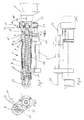
- the extruder 1 shown in the drawing figures is to be used for the preparation, ie for the plasticization of strand-like plastic material, for example in the form of round plastic wire, a melted strand emerging from the nozzle 20 of the extruder 1, which is intended, for example, to produce a welded connection between corresponding thermoplastic materials, the welded joint itself being prepared for achieving the connection by the air emerging from the hot air unit 2. So it is a high-speed small extruder.
- the extruder 1 itself is described in more detail below.
- the extruder 1 comprises the housing 3 and the screw 4, which is supported on the drive side against an axial bearing 16.
- the worm 4 is driven in rotation by a drive 5, which can be formed, for example, by a drilling machine.
- the screw 4 is constructed in sections. It has a plasticizing screw section 6, in which the material is melted, and a granulating screw section 7, in which the supplied material is crushed.
- the screw 4 is accommodated in corresponding sections 8, 9 of the housing 3.
- the pelletizing screw section 7 is designed with a larger diameter and is accommodated in a corresponding cylinder bore 10 in the housing 3 or the housing section 9.
- the plasticizing screw section 6 has a smaller outside diameter than the granulating screw section 7. It is also cylindrical on the outside and received in a corresponding cylindrical bore in the housing section 8. From Figure 1 is recognizable that the plasticizing screw section 6 extends into the cylindrical bore 10 for the granulating screw section 7.
- the plastic material to be pelletized and plasticized is introduced into the area of the pelletizing screw section 7 via a feed channel 12, which is designed as a bore. This can be seen from Figures 1 and 3.
- the wall 14 of the feed channel 12 approaches the outer contour 15 of the pelletizing screw section 7.
- the approach takes place in the direction of the plasticizing screw section 6.
- the angle of inclination ⁇ is chosen so that the bore axis 13 of the feed channel 12 crosses the screw contour of the pelletizing screw section 7.
- the size of the angle of inclination ⁇ for the bore axis 13 of the feed channel 12 and the angle of inclination ⁇ for the screw profile of the pelletizing screw section 7 are in a certain interaction in order to always ensure the aforementioned conditions.
- Particularly favorable cutting and pelletizing conditions result when the screw profile of the pelletizing screw section 7 is sawtooth-shaped, the steeper flank facing the plasticizing screw section 6.
- a transition between the feed channel 12 and the cylinder bore 10 in the housing section 9 is provided, which ensures that the free cross section between the outer contour 15 of the pelletizing screw section 7 and the feed channel 12 decreases.
- the wall 14 of the feed channel 12 approaches the outer contour 15 of the pelletizing screw section 7 with increasing progress towards the plasticizing screw section 6.
- At least part of the housing section 8 receiving the plasticizing screw section 6 is heatable.
- the housing section 8 is surrounded by a heater 19.
- the heater 19 is used in particular to ensure continuous melting conditions.
- the measurement of the current temperatures can serve both for heating control and for controlling the drive 5.
- the drive 5 can be coupled to the heating control in such a way that if the desired plasticizing temperature has not yet been reached, the drive 5 cannot be actuated and the screw 4 cannot be set in rotation.
- a cooling section 17 is provided between these two housing sections 8 and 9.
- the cooling section 17 is essentially formed by cooling ribs 18 which are cut into the outer contour of the housing 3. This also prevents that, due to a temperature exchange, heating of the housing section 9 can take place to such an extent that preheating of the inserted plastic strand occurs, which would impede clean granulation of the plastic strand in the region of the granulating screw section 7.
- the hot air unit 2 is designed as a heating cartridge, through which an air flow, which is generated by an external blower, is passed through hose and pipe lines becomes.
- This externally generated fan air flow can also be used to cool the housing section 9 receiving the pelletizing screw section 7.
- an annular channel 21 is provided in the housing section 9, specifically in the area of the axial bearing 16, which is cut as a recess in the housing section 9 and closed by a cover ring 22.
- the cover ring 22 has a connection piece with an inlet air opening 23, to which, for example, a hose which is connected to the external blower can be connected.
- the air is supplied to the hot air unit 2 via the hose into the supply air opening 23, the annular duct 21 and the supply air line 24 connected to it.
- the hot air unit 2 is provided with an outflow nozzle 25 which extends approximately to the area of the nozzle 20 of the extruder 1 and which serves to guide the hot air onto the prepared weld joint in order to melt material in the weld joint area, into which the strand of material emerging from the nozzle 20 can be deposited.
Landscapes
- Engineering & Computer Science (AREA)
- Mechanical Engineering (AREA)
- Physics & Mathematics (AREA)
- Thermal Sciences (AREA)
- Health & Medical Sciences (AREA)
- Clinical Laboratory Science (AREA)
- Processing And Handling Of Plastics And Other Materials For Molding In General (AREA)
- Extrusion Moulding Of Plastics Or The Like (AREA)
- Formation And Processing Of Food Products (AREA)
Abstract
Description
Die Erfindung betrifft einen Schweißextruder zum Plastifizieren eines Kunststoffdrahtes, insbesondere eines Runddrahtes, aus thermoplastischem Kunststoff, mit einem Gehäuse und einer im Gehäuse drehbar angeordnete Schnecke, wobei die Schnecke einen kürzeren Abschnitt mit einem im Querschnitt sägezahnförmigen Profil zum Einziehen des Kunststoffdrahtes aufweist, und einen dazu im Durchmesser verringerten, längeren und über zumindest einen Teil seiner Länge beheizbaren Plastifizierabschnitt zum Plastifizieren des Kunststoffdrahtes aufweist, mit einem Einzugskanal im Gehäuse, der zur Außenkontur des Profils des kürzeren Abschnitts der Schnecke offen ist und über welchen der Kunststoffdraht in Kontakt mit diesem Abschnitt ist, und mit einem Antrieb für die Schnecke.The invention relates to a welding extruder for plasticizing a plastic wire, in particular a round wire, made of thermoplastic material, with a housing and a screw rotatably arranged in the housing, the screw having a shorter section with a sawtooth-shaped profile for drawing in the plastic wire, and one for this Reduced in diameter, longer and heated over at least part of its length plasticizing section for plasticizing the plastic wire, with a feed channel in the housing, which is open to the outer contour of the profile of the shorter section of the screw and via which the plastic wire is in contact with this section, and with a drive for the screw.
Ein solcher Schweißextruder ist in der DE-U-8 612 130 beschrieben. Im Gehäuse des Schweißextruders ist ein Schlitz vorhanden, welcher als Einzugskanal dient. Der einzuziehende und aufzuschmelzende Kunststoffdraht wird parallel zur Außenkontur des im Durchmesser vergrößerten Einziehschneckenabschnittes geführt. Das sägezahnförmige Profil des Einziehschneckenabschnittes greift dabei nur in die Oberfläche des Kunststoffdrahtes ein, da er über einen Hebel an die Außenkontur angedrückt wird. Der Hebel dient zum Dickenausgleich. Anschließend wird der Draht in eine schräg verlaufende Bohrung umgelenkt, die in dem Gehäuseabschnitt mündet, in dem der Plastifizierschneckenabschnitt aufgenommen ist. Aufgrund dieser Anordnung findet ein Abscheren und Granulieren im Plastifizierschneckenabschnitt beim Übertritt des Kunststoffdrahtes in die Gänge der Schnecke statt.Such a welding extruder is described in DE-U-8 612 130. There is a slot in the housing of the welding extruder, which serves as a feed channel. The plastic wire to be drawn in and melted is guided parallel to the outer contour of the auger section which is enlarged in diameter. The sawtooth-shaped profile of the screw section engages only in the surface of the plastic wire, since it is pressed against the outer contour by a lever. The lever is used for thickness compensation. The wire is then deflected into an obliquely running bore which opens into the housing section in which the plasticizing screw section is recorded. Because of this arrangement, shearing and granulation take place in the plasticizing screw section when the plastic wire passes into the screw flights.
In der DE-C-3221492 ist ein Extruder für die Plastifizierung von Kunststoffmaterial, welches in eine Schweißfuge abgelegt wird, beschrieben, wobei zur Anpassung an verschiedene Materialstärken des zugeführten Kunststoffmateriales ein Dickenausgleichschieber vorgesehen ist. Der dem Einzugskanal zugeordnete Schneckenabschnitt ist nur als Einzugsabschnitt ausgebildet, d. h. das Material wird erst in dem anschließenden Schneckenabschnitt, welcher als Förder- und Zerkleinerungsorgan ausgebildet ist und den längeren Schneckenabschnitt bildet, zerkleinert und anschließend plastifiziert. Der Einzugsabschnitt ist lediglich als Förderschraube ausgebildet.DE-C-3221492 describes an extruder for plasticizing plastic material which is placed in a weld joint, a thickness compensation slide being provided to adapt to different material thicknesses of the supplied plastic material. The screw section assigned to the feed channel is designed only as a feed section, i. H. the material is first comminuted and then plasticized in the subsequent screw section, which is designed as a conveying and comminuting member and forms the longer screw section. The feed section is only designed as a screw.
Bei Extrudern ist es allgemein bekannt, die Schnecke mehrteilig aufzubauen, d. h. mehrere Abschnitte aufweisen zu lassen, von denen einer beispielsweise als Plastifizierschneckenabschnitt und der andere als Einzugsabschnitt ausgebildet ist. In den Bereich des Einzugsabschnittes mündet ein Einzugskanal, durch den das zu verarbeitende Kunststoffmaterial, welches strangförmig, beispielsweise in Form von Bändchen, ausgebildet sein kann, eingeführt und eingezogen wird. Dabei ist es bekannt, diesen Einzugsschneckenabschnitt beispielsweise zylindrisch oder aber konisch zu gestalten. Die aus den beiden Abschnitten bestehende Schnecke wird von einem Antrieb, der bevorzugt gleichachsig angeordnet ist, angetrieben. Die Schnecke selbst stützt sich in der Regel antriebsseitig an einem Axiallager ab.In the case of extruders, it is generally known to construct the screw in several parts, ie to have several sections, one of which is designed, for example, as a plasticizing screw section and the other as a feed section. In the area of the feed section, a feed channel opens, through which the plastic material to be processed, which can be in the form of a string, for example in the form of a ribbon, is introduced and drawn in. It is known to make this feed screw section, for example, cylindrical or conical. The screw consisting of the two sections is driven by a drive, which is preferably arranged coaxially. The worm itself is usually supported on an axial bearing on the drive side.
Es hat sich gezeigt, daß bei kleineren Extrudern mit einer solchen Gestaltung die Aufschmelzung des Materials nicht optimal erfolgt. Insbesondere wird kein homogener, aus der Düse austretender plastifizierter Strang erzeugt. Inhomogenitäten bewirken eine Qualitätsminderung des aufgeschmolzenen bzw. plastifizierten Materiales und darüberhinaus, wird dadurch bei der Verbindung von thermoplastischen Kunststoffelementen, durch Schweißen eine verminderte Schweißnahtqualität erreicht.It has been shown that in the case of smaller extruders with such a design, the melting of the material does not take place optimally. In particular, no homogeneous plasticized strand emerging from the nozzle is produced. Inhomogeneities cause a reduction in the quality of the melted or plasticized material and, moreover, a reduced weld seam quality is achieved when welding thermoplastic plastic elements.
Hiervon ausgehend liegt der Erfindung die Aufgabe zugrunde, einen schnelllaufenden Schweißextruder zu schaffen, mit dem auch bei kurzer Gesamtlänge der Schnecke eine verbesserte Plastifizierung gewährleistet ist und ein weitestgehend homogen, plastifizierter Strang erzeugt wird.Proceeding from this, the object of the invention is to create a high-speed welding extruder with which improved plasticization is ensured even with a short overall length of the screw and a largely homogeneous, plasticized strand is produced.
Diese Aufgabe wird erfindungsgemäß dadurch gelöst, daß der Einzugskanal als Bohrung in dem den kürzeren Abschnitt der Schnecke aufnehmenden Gehäuseabschnitt ausgebildet ist und in deren Zylinderbohrung zur Aufnahme des kürzeren Abschnittes der Schnecke mündet, wobei die Achse des Einzugskanals die Schneckenachse derart mit Abstand kreuzt und der Einzugskanal derart in Richtung auf den Plastifizierschneckenabschnitt der Schnecke verläuft, daß der freie Querschnitt zwischen der Wandung des Einzugskanals und der Außenkontur des Granulierschneckenabschnittes abnimmt, so daß eine Granulierung des eingeführten Kunststoffdrahtes im kürzeren Abschnitt der Schnecke erfolgt und daß der längere Plastifizierabschnitt axial in die den kürzeren Abschnitt der Schnecke aufnehmende Zylinderbohrung hineinragt.This object is achieved in that the feed channel is designed as a bore in the housing section receiving the shorter section of the screw and opens into the cylinder bore for receiving the shorter section of the screw, the axis of the feed channel crossing the screw axis at a distance and the feed channel runs in the direction of the plasticizing screw section of the screw such that the free cross-section between the wall of the feed channel and the outer contour of the granulating screw section decreases, so that granulation of the inserted plastic wire takes place in the shorter section of the screw and that the longer plasticizing section axially into the shorter section the screw-receiving cylinder bore protrudes.
Von Vorteil bei dieser Ausbildung ist, daß schon in dem Bereich, der dem Einzug des zu plastifizierenden Kunststoffmaterials dient, eine Granulierung erfolgt, so daß in dem anschließenden Plastifizierschneckenabschnitt die gesamte Länge für das Aufschmelzen des Kunststoffmateriales zur Verfügung steht. Hierdurch wird eine extrem kurze Baulänge für die Schnecke und damit für den Extruder erreicht. Dies begünstigt den Einsatz bei tragbaren Geräten, welche zur Aufbereitung eines Kunststoffstranges für die Ablage in eine Schweißfuge dienen. Der vorgesehene starre Einzugskanal bewirkt eine direkte Hinführung des Kunststoffstranges auf den Granulierschneckenabschnitt und darüberhinaus bewirkt die geneigte Anordnung, daß auf kürzestem Wege der Granuliervorgang durchgeführt wird.The advantage of this training is that already in the The area which serves to draw in the plastic material to be plasticized is granulated so that the entire length is available for melting the plastic material in the subsequent plasticizing screw section. This results in an extremely short overall length for the screw and thus for the extruder. This favors use in portable devices which are used to prepare a plastic strand for storage in a weld joint. The provided rigid feed channel brings the plastic strand directly to the pelletizing screw section and, moreover, the inclined arrangement means that the pelletizing process is carried out in the shortest possible way.
Durch die Ausbildung und Führung des Einzugskanals wird erreicht, daß in keinem Betriebszustand die Gefahr des Abreißens des Stranges gegeben ist, sondern kontinuierlich ein Einzug und eine Granulierung stattfindet. Ferner wird durch die im Durchmesser vergrößerte Ausbildung des Granulierschneckenabschnittes und die Führung des Plastifizierschneckenabschnittes bis in die Zylinderbohrung für die Aufnahme des Granulierschneckenabschnittes eine sichere und kontinuierliche Überführung des granulierten Materiales in den Plastifizierschneckenabschnitt gewährleistet.The design and guidance of the feed channel ensures that there is no danger of the strand tearing off in any operating state, but that there is continuous feed and granulation. Furthermore, the diameter of the pelletizing screw section and the guidance of the pelletizing screw section up to the cylinder bore for receiving the pelletizing screw section ensure a safe and continuous transfer of the granulated material into the pelletizing screw section.
Besonders günstige Schneidverhältnisse und Granulierergebnisse werden dadurch erreicht, daß der Steigungswinkel des sägezahnförmigen Profils des kürzeren Abschnittes der Schnecke 3° bis 8° und der Neigungswinkel, mit dem die Achse des Einzugskanals die Schneckenachse kreuzt, 45° bis 55° beträgt.Particularly favorable cutting conditions and granulation results are achieved in that the pitch angle of the sawtooth-shaped profile of the shorter section of the screw is 3 ° to 8 ° and the angle of inclination with which the axis of the feed channel crosses the screw axis is 45 ° to 55 °.
Ferner wird für Extruder höherer Leistung vorgeschlagen, zwei umfangsversetzte Einzugskanäle vorzusehen.It is also proposed for higher-performance extruders that provide two circumferentially offset feed channels.
Zur Erzielung einer klaren Trennung zwischen den Funktionen der beiden Schneckenabschnitte ist vorgesehen, zwischen dem den Plastifizierschneckenabschnitt aufnehmenden, beheizbaren Gehäuseabschnitt und dem die Zylinderbohrung für den kürzeren Granulierabschnitt der Schnecke aufweisenden Gehäuseabschnitt einen Kühlabschnitt anzuordnen.To achieve a clear separation between the functions of the two screw sections, a cooling section is provided between the heatable housing section receiving the plasticizing screw section and the housing section having the cylinder bore for the shorter pelletizing section of the screw.
Hierdurch wird gewährleistet, daß im Bereich des Einzugs kein Plastifizieren eintritt, welches die Zuführung des Materials behindern würde, weil beispielsweise schon eine gewisse Erweichung eintreten könnte.This ensures that no plasticizing occurs in the area of the feeder, which would hinder the feeding of the material because, for example, a certain softening could already occur.
Bevorzugt besteht der Kühlabschnitt aus Kühlrippen. Diese sind beispielsweise in die Gehäuseaußenkontur eingeschnitten.The cooling section preferably consists of cooling fins. These are cut, for example, into the outer contour of the housing.
Es zeigt
- Fig. 1
- einen Längsschnitt durch den erfindungsgemäßen Schweißextruder mit einem zusätzlichen Heißluftaggregat.
- Fig. 2
- eine Draufsicht zu
Figur 1 und - Fig. 3
- einen Schnitt A-A gemäß
Figur 1, wobei der Einzugskanal in die Zeichenebene hineingeklappt ist.
- Fig. 1
- a longitudinal section through the welding extruder according to the invention with an additional hot air unit.
- Fig. 2
- a plan view of Figure 1 and
- Fig. 3
- a section AA according to Figure 1, wherein the feed channel is folded into the plane of the drawing.
Der in den Zeichnungsfiguren dargestellte Extruder 1 soll zur Vorbereitung, d. h. zur Plastifizierung von strangförmigem Kunststoffmaterial, beispielsweise in Form von Kunststoffrunddraht, eingesetzt werden, wobei aus der Düse 20 des Extruders 1 ein aufgeschmolzener Strang austritt, welcher beispielsweise zur Herstellung einer Schweißverbindung zwischen entsprechenden thermoplastischen Kunststoffmaterialien dienen soll, wobei die Schweißfuge selbst durch die aus dem Heißluftaggregat 2 austretende Luft zur Erzielung der Verbindung vorbereitet ist. Es handelt sich also um einen schnellaufenden Kleinextruder.The
Zunächst wird nachfolgend der Extruder 1 selbst im Einzelnen näher beschrieben. Der Extruder 1 umfaßt das Gehäuse 3 und die Schnecke 4, welche antriebsseitig gegen ein Axiallager 16 abgestützt ist. Die Schnecke 4 wird über einen Antrieb 5 drehend angetrieben, der beispielsweise von einer Bohrmaschine gebildet sein kann.First, the
Die Schnecke 4 ist abschnittsweise aufgebaut. Sie weist einen Plastifizierschneckenabschnitt 6, in dem das Material aufgeschmolzen wird, und einen Granulierschneckenabschnitt 7 auf, in dem das zugeführte Material zerkleinert wird.The
Die Schnecke 4 ist in entsprechenden Abschnitten 8, 9 des Gehäuses 3 aufgenommen. So ist beispielsweise der Granulierschneckenabschnitt 7 mit einem größeren Durchmesser ausgeführt und in einer entsprechenden Zylinderbohrung 10 des Gehäuses 3 bzw. des Gehäuseabschnitts 9 aufgenommen. Der Plastifizierschneckenabschnitt 6 besitzt einen kleineren Außendurchmesser als der Granulierschneckenabschnitt 7. Er ist ebenfalls außen zylindrisch und in einer entsprechend zylindrischen Bohrung des Gehäuseabschnittes 8 aufgenommen. Aus Figur 1 ist erkennbar, daß der Plastifizierschneckenabschnitt 6 bis in die zylindrische Bohrung 10 für den Granulierschneckenabschnitt 7 hineinragt. Das zu granulierende und plastifizierende Kunststoffmaterial wird in den Bereich des Granulierschneckenabschnittes 7 über einen Einzugskanal 12, der als Bohrung ausgebildet ist, eingeführt. Dieser ist aus den Figuren 1 und 3 erkenntlich. Er ist geneigt zur Schneckenachse 11 verlaufend angeordnet und der Neigungswinkel der Bohrungsachse 13 ist mit α bezeichnet. Wie aus Figur 3 ersichtlich ist, nähert sich die Wandung 14 des Einzugskanals 12 der Außenkontur 15 des Granulierschneckenabschnittes 7 an. Die Annäherung erfolgt in Richtung auf den Plastifizierschneckenabschnitt 6 zu. Der Neigungswinkel α ist so gewählt, daß die Bohrungsachse 13 des Einzugskanals 12 die Schneckenkontur des Granulierschneckenabschnittes 7 kreuzt. Aus diesem Grunde stehen die Größe des Neigungswinkels α für die Bohrungsachse 13 des Einzugskanals 12 und des Steigungswinkels β für das Schneckenprofil des Granulierschneckenabschnittes 7 in einer bestimmten Wechselwirkung, um die vorgenannten Verhältnisse stets zu gewährleisten. Besonders günstige Schneid- und Granulierverhältnisse ergeben sich dann, wenn das Schneckenprofil des Granulierschneckenabschnittes 7 Sägezahnförmig ausgebildet ist, wobei die steiler verlaufende Flanke dem Plastifizierschneckenabschnitt 6 zugerichtet ist.The
Um ein frühzeitiges Abreißen des eingeführten Kunststoffstranges zu vermeiden, ist ein Übergang zwischen dem Einzugskanal 12 und der Zylinderbohrung 10 im Gehäuseabschnitt 9 vorgesehen, welcher gewährleistet, daß der freie Querschnitt zwischen der Außenkontur 15 des Granulierschneckenabschnittes 7 und dem Einzugskanal 12 abnimmt. Aus diesem Grunde, nähert sich die Wandung 14 des Einzugskanals 12 mit fortschreitender Annäherung auf den Plastifizierschneckenabschnitt 6 der Außenkontur 15 des Granulierschneckenabschnittes 7 an. Zumindest ein Teil des den Plastifizierschneckenabschnitt 6 aufnehmenden Gehäuseabschnittes 8 ist beheizbar ausgebildet. Hierzu ist der Gehäuseabschnitt 8 von einer Heizung 19 umgeben. Die Heizung 19 dient insbesondere dazu, kontinuierliche Aufschmelzverhältnisse zu gewährleisten. So kann die Messung der aktuellen Temperaturen sowohl zur Heizungssteuerung als auch zur Steuerung des Antriebes 5 dienen. Beispielsweise kann der Antrieb 5 so mit der Heizungssteuerung gekoppelt sein, daß dann, wenn die gewünschte Plastifizierungstemperatur noch nicht erreicht ist, der Antrieb 5 nicht betätigt werden kann und damit die Schnecke 4 auch nicht in Rotation versetzt werden kann.In order to avoid premature tearing of the inserted plastic strand, a transition between the
Um zu verhindern, daß ein Temperaturaustausch zwischen den beiden Gehäuseabschnitten 8 und 9 erfolgt, ist ein Kühlabschnitt 17 zwischen diesen beiden Gehäuseabschnitten 8 und 9 vorgesehen. Der Kühlabschnitt 17 wird im wesentlichen durch Kühlrippen 18 gebildet, die in die Außenkontur des Gehäuses 3 eingeschnitten sind. Hierdurch wird auch verhindert, daß aufgrund eines Temperaturaustausches eine Erwärmung des Gehäuseabschnittes 9 soweit erfolgen kann, daß eine Vorerwärmung des eingeführten Kunststoffstranges eintritt, was eine saubere Granulierung des Kunststoffstranges im Bereich des Granulierschneckenabschnittes 7 behindern würde.In order to prevent a temperature exchange between the two
Das Heißluftaggregat 2 ist als Heizpatrone ausgebildet, durch welche ein Luftstrom, der durch ein externes Gebläse erzeugt wird, über Schlauch- und Rohrleitungen hindurchgeleitet wird. Dieser extern erzeugte Gebläseluftstrom kann außerdem noch zur Kühlung des den Granulierschneckenabschnitt 7 aufnehmenden Gehäuseabschnittes 9 genutzt werden. So ist beispielsweise aus den Figuren 1 und 2 ersichtlich, daß im Gehäuseabschnitt 9 und zwar im Bereich des Axiallagers 16 ein Ringkanal 21 vorgesehen ist, der als Vertiefung in den Gehäuseabschnitt 9 eingeschnitten und durch einen Abdeckring 22 verschlossen ist. Der Abdeckring 22 besitzt einen Stutzen mit einer Zuluftöffnung 23, an welchen beispielsweise ein Schlauch, der mit dem externen Gebläse verbunden ist, anschließbar ist. Die Luft wird über den Schlauch in die Zuluftöffnung 23, den Ringkanal 21 und die daran angeschlossene Zuluftleitung 24 dem Heißluftaggregat 2 zugeführt.The
Das Heißluftaggregat 2 ist mit einer Ausströmdüse 25 versehen, die etwa bis in den Bereich der Düse 20 des Extruders 1 reicht und die dazu dient, die Heißluft auf die vorbereitete Schweißfuge zu leiten, um daß Material im Bereich der Schweißfuge anzuschmelzen, in welche dann der aus der Düse 20 austretende Materialstrang ablegbar ist.The
Claims (5)
- A welding extruder for plasticizing a plastic wire feedstock, especially a round wire feedstock, consisting of thermoplastic plastics; having a housing (3) and screw (4) rotatably arranged in the housing, the screw (4) comprising a shorter portion (7) having a profile with a saw-tooth-shaped cross-section for drawing in the plastic wire feedstock, and a longer plasticizing portion (6) whose diameter is reduced relative to said shorter portion (7), which is heatable along at least part of its length and used for plasticising the plastic wire feedstock; having an feed channel (12) in the housing (3) which is open towards the outer contour of the profile of the shorter portion (7) of the screw (4) and by means of which the plastic wire feedstock is in contact with said portion (7); and having a drive (5) for the screw (4),
characterised in
that the feed channel (12) is provided in the form of a bore in the housing portion (9) accommodating the shorter portion (7) of the screw (4) and terminates in its cylindrical bore (10) for accommodating the shorter portion (7) of the screw (4), the axis (13) of the feed channel (12) intersecting the screw axis (10), and the feed channel (12) extending in the direction of the plasticizing screw portion (6) of the screw (4), in such a manner that the free cross-section between the wall of the feed channel (12) and the outer contour (11) of the granulating screw portion (7) decreases so that the plastic wire feedstock as introduced is granulated in the shorter portion (7) of the screw (4); and that the longer plasticizing portion (6) axially extends into the cylindrical bore (10) accommodating the shorter portion (7) of the screw (4). - A welding extruder according to claim 1,
characterised in
that the pitch angle (B) of the saw-tooth-shaped profile of the shorter portion (7) of the screw (4) amounts to 3° to 8° and that the angle of inclination (A) at which the axis (13) of the feed channel (12) intersects the screw axis (11) amounts to 45° to 55°. - A welding extruder according to claim 1,
characterised in
that there are provided two circumferentially offset feed channels (12). - A welding extruder according to claim 1,
characterised in
that a cooling portion (17) is arranged between the heatable housing portion (8) accommodating the plasticizing portion (6) and the housing portion (9) comprising the cylindrical bore (10) for the shorter portion (7) of the screw (4). - A welding extruder according to claim 4,
characterised in
that the cooling portion (17) consists of cooling ribs (18).
Applications Claiming Priority (2)
| Application Number | Priority Date | Filing Date | Title |
|---|---|---|---|
| DE3835250A DE3835250C1 (en) | 1988-10-15 | 1988-10-15 | |
| DE3835250 | 1988-10-15 |
Publications (3)
| Publication Number | Publication Date |
|---|---|
| EP0364701A2 EP0364701A2 (en) | 1990-04-25 |
| EP0364701A3 EP0364701A3 (en) | 1990-11-07 |
| EP0364701B1 true EP0364701B1 (en) | 1994-07-06 |
Family
ID=6365258
Family Applications (1)
| Application Number | Title | Priority Date | Filing Date |
|---|---|---|---|
| EP89115788A Expired - Lifetime EP0364701B1 (en) | 1988-10-15 | 1989-08-26 | Extruder |
Country Status (4)
| Country | Link |
|---|---|
| US (1) | US5153008A (en) |
| EP (1) | EP0364701B1 (en) |
| AT (1) | ATE108128T1 (en) |
| DE (1) | DE3835250C1 (en) |
Families Citing this family (21)
| Publication number | Priority date | Publication date | Assignee | Title |
|---|---|---|---|---|
| DE4037020A1 (en) * | 1990-11-20 | 1992-05-21 | Koch Heinrich Plastmasch | Control of welding extruder temp. using control appts. - which measures actual temp. of plasticised welding wire at screw end and compares it with set value prior to varying temp., etc. |
| US5698237A (en) * | 1992-02-10 | 1997-12-16 | Bacher; Helmut | Apparatus for granulating synthetic plastics materials |
| DE4236281C2 (en) * | 1992-10-28 | 1995-11-23 | Munsch Kunststoff Schweistechn | Extruder welding machine |
| US5312224A (en) * | 1993-03-12 | 1994-05-17 | International Business Machines Corporation | Conical logarithmic spiral viscosity pump |
| US5358397A (en) * | 1993-05-10 | 1994-10-25 | L&L Products, Inc. | Apparatus for extruding flowable materials |
| DE9311705U1 (en) * | 1993-08-05 | 1993-10-14 | Wegener Gmbh | Plastic welding machine |
| JPH0825451A (en) * | 1994-07-11 | 1996-01-30 | Shinko Sellbick:Kk | Method and apparatus for supplying flowable material |
| EP0887116A3 (en) * | 1997-06-25 | 2001-04-04 | Peter Christian Dohle | Weld extruder |
| DE19845766C1 (en) * | 1998-10-05 | 2000-07-06 | Munsch Kunststoff Schweistechn | Extrusion welding unit, for thermoplastic strands, combines conical with straight screws |
| DE10080804D2 (en) * | 1999-03-31 | 2001-07-12 | Barmag Barmer Maschf | Extrusion device |
| JP3336296B2 (en) * | 1999-07-23 | 2002-10-21 | 住友重機械工業株式会社 | Injection device and control method thereof |
| DE29915768U1 (en) | 1999-09-08 | 2000-10-19 | Wegener Gmbh | Extruder welding device |
| DE10007082C1 (en) * | 2000-02-16 | 2001-05-10 | Munsch Kunststoff Schweistechn | Extruder welding apparatus for thermoplastic rods or wires, has feed channel linked to delivery channel in curved path to eliminate external wire twisting |
| DE502004009792D1 (en) * | 2004-09-08 | 2009-09-03 | Leister Process Tech | Hand extrusion welder |
| EP1637234B2 (en) * | 2004-09-08 | 2012-06-13 | Leister Technologies AG | Handheld extrusion welding device |
| US20060078635A1 (en) * | 2004-10-12 | 2006-04-13 | Franz-Josef Herz | Welding shoe, plastic welding shoe extruder, method for producing a plastic welded seam |
| DE102005022194B4 (en) * | 2005-05-13 | 2014-01-16 | Munsch Gmbh | Extruder, in particular hand welding extruder |
| ITPD20050156A1 (en) * | 2005-05-27 | 2006-11-28 | Ritmo Spa | EXTRUDER FOR THE WELDING OF COMPONENTS MADE IN PLASTICS |
| DE202007014873U1 (en) | 2007-10-23 | 2008-11-27 | Wegener Gmbh | Plastic welder for welding workpieces made of plastic |
| DE202010007466U1 (en) | 2010-06-01 | 2011-09-28 | Wegener International Gmbh | Manual welding device |
| DE202013103383U1 (en) | 2013-07-26 | 2014-10-27 | Wegener International Gmbh | Manual welder for welding workpieces made of thermoplastic material |
Family Cites Families (19)
| Publication number | Priority date | Publication date | Assignee | Title |
|---|---|---|---|---|
| DE899386C (en) * | 1945-02-01 | 1953-12-10 | Siemens Ag | Extrusion machine working with a screw conveyor for plastic masses |
| DE840596C (en) * | 1950-10-12 | 1952-06-03 | Troester Maschf Paul | Device for forced feeding of screw presses |
| DE938441C (en) * | 1953-04-25 | 1956-02-02 | Hermann Berstorff Maschb Ansta | Screw press for organic plastic masses |
| US3656382A (en) * | 1970-08-28 | 1972-04-18 | Sund Borg Machines Corp | Rubber or plastic feeder-cutter |
| US3743252A (en) * | 1972-03-16 | 1973-07-03 | Gloucester Eng Co Inc | Air cooled extruder |
| DE2340772A1 (en) * | 1973-08-11 | 1975-02-27 | Schloemann Siemag Ag | METHOD AND EQUIPMENT FOR FILLING A MOLD WITH PLASTICIZED PLASTIC CONTAINING DRYING AGENTS |
| DE2351328A1 (en) * | 1973-10-12 | 1975-04-24 | Ver Foerderung Inst Kunststoff | Thermoplastics waste processed without prior granulation - together with new material in single screw extruder in one operation |
| DE2649045A1 (en) * | 1976-10-28 | 1978-05-03 | Gerhard Prof Dr Ing Schenkel | Single-shaft multiple extruder - with female threads in housing downstream of filler hole for at least one substance |
| DE7724432U1 (en) * | 1977-08-05 | 1977-11-10 | Bucher-Guyer Ag Maschinenfabrik, Niederweningen, Zuerich (Schweiz) | PLASTICIZING MACHINE FOR PROCESSING STRIP-SHAPED RAW MATERIAL |
| DE2823171A1 (en) * | 1978-05-27 | 1979-11-29 | Erich Munsch | Thermoplastic welder attachment - where welding wire supplied is cut up and moved by driven shaft in heated tube |
| DE3046387C2 (en) * | 1980-12-09 | 1982-09-23 | Karl 7298 Loßburg Hehl | Injection molding unit of a plastic injection molding machine with a container for free-flowing plastic material |
| DE8216528U1 (en) * | 1982-06-07 | 1984-12-06 | Munsch Chemie-Pumpen GmbH, 5412 Ransbach-Baumbach | WELDING MACHINE, ESPECIALLY THICK SEAM WELDING MACHINE |
| DE3227443C1 (en) * | 1982-07-22 | 1984-02-09 | Windmöller & Hölscher, 4540 Lengerich | Funnel piece of a single-screw extrusion press |
| JPS59115149A (en) * | 1982-12-22 | 1984-07-03 | Fanuc Ltd | Control method for traced machining |
| US4561569A (en) * | 1984-01-12 | 1985-12-31 | Minnesota Mining And Manufacturing Company | Thermoplastic dispensing device with outlet cooling chamber |
| US4695240A (en) * | 1984-04-04 | 1987-09-22 | Allied Corporation | Apparatus for extruding small quantities of material |
| DE8612130U1 (en) * | 1986-05-02 | 1986-07-24 | Niederberg-Chemie GmbH, 4133 Neukirchen-Vluyn | Extrusion welding machine |
| DE3808723C1 (en) * | 1988-03-16 | 1989-06-01 | Munsch Chemie-Pumpen Gmbh, 5412 Ransbach-Baumbach, De | Welding device |
| US4848915A (en) * | 1988-04-25 | 1989-07-18 | E. I. Du Pont De Nemours And Company | Process for metering color concentrates to thermoplastic polymer melts |
-
1988
- 1988-10-15 DE DE3835250A patent/DE3835250C1/de not_active Expired - Lifetime
-
1989
- 1989-08-26 AT AT89115788T patent/ATE108128T1/en not_active IP Right Cessation
- 1989-08-26 EP EP89115788A patent/EP0364701B1/en not_active Expired - Lifetime
-
1991
- 1991-09-23 US US07/764,056 patent/US5153008A/en not_active Expired - Fee Related
Also Published As
| Publication number | Publication date |
|---|---|
| DE3835250C1 (en) | 1990-05-10 |
| US5153008A (en) | 1992-10-06 |
| EP0364701A2 (en) | 1990-04-25 |
| ATE108128T1 (en) | 1994-07-15 |
| EP0364701A3 (en) | 1990-11-07 |
Similar Documents
| Publication | Publication Date | Title |
|---|---|---|
| EP0364701B1 (en) | Extruder | |
| EP0701505B1 (en) | Device for degassing thermoplastics | |
| EP1211045B1 (en) | Method and apparatus for producing fiberreinforced polymer materials | |
| DE3119840A1 (en) | "METHOD AND DEVICE FOR RECOVERING PLASTIC FROM PLASTIC WASTE" | |
| DE10356423B4 (en) | Extruder with material input through the housing | |
| EP1628813B1 (en) | Method for processing synthetic material for the purpose of recycling | |
| DE19928870A1 (en) | Single screw extruder | |
| AT413354B (en) | RECYCLING DEVICE FOR PLASTIC MATERIAL | |
| EP2212090A1 (en) | Screw for a screw extruder | |
| EP1634688A1 (en) | Handheld extrusion welding device | |
| DE2823171A1 (en) | Thermoplastic welder attachment - where welding wire supplied is cut up and moved by driven shaft in heated tube | |
| EP3898160B1 (en) | Preparation plant and method for processing plastic material for its recycling | |
| DE102019106873B4 (en) | extruder | |
| DE102005022194B4 (en) | Extruder, in particular hand welding extruder | |
| DE3835251A1 (en) | Extruder for plasticating thermoplastic material | |
| DE202005018685U1 (en) | Hand welding extruder for producing homogenous plasticizing strand, has cooling section provided in region, proximity to feeder channel, in which cutting edge of screw is arranged, and feeder screw thread extending into hole for channel | |
| DE102004038967B3 (en) | Gear transmission system for hand drill powered welding extruder has variable gear unit between hand drill and extruder and hollow wheel of planetary gear unit is a fixed part of unit housing | |
| EP1023948B1 (en) | Welding device for welding plastic parts | |
| DE19952166B4 (en) | Welding machine for thermoplastics | |
| WO2019076982A1 (en) | Print head for a 3d printer | |
| DE102009015253A1 (en) | Hand extruders | |
| DE19631182A1 (en) | Granulating extruder, especially for plastics and foodstuffs | |
| EP0887116A2 (en) | Weld extruder | |
| DE4244312C1 (en) | Screw extruder | |
| AT522285A2 (en) | METHOD AND DEVICE FOR ADDITIVE MANUFACTURING OF HIGH STRENGTH COMPONENTS |
Legal Events
| Date | Code | Title | Description |
|---|---|---|---|
| PUAI | Public reference made under article 153(3) epc to a published international application that has entered the european phase |
Free format text: ORIGINAL CODE: 0009012 |
|
| AK | Designated contracting states |
Kind code of ref document: A2 Designated state(s): AT DE FR GB IT NL |
|
| PUAL | Search report despatched |
Free format text: ORIGINAL CODE: 0009013 |
|
| AK | Designated contracting states |
Kind code of ref document: A3 Designated state(s): AT DE FR GB IT NL |
|
| 17P | Request for examination filed |
Effective date: 19901029 |
|
| 17Q | First examination report despatched |
Effective date: 19920109 |
|
| RAP1 | Party data changed (applicant data changed or rights of an application transferred) |
Owner name: HEINRICH KOCH PLASTMASCHINEN GMBH |
|
| RAP3 | Party data changed (applicant data changed or rights of an application transferred) |
Owner name: HEINRICH KOCH PLASTMASCHINEN GMBH |
|
| RBV | Designated contracting states (corrected) |
Designated state(s): AT FR GB IT NL |
|
| REG | Reference to a national code |
Ref country code: DE Ref legal event code: 8566 |
|
| GRAA | (expected) grant |
Free format text: ORIGINAL CODE: 0009210 |
|
| ITF | It: translation for a ep patent filed |
Owner name: DE DOMINICIS & MAYER S.R.L. |
|
| AK | Designated contracting states |
Kind code of ref document: B1 Designated state(s): AT FR GB IT NL |
|
| REF | Corresponds to: |
Ref document number: 108128 Country of ref document: AT Date of ref document: 19940715 Kind code of ref document: T |
|
| PGFP | Annual fee paid to national office [announced via postgrant information from national office to epo] |
Ref country code: GB Payment date: 19940808 Year of fee payment: 6 |
|
| GBT | Gb: translation of ep patent filed (gb section 77(6)(a)/1977) |
Effective date: 19940713 |
|
| ET | Fr: translation filed | ||
| PLBE | No opposition filed within time limit |
Free format text: ORIGINAL CODE: 0009261 |
|
| STAA | Information on the status of an ep patent application or granted ep patent |
Free format text: STATUS: NO OPPOSITION FILED WITHIN TIME LIMIT |
|
| 26N | No opposition filed | ||
| PG25 | Lapsed in a contracting state [announced via postgrant information from national office to epo] |
Ref country code: GB Effective date: 19950826 |
|
| GBPC | Gb: european patent ceased through non-payment of renewal fee |
Effective date: 19950826 |
|
| PG25 | Lapsed in a contracting state [announced via postgrant information from national office to epo] |
Ref country code: IT Free format text: LAPSE BECAUSE OF NON-PAYMENT OF DUE FEES Effective date: 20050826 |
|
| PGFP | Annual fee paid to national office [announced via postgrant information from national office to epo] |
Ref country code: NL Payment date: 20080820 Year of fee payment: 20 |
|
| PGFP | Annual fee paid to national office [announced via postgrant information from national office to epo] |
Ref country code: FR Payment date: 20080818 Year of fee payment: 20 Ref country code: AT Payment date: 20080821 Year of fee payment: 20 |
|
| NLV7 | Nl: ceased due to reaching the maximum lifetime of a patent |
Effective date: 20090826 |
|
| PG25 | Lapsed in a contracting state [announced via postgrant information from national office to epo] |
Ref country code: NL Free format text: LAPSE BECAUSE OF EXPIRATION OF PROTECTION Effective date: 20090826 |