EP0362737A1 - Appareil et procédé pour convertir des images en signaux vidéo - Google Patents
Appareil et procédé pour convertir des images en signaux vidéo Download PDFInfo
- Publication number
- EP0362737A1 EP0362737A1 EP89118159A EP89118159A EP0362737A1 EP 0362737 A1 EP0362737 A1 EP 0362737A1 EP 89118159 A EP89118159 A EP 89118159A EP 89118159 A EP89118159 A EP 89118159A EP 0362737 A1 EP0362737 A1 EP 0362737A1
- Authority
- EP
- European Patent Office
- Prior art keywords
- mirror
- projection surface
- lens
- beam path
- monitor
- Prior art date
- Legal status (The legal status is an assumption and is not a legal conclusion. Google has not performed a legal analysis and makes no representation as to the accuracy of the status listed.)
- Granted
Links
Images


Classifications
-
- H—ELECTRICITY
- H04—ELECTRIC COMMUNICATION TECHNIQUE
- H04N—PICTORIAL COMMUNICATION, e.g. TELEVISION
- H04N1/00—Scanning, transmission or reproduction of documents or the like, e.g. facsimile transmission; Details thereof
- H04N1/04—Scanning arrangements, i.e. arrangements for the displacement of active reading or reproducing elements relative to the original or reproducing medium, or vice versa
- H04N1/19—Scanning arrangements, i.e. arrangements for the displacement of active reading or reproducing elements relative to the original or reproducing medium, or vice versa using multi-element arrays
- H04N1/195—Scanning arrangements, i.e. arrangements for the displacement of active reading or reproducing elements relative to the original or reproducing medium, or vice versa using multi-element arrays the array comprising a two-dimensional array or a combination of two-dimensional arrays
- H04N1/19594—Scanning arrangements, i.e. arrangements for the displacement of active reading or reproducing elements relative to the original or reproducing medium, or vice versa using multi-element arrays the array comprising a two-dimensional array or a combination of two-dimensional arrays using a television camera or a still video camera
-
- G—PHYSICS
- G03—PHOTOGRAPHY; CINEMATOGRAPHY; ANALOGOUS TECHNIQUES USING WAVES OTHER THAN OPTICAL WAVES; ELECTROGRAPHY; HOLOGRAPHY
- G03B—APPARATUS OR ARRANGEMENTS FOR TAKING PHOTOGRAPHS OR FOR PROJECTING OR VIEWING THEM; APPARATUS OR ARRANGEMENTS EMPLOYING ANALOGOUS TECHNIQUES USING WAVES OTHER THAN OPTICAL WAVES; ACCESSORIES THEREFOR
- G03B21/00—Projectors or projection-type viewers; Accessories therefor
- G03B21/10—Projectors with built-in or built-on screen
-
- H—ELECTRICITY
- H04—ELECTRIC COMMUNICATION TECHNIQUE
- H04N—PICTORIAL COMMUNICATION, e.g. TELEVISION
- H04N1/00—Scanning, transmission or reproduction of documents or the like, e.g. facsimile transmission; Details thereof
- H04N1/04—Scanning arrangements, i.e. arrangements for the displacement of active reading or reproducing elements relative to the original or reproducing medium, or vice versa
- H04N1/19—Scanning arrangements, i.e. arrangements for the displacement of active reading or reproducing elements relative to the original or reproducing medium, or vice versa using multi-element arrays
- H04N1/195—Scanning arrangements, i.e. arrangements for the displacement of active reading or reproducing elements relative to the original or reproducing medium, or vice versa using multi-element arrays the array comprising a two-dimensional array or a combination of two-dimensional arrays
-
- H—ELECTRICITY
- H04—ELECTRIC COMMUNICATION TECHNIQUE
- H04N—PICTORIAL COMMUNICATION, e.g. TELEVISION
- H04N7/00—Television systems
- H04N7/14—Systems for two-way working
- H04N7/141—Systems for two-way working between two video terminals, e.g. videophone
- H04N7/142—Constructional details of the terminal equipment, e.g. arrangements of the camera and the display
-
- H—ELECTRICITY
- H04—ELECTRIC COMMUNICATION TECHNIQUE
- H04N—PICTORIAL COMMUNICATION, e.g. TELEVISION
- H04N2201/00—Indexing scheme relating to scanning, transmission or reproduction of documents or the like, and to details thereof
- H04N2201/0077—Types of the still picture apparatus
Definitions
- the invention relates to a device for converting images or images into video signals according to the preamble of claim 1.
- images or images includes both images in the conventional sense, such as photographs, slides, drawings, etc., but also other information records how to understand text pages, documents, etc., but also living or dead objects.
- Such known devices usually have a housing, a video camera with a lens and a light source, which are usually attached in the form of several lamps on flexible supports and serve to illuminate the image or object, the video camera in a known device having a mirror for deflecting the Beam path is connected upstream in the video camera. As a result, the camera can be directed upwards and the overall height is saved.
- a light source in the sense of the invention generates visible light.
- the known devices thus record images from a video camera so that they can then be reproduced or recorded on a screen or processed further as is known.
- the disadvantage is that the known devices only have a shallow depth of field.
- the lighting is usually very difficult to adjust, so that there is often a reflection on the image or a shadow that interferes with the playback.
- Heating the lamps also leads to operating disadvantages; touching the lamps can cause burns.
- Orienting the video camera to a desired location in the image, as well as reducing or enlarging it, is difficult, so that in various cases Orientation aids such as light beams or the like. have to be thrown on the picture in order to enable orientation, for example on maps, and the lamps have to be constantly readjusted to achieve an equally strong illumination. This means additional effort and is not user-friendly.
- a reading and display device which records a script for a television speaker via a video camera and plays the television speaker in a monitor.
- the recording device has a horizontally built-in video camera, which is directed onto the script via a deflecting mirror. Simple lamps illuminate the script. Since the beam path of the lamps falls on the script completely arbitrarily and without special orientation, an operator on the recording device cannot determine which passage is actually being recorded by the video camera. Due to the mirror arrangement in front of the video camera, the actual field of action for video recording is also very severely restricted. Areas on the side of the device cannot be recorded. It is also not possible for the device to project transmitted light images or the like, which are then to be recorded by the video camera.
- the infrared light provided in the US patent will not be sufficient. Due to the relatively large angle between the visual rays of the video camera and the infrared light rays of the light-emitting diodes, an undesirable shadow formation is also likely to result in the attempted recording of objects.
- the object of the invention is therefore to create an improved device which does not have the disadvantages mentioned above and is user-friendly.
- any desired image sections should be selectable, which should also be optimally illuminated automatically with the capture by the video camera. An operator should be able to see directly from the image which section is captured by the video camera. The depth of field should be so large that objects can also be depicted sharply.
- this object is achieved in a satisfactory manner for the first time by the combination of the features of the characterizing part of claim 1 or by the combination of the method steps of claim 13.
- Advantageous developments of the invention are described in the characteristics of the subclaims.
- the second lens is used analogously to the lens of the camera for focusing the light beams, but in a second beam path that intersects with the beam path of the camera. Cutting in the sense of the invention also means crossing at a short distance from one another, the device working best when the center beams intersect in the area of the image or object. This is an optimal lighting of the picture or counter guaranteed.
- Projection area is to be understood as the area onto which the light rays are projected with or without their own image content, which can be selected arbitrarily by pivoting the second mirror and from which the image or image is recorded by the video camera. It can be located on or next to the housing, for example on a table or wall surface, or it can be formed by the surface of any living or dead object.
- the camera locates a certain point on a projection surface automatically by pivoting the second mirror, which at the same time clearly directs the light beam to this point, clearly visible to an operator.
- The. Person involuntarily orients the location of the camera by orienting the light beam to a specific point on the projection surface.
- the mirror combination of the first and second mirror simultaneously causes the light path from the image to the lenses to be extended, as a result of which a good depth of field can be achieved, which is otherwise only possible with excessively long lenses. From approx. 90 cm light path, the depth of field meets the most common requirements.
- the choice of the point of intersection in the area of the projection surface results in an optimal coverage of the cross sections of the two beam paths on the projection surface, as a result of which the light surface also coincides with the recording surface by the camera.
- the angle between the center beams of preferably less than 5 °, in particular less than 2 °, produces the best illumination with the least amount of energy, an angle of approximately 1.5 ° has already been successfully used.
- the equality of the lenses ensures these good effects even with different lens settings.
- a third lens increases the independence of the cross-section of the second beam path at its start from that of the first beam path, which is applied to the recording element, for example.
- a CCD is designed; the mapping congruency can thereby be influenced in an advantageous manner.
- the projection image of a slide for example, is first reduced. In this way, the choice of projection surfaces that are at any distance can be ensured, despite the pre-focused second lens, with constant image sharpness.
- the projected light is completely focused on the image to be captured.
- inaccuracies in any slides can be corrected without having to change the position of the zoom lens, the focus of which, for example, on a fixed distance, for example on the top of the housing, with a built-in device at a distance of 1.3 m, is set. In the normal position, the distance between the intermediate image of the third lens will correspond to the back focus of the video camera.
- the zoom lenses making it easier to enlarge individual image sections.
- a light amplifier can achieve an improved recording quality in the case of weak light yields from the light source, which can be particularly important in the variant according to claim 10 with the television projector.
- the addition of an aperture for the selection of an image section is a cheaper, but more current-intensive variant for choosing a good image congruence.
- the use according to the invention of synchronized zoom lenses ensures the image congruence even in the most varied of image sections and increases the user-friendliness of the device, in particular in the case of remote control. The same effect naturally occurs when using a single lens.
- the use of a gear transmission with a deflection gear saves on components, motors and controls with great operational reliability.
- the first feature of claim 6 allows various additional effects, e.g. the search for any location on a larger illuminated projection surface, in which case the two zoom lenses should be able to be operated separately from one another.
- the intersection or the angle between the two center beams can be adjusted at any distance from the lenses to the projection surface, so that it comes to lie in the plane of the projection surface, which promotes the lateral image congruence.
- the three-dimensional adjustment of the mirror or mirrors also enables the projection surface to be moved almost without distortion to any location outside the housing up to the vicinity of a 45 degree plane to the level of the first mirror through the mounting location of the second mirror; moreover, however, there is an increasing distortion.
- An auto focus device and / or an auto iris device are used for user-friendly recording control of the video camera.
- a third beam path that is carried along can be provided for a wide variety of applications, for example. in connection with a control unit for measuring certain conditions in the area of the projection surface and / or for controlling the lenses and / or the light source, such as focusing, distance measurement, light / dark monitoring etc.
- the variant according to claim 8 with the control unit facilitates the brightness control of the video camera, the evaluation and control unit being provided for adapting the iris setting to a changed lens setting.
- the computer compares the ascertained actual values of the evaluation control with the predefined normal values for the camera, in this way determines the percentage values of overexposure or underexposure and subsequently ensures that the determined overexposure or underexposure values are retained on the projection surface.
- Subjectively chosen brightness variants can be retained even with enlarged or reduced image sections. This is not the case with conventional auto iris devices, since these search for the standard value of the brightness for the camera immediately after setting a newly zoomed image section.
- the variant with a trigger mechanism for the - possibly delayed - switching off of the light source or for the automatic pivoting of one of the mirrors represents a type of security device for protecting the video camera or the CCD element and is intended to prevent the willful or unintentional irradiation of the second beam path leads to damage to the CCD element directly in the first beam path. Overexposure therefore turns off the light source.
- Switching on a radiolucent image carrier and / or a filter serves to condition the content of the second beam path, which in many cases contains only a white light beam in order to illuminate an object or an image on a projection surface.
- Slides, films, transmitted light LCDs, etc. are to be understood as image carriers.
- the transfer of an image from an image carrier to a projection surface enables every user to view this image
- the transfer of an image from an image carrier to a projection surface enables every user to vary this image on the projection surface, for example by giving pointers with it, or by drawing on the projection surface itself or on paper or a transparent film in the projection area of the second beam path produces, which thus coincide with the projected image. "Painting" on picture carriers - without actually changing the picture carriers - is therefore only possible with the invention.
- the light source is designed as a television projector
- any video images or e.g. Computer screens are projected, modified or documented and reproduced. If necessary, multiple overlays could even be made so that the new images to be recorded can be combined, for example. a television picture with a slide and with a handwritten entry. In such a case, however, a residual light amplifier is interposed to ensure the recording brightness.
- An additional lens may also be installed upstream to focus all images sharply.
- the deflecting mirror for orienting the second beam path can also be designed, for example, as a semi-transparent mirror or as a prism, so that this variant can also be selected in addition to those described above.
- Such a deflecting mirror can, however, also be provided in the case of an integrated light source and can be designed as an IR-transmissive mirror in order to reduce the heat radiation, which can lead to local heating in particular in the case of the third objective.
- Various filters are used to color the light beam or to reduce the IR or UV radiation.
- the variant according to claim 9 is compact and has an external structure similar to conventional overhead projectors, which means that users can find their way very quickly.
- the video camera, the light source and the first mirror are also well protected there.
- the projection surface on the top of the housing offers itself as a definable surface; in addition, it is directly opposite the second mirror, which means that the least distortion occurs during projection.
- the interchangeability of the plate with two different reflection surfaces is used for the contrasting background to be adapted for any projections or for setting up different objects to be recorded.
- the colored background panels e.g. can also be made of colored paper.
- a device according to the invention can also be operated exclusively as a recording device - without a switched on light source - or also exclusively as a projection device without a switched on video camera.
- recording devices other than video cameras could also be used, e.g. Cameras, film cameras, etc.
- the variant according to claim 10 results in great flexibility and variety of possible uses of the device according to the invention.
- the light source can also be used in a manner known per se as an external additional device outside of the Housing can be connected, but then a deflecting mirror for deflecting the second beam path into the second lens is then preferably arranged within the housing.
- the features of claim 12 describe a particularly compact device, which can be brought into a protected, easily transportable position by pivoting the monitor and / or the mirror, the variant with partially transparent mirror, in particular in the case of video telephones, enabling users with optimal glare-free lighting to look directly in the eyes, so to speak.
- the method for recording and / or reproducing an image via a video device according to claim 12 has been recognized in several experiments as being well practicable.
- the deflection of the first beam via the second mirror results in an increased distance of the objective from the projection surface, as a result of which good depth of field is better achieved even with simple objectives. Reaching the intersection on the projection surface leads to optimal illumination and prevents the camera from being dazzled.
- the method steps of claim 13 show variants with possible image combinations, ie with possibilities for indirect labeling of, for example, slides.
- the constriction of the intermediate image serves to adapt the image projection to the image recording, so that simple, commercially available, identical lenses can be used as the first and second lenses.
- FIG. 1 and 2 show a device for recording images from a projection surface 10 with a light source 16 accommodated in a housing 12.
- the housing 12 is flat cuboid, and in it a camera 14 is accommodated, which is the one shown on the projection surface 10 or takes pictures or objects located.
- the light source 16 is therefore a transmitter with respect to the light, while the camera 14 is a receiver.
- the cover side 20 of the housing 12 is designed as a projection surface and that the light emitted by the projector 16 reflects onto the projection surface 10 via a mirror system consisting of the mirrors 21 and 22, which can also be subdivided (eg 21a, 21b) becomes.
- the projector 16 is now used as a slide projector, an enlarged image is formed on the projection surface 10, which is reflected in the lens of the camera 14 via the mirrors 22 and 21. If an image or an object is placed on a projection surface, then the projector 16 is used as an illumination device. The light reflected from the original can then be fed to the camera 14 via the mirror system.
- the mirror 22 is carried by a carrier 24 connected to the housing 12 and can be pivoted about a ball joint.
- the camera 14 and the projector 16 are arranged in the housing 12 in such a way that the optical axes 30 and 31 run at an angle of a few degrees to one another.
- the camera 14 is connected to a monitor 38 via an electrical line 37.
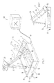
- the 3 shows the camera lens 1 and projector lens 3, which are arranged on a carrier plate 52.
- the carrier plate 52 is held on the bottom of the housing 12 via carrier plate fasteners 53 to 59.
- the camera lens 1 has a fixed lens part 62, while the projector lens has a fixed lens part 61.
- Rotary balancers 63 and 64 (around 350 °) are also provided for screw connections.
- An objective holder 86 connects to the rotary compensation 63.
- An arrow 87 indicates the adjustability of the objective 65.
- a projection optics 65 in a retrofocus arrangement, which initially reduces the image of a slide to the size of the CCD in the video camera.
- the slide shaft 69 carries a push button 70 for the slide ejection.
- a TV format aperture 71 is arranged between the slide shaft 69 and a lens with a convex configuration 72 and a concave configuration 73.
- the lenses 72, 73, a heat filter 74 and a planar sphere 75 serve to collimate the light from the lamp.
- the lamp 77 of the light source 16 is held by a lamp holder 78, which in turn is connected to the carrier plate 52 via a holding plate 79.
- the back of the lamp 77 has a concave mirror 80, which serves as a reflector.
- the holding plate 79 also carries a circuit board 81 with a microswitch for changing lamps and a switch-lamp changer 82.
- Reference number 83 denotes a lamp display.
- a CCD recording unit (camera) 66 which cooperates with a coupling for focal length adjustment 84, connects to the rotary compensator 64.
- the setting of the camera lenses 1 and 3 takes place synchronously by means of a motor transmission device 85 for IRIS / FOKUS / ZOOM. Cooling is carried out by a fan 60.
- Each videophone consists of a device and a picture monitor 38.38 '; the speech devices are not shown.
- the camera 14 of the first device is connected to the monitor 38 'of the second device and the camera 14' of the second device is connected to the monitor 38 of the first device.
- several videophones can be connected to each other at the same time.
- One of the main advantages of the illustrated video telephone is that not only the user, but also the object located on a projection surface 10 or an image projected there can be displayed on the monitor 38, 38 '. It is sufficient to pivot the mirror 22, 22 'about its pivot axis by an angle a, a'.
- the mirror 22 can be operated by means of a manipulator (not shown).
- the mirror 22, 22 'can preferably also be pivoted in such a way that it allows the image of the monitor 38, 38' to be displayed. If a flat-screen monitor is used, the thickness of which is regularly only a few cm, then this can be articulated on the housing 12 of the device, so that it can be pivoted from its ineffective (folded) working position into its effective (opened) working position. It may be appropriate to link the mirror 22, 22 'in the area of the upper edge of the monitor. If one takes into account that the mass of the components used can be very small, then it is possible to accommodate the videophone in a small case.
- the monitor can of course also be connected to a PC computer.
- the decisive factor in this variant of the invention is that the transmission of information is not limited to the reproduction of the user's image. With the same precision, everyone on the projection surface 10 or also other objects in the room are captured by the camera 14, 14 'and displayed in the monitor 38, 38'. If there is sufficient ambient light, the use of the light source or the projector can also be dispensed with.
- the mirror 22,22 ' can also be designed as a semi-transparent mirror and mounted directly in front of the monitor 38,38'.
- the device according to the invention can also have a PC connection on the video camera - in particular for red-green-blue color separation, so that the individual components can be processed separately, as a result of which the image quality can be increased.
- a 3-D adjustability of the mirrors also includes their height adjustment
Applications Claiming Priority (8)
| Application Number | Priority Date | Filing Date | Title |
|---|---|---|---|
| DE8812552 | 1988-10-05 | ||
| DE8812552U | 1988-10-05 | ||
| DE8901098U | 1989-02-01 | ||
| DE8901098U DE8901098U1 (fr) | 1988-10-05 | 1989-02-01 | |
| DE3909665 | 1989-03-23 | ||
| DE3909665A DE3909665A1 (de) | 1989-03-23 | 1989-03-23 | Geraet zur wiedergabe von bildern |
| CH2124/89A CH678576A5 (en) | 1988-10-05 | 1989-06-06 | Image converter providing video signal output |
| CH2124/89 | 1989-06-06 |
Publications (2)
| Publication Number | Publication Date |
|---|---|
| EP0362737A1 true EP0362737A1 (fr) | 1990-04-11 |
| EP0362737B1 EP0362737B1 (fr) | 1994-05-18 |
Family
ID=27428375
Family Applications (1)
| Application Number | Title | Priority Date | Filing Date |
|---|---|---|---|
| EP89118159A Expired - Lifetime EP0362737B1 (fr) | 1988-10-05 | 1989-09-30 | Appareil et procédé pour convertir des images en signaux vidéo |
Country Status (5)
| Country | Link |
|---|---|
| US (1) | US5027219A (fr) |
| EP (1) | EP0362737B1 (fr) |
| JP (1) | JPH02290388A (fr) |
| AT (1) | ATE105988T1 (fr) |
| DK (1) | DK485189A (fr) |
Cited By (3)
| Publication number | Priority date | Publication date | Assignee | Title |
|---|---|---|---|---|
| DE202008012676U1 (de) | 2008-09-24 | 2010-02-25 | Wolfvision Innovation Gmbh | Bildaufnahmegerät mit Aufnahmebereichs-Markierung |
| DE202008012677U1 (de) | 2008-09-24 | 2010-02-25 | Wolfvision Innovation Gmbh | Bildaufnahmegerät mit Aufnahmebereichs-Markierung |
| EP2903250A1 (fr) | 2014-01-31 | 2015-08-05 | WolfVision Innovation GmbH | Procédé de prise de vue avec émission de lumière de marquage adaptative et appareil de prise de vue correspondant |
Families Citing this family (19)
| Publication number | Priority date | Publication date | Assignee | Title |
|---|---|---|---|---|
| US5339173A (en) * | 1989-12-05 | 1994-08-16 | Canon Kabushiki Kaisha | Imaging apparatus having object plate and variably positionable image sensor |
| JP3062338B2 (ja) * | 1991-03-01 | 2000-07-10 | キヤノン株式会社 | 画像処理装置 |
| TW207573B (fr) * | 1991-12-30 | 1993-06-11 | Minnesota Mining & Mfg | |
| US5751355A (en) * | 1993-01-20 | 1998-05-12 | Elmo Company Limited | Camera presentation supporting system |
| JPH08186741A (ja) * | 1994-12-28 | 1996-07-16 | Nec Corp | 書画撮像装置 |
| US5947577A (en) * | 1994-12-28 | 1999-09-07 | Nec Corporation | Image pick-up device |
| US7224962B1 (en) | 1997-10-03 | 2007-05-29 | Karen Jeanne Kite | Remote operational screener |
| USD419170S (en) * | 1998-02-02 | 2000-01-18 | Nikon Corporation | Document camera |
| EP0987874B1 (fr) * | 1998-09-15 | 2003-08-13 | Josef Wolf | Appareil pour convertir des images en signaux électroniques |
| US7042486B2 (en) * | 1999-11-30 | 2006-05-09 | Eastman Kodak Company | Image capture and display device |
| US7420585B2 (en) * | 1999-11-30 | 2008-09-02 | Eastman Kodak Company | Image capture and display device |
| US6829371B1 (en) * | 2000-04-29 | 2004-12-07 | Cognex Corporation | Auto-setup of a video safety curtain system |
| US20020133889A1 (en) * | 2001-02-23 | 2002-09-26 | Molock Frank F. | Colorants for use in tinted contact lenses and methods for their production |
| US7050106B2 (en) * | 2001-11-21 | 2006-05-23 | Canon Kabushiki Kaisha | Image input device with rotatable image pickup unit |
| DE10210322A1 (de) * | 2002-03-08 | 2003-09-18 | Wolfvision Gmbh Goetzis | Auflagefläche eines Geräts zur optischen Aufnahme von Objekten |
| JP3764976B2 (ja) * | 2003-10-10 | 2006-04-12 | カシオ計算機株式会社 | 撮影機能付投射装置、及び投射画像撮影システム |
| US7209577B2 (en) | 2005-07-14 | 2007-04-24 | Logitech Europe S.A. | Facial feature-localized and global real-time video morphing |
| US20070230794A1 (en) * | 2006-04-04 | 2007-10-04 | Logitech Europe S.A. | Real-time automatic facial feature replacement |
| US20090244479A1 (en) * | 2008-03-31 | 2009-10-01 | Diana Zanini | Tinted silicone ophthalmic devices, processes and polymers used in the preparation of same |
Citations (3)
| Publication number | Priority date | Publication date | Assignee | Title |
|---|---|---|---|---|
| US3816654A (en) * | 1972-05-02 | 1974-06-11 | Stromberg Carlson Corp | Solid state camera tube embodying a fixed iris |
| GB1572151A (en) * | 1976-11-12 | 1980-07-23 | Kingsbury J | Prompting apparatus |
| WO1981000944A1 (fr) * | 1979-09-24 | 1981-04-02 | Datacopy Corp | Camera electronique utilisant un detecteur d'image a l'etat solide |
Family Cites Families (2)
| Publication number | Priority date | Publication date | Assignee | Title |
|---|---|---|---|---|
| US3833758A (en) * | 1972-07-07 | 1974-09-03 | Bell & Howell Co | Video information recording and display |
| JPS6271925A (ja) * | 1985-09-26 | 1987-04-02 | Canon Inc | 画像投影撮影装置 |
-
1989
- 1989-09-30 AT AT89118159T patent/ATE105988T1/de not_active IP Right Cessation
- 1989-09-30 EP EP89118159A patent/EP0362737B1/fr not_active Expired - Lifetime
- 1989-10-03 DK DK485189A patent/DK485189A/da not_active Application Discontinuation
- 1989-10-05 JP JP1258951A patent/JPH02290388A/ja active Granted
- 1989-10-05 US US07/417,579 patent/US5027219A/en not_active Expired - Lifetime
Patent Citations (3)
| Publication number | Priority date | Publication date | Assignee | Title |
|---|---|---|---|---|
| US3816654A (en) * | 1972-05-02 | 1974-06-11 | Stromberg Carlson Corp | Solid state camera tube embodying a fixed iris |
| GB1572151A (en) * | 1976-11-12 | 1980-07-23 | Kingsbury J | Prompting apparatus |
| WO1981000944A1 (fr) * | 1979-09-24 | 1981-04-02 | Datacopy Corp | Camera electronique utilisant un detecteur d'image a l'etat solide |
Cited By (3)
| Publication number | Priority date | Publication date | Assignee | Title |
|---|---|---|---|---|
| DE202008012676U1 (de) | 2008-09-24 | 2010-02-25 | Wolfvision Innovation Gmbh | Bildaufnahmegerät mit Aufnahmebereichs-Markierung |
| DE202008012677U1 (de) | 2008-09-24 | 2010-02-25 | Wolfvision Innovation Gmbh | Bildaufnahmegerät mit Aufnahmebereichs-Markierung |
| EP2903250A1 (fr) | 2014-01-31 | 2015-08-05 | WolfVision Innovation GmbH | Procédé de prise de vue avec émission de lumière de marquage adaptative et appareil de prise de vue correspondant |
Also Published As
| Publication number | Publication date |
|---|---|
| ATE105988T1 (de) | 1994-06-15 |
| US5027219A (en) | 1991-06-25 |
| DK485189A (da) | 1990-04-06 |
| JPH02290388A (ja) | 1990-11-30 |
| JPH0413916B2 (fr) | 1992-03-11 |
| EP0362737B1 (fr) | 1994-05-18 |
| DK485189D0 (da) | 1989-10-03 |
Similar Documents
| Publication | Publication Date | Title |
|---|---|---|
| EP0362737B1 (fr) | Appareil et procédé pour convertir des images en signaux vidéo | |
| DE19635666C1 (de) | Integriertes Mikroskop | |
| EP0553700B1 (fr) | Caméra vidéo pouvant être utilisée comme projecteur | |
| DE4244420C2 (de) | Tragbarer Flüssigkristallanzeige-Projektor | |
| DE2747615A1 (de) | Am kopf tragbare beleuchtungs- und fernsehaufnahmeeinrichtung | |
| DE4240583B4 (de) | Gerät zum Beobachten und Fotografieren eines Hornhaut-Endothels | |
| DE3020171A1 (de) | Suchervorrichtung fuer eine fernsehkamera | |
| AT522470A4 (de) | Fernoptisches Gerät mit Bilderfassungskanal | |
| EP1417925A1 (fr) | Appareil pour visualiser un oeil | |
| DE10045132B4 (de) | Verfahren zum automatischen Einstellen des Fokus bei einer verschlußlosen Digitalkamera | |
| DE10009571A1 (de) | Verfahren und Vorrichtung zum Justieren einer Kamera | |
| EP0987874B1 (fr) | Appareil pour convertir des images en signaux électroniques | |
| DE2611971A1 (de) | Optische vorrichtung zum uebertragen von licht oder zum betrachten eines bildes | |
| CH678576A5 (en) | Image converter providing video signal output | |
| WO2003058951A1 (fr) | Unite camera video | |
| DE4312654A1 (de) | Gegenlichtblende für Kameraobjektive, insbesondere von Video- und Filmkameras | |
| DE19653981B4 (de) | Präsentationssystem | |
| EP0595049A1 (fr) | Dispositif d'abonné pour vidéophone | |
| DE10243868A1 (de) | Objektivinformation-Anzeigevorrichtung | |
| DE4310677A1 (de) | Teilnehmergerät für Bildfernsprechen | |
| DE1814693C (de) | Spiegelreflex-Kamera mit rnikrophotometrischer Kontrolle | |
| DE4232866A1 (de) | Videokamera | |
| DE2216608C3 (de) | Vorrichtung zur selektiven optischen Übertragung eines Lichtbildes aus einer Vielzahl von Lichtbildquellen | |
| DE3421578C1 (de) | Vorrichtung zur Messung von mindestens im Meßbereich transparenten Vorlagen in Schwarz-Weiß oder Farbe | |
| DE102018122475A1 (de) | Einstellbares Streulichtblendenmodul für ein kinematografisches Kamerasystem |
Legal Events
| Date | Code | Title | Description |
|---|---|---|---|
| PUAI | Public reference made under article 153(3) epc to a published international application that has entered the european phase |
Free format text: ORIGINAL CODE: 0009012 |
|
| AK | Designated contracting states |
Kind code of ref document: A1 Designated state(s): AT BE CH DE ES FR GB IT LI NL SE |
|
| ITCL | It: translation for ep claims filed |
Representative=s name: JACOBACCI CASETTA & PERANI S.P.A. |
|
| GBC | Gb: translation of claims filed (gb section 78(7)/1977) | ||
| EL | Fr: translation of claims filed | ||
| 17P | Request for examination filed |
Effective date: 19901004 |
|
| TCNL | Nl: translation of patent claims filed | ||
| 17Q | First examination report despatched |
Effective date: 19921112 |
|
| GRAA | (expected) grant |
Free format text: ORIGINAL CODE: 0009210 |
|
| AK | Designated contracting states |
Kind code of ref document: B1 Designated state(s): AT BE CH DE ES FR GB IT LI NL SE |
|
| PG25 | Lapsed in a contracting state [announced via postgrant information from national office to epo] |
Ref country code: NL Effective date: 19940518 Ref country code: SE Free format text: THE PATENT HAS BEEN ANNULLED BY A DECISION OF A NATIONAL AUTHORITY Effective date: 19940518 Ref country code: BE Effective date: 19940518 |
|
| REF | Corresponds to: |
Ref document number: 105988 Country of ref document: AT Date of ref document: 19940615 Kind code of ref document: T |
|
| ITF | It: translation for a ep patent filed |
Owner name: JACOBACCI CASETTA & PERANI S.P.A. |
|
| GBT | Gb: translation of ep patent filed (gb section 77(6)(a)/1977) |
Effective date: 19940518 |
|
| REF | Corresponds to: |
Ref document number: 58907684 Country of ref document: DE Date of ref document: 19940623 |
|
| PG25 | Lapsed in a contracting state [announced via postgrant information from national office to epo] |
Ref country code: ES Free format text: LAPSE BECAUSE OF FAILURE TO SUBMIT A TRANSLATION OF THE DESCRIPTION OR TO PAY THE FEE WITHIN THE PRESCRIBED TIME-LIMIT Effective date: 19940829 |
|
| ET | Fr: translation filed | ||
| NLV1 | Nl: lapsed or annulled due to failure to fulfill the requirements of art. 29p and 29m of the patents act | ||
| PLBE | No opposition filed within time limit |
Free format text: ORIGINAL CODE: 0009261 |
|
| STAA | Information on the status of an ep patent application or granted ep patent |
Free format text: STATUS: NO OPPOSITION FILED WITHIN TIME LIMIT |
|
| 26N | No opposition filed | ||
| REG | Reference to a national code |
Ref country code: GB Ref legal event code: 732E |
|
| REG | Reference to a national code |
Ref country code: FR Ref legal event code: TP |
|
| REG | Reference to a national code |
Ref country code: CH Ref legal event code: NV Representative=s name: BUECHEL & PARTNER AG PATENTBUERO Ref country code: CH Ref legal event code: PUE Owner name: JOSEF WOLF AUDIO-VISUALS TRANSFER- JOSEF WOLF |
|
| REG | Reference to a national code |
Ref country code: GB Ref legal event code: IF02 |
|
| PGFP | Annual fee paid to national office [announced via postgrant information from national office to epo] |
Ref country code: CH Payment date: 20070925 Year of fee payment: 19 Ref country code: AT Payment date: 20070926 Year of fee payment: 19 |
|
| PGFP | Annual fee paid to national office [announced via postgrant information from national office to epo] |
Ref country code: FR Payment date: 20070920 Year of fee payment: 19 |
|
| PGFP | Annual fee paid to national office [announced via postgrant information from national office to epo] |
Ref country code: IT Payment date: 20080924 Year of fee payment: 20 |
|
| PGFP | Annual fee paid to national office [announced via postgrant information from national office to epo] |
Ref country code: GB Payment date: 20080924 Year of fee payment: 20 |
|
| PGFP | Annual fee paid to national office [announced via postgrant information from national office to epo] |
Ref country code: DE Payment date: 20080930 Year of fee payment: 20 |
|
| REG | Reference to a national code |
Ref country code: CH Ref legal event code: PL |
|
| REG | Reference to a national code |
Ref country code: FR Ref legal event code: ST Effective date: 20090529 |
|
| PG25 | Lapsed in a contracting state [announced via postgrant information from national office to epo] |
Ref country code: AT Free format text: LAPSE BECAUSE OF NON-PAYMENT OF DUE FEES Effective date: 20080930 |
|
| REG | Reference to a national code |
Ref country code: GB Ref legal event code: PE20 Expiry date: 20090929 |
|
| PG25 | Lapsed in a contracting state [announced via postgrant information from national office to epo] |
Ref country code: CH Free format text: LAPSE BECAUSE OF NON-PAYMENT OF DUE FEES Effective date: 20080930 Ref country code: LI Free format text: LAPSE BECAUSE OF NON-PAYMENT OF DUE FEES Effective date: 20080930 Ref country code: FR Free format text: LAPSE BECAUSE OF NON-PAYMENT OF DUE FEES Effective date: 20080930 |
|
| PG25 | Lapsed in a contracting state [announced via postgrant information from national office to epo] |
Ref country code: GB Free format text: LAPSE BECAUSE OF EXPIRATION OF PROTECTION Effective date: 20090929 |