EP0362480B1 - Méthode de comptage et d'encaissement de machines actionnées par pièces de monnaie et agencement de celles-ci pour la réalisation de la méthode - Google Patents
Méthode de comptage et d'encaissement de machines actionnées par pièces de monnaie et agencement de celles-ci pour la réalisation de la méthode Download PDFInfo
- Publication number
- EP0362480B1 EP0362480B1 EP89111815A EP89111815A EP0362480B1 EP 0362480 B1 EP0362480 B1 EP 0362480B1 EP 89111815 A EP89111815 A EP 89111815A EP 89111815 A EP89111815 A EP 89111815A EP 0362480 B1 EP0362480 B1 EP 0362480B1
- Authority
- EP
- European Patent Office
- Prior art keywords
- coin
- accordance
- coins
- machines
- fed
- Prior art date
- Legal status (The legal status is an assumption and is not a legal conclusion. Google has not performed a legal analysis and makes no representation as to the accuracy of the status listed.)
- Expired - Lifetime
Links
Images


Classifications
-
- G—PHYSICS
- G07—CHECKING-DEVICES
- G07F—COIN-FREED OR LIKE APPARATUS
- G07F17/00—Coin-freed apparatus for hiring articles; Coin-freed facilities or services
- G07F17/32—Coin-freed apparatus for hiring articles; Coin-freed facilities or services for games, toys, sports, or amusements
-
- G—PHYSICS
- G07—CHECKING-DEVICES
- G07F—COIN-FREED OR LIKE APPARATUS
- G07F5/00—Coin-actuated mechanisms; Interlocks
- G07F5/24—Coin-actuated mechanisms; Interlocks with change-giving
-
- G—PHYSICS
- G07—CHECKING-DEVICES
- G07F—COIN-FREED OR LIKE APPARATUS
- G07F7/00—Mechanisms actuated by objects other than coins to free or to actuate vending, hiring, coin or paper currency dispensing or refunding apparatus
- G07F7/04—Mechanisms actuated by objects other than coins to free or to actuate vending, hiring, coin or paper currency dispensing or refunding apparatus by paper currency
-
- G—PHYSICS
- G07—CHECKING-DEVICES
- G07F—COIN-FREED OR LIKE APPARATUS
- G07F9/00—Details other than those peculiar to special kinds or types of apparatus
- G07F9/08—Counting total of coins inserted
Definitions
- the invention relates to a method for collecting the coin money exceeding the minimum coin reserve in at least two coin-operated automatic machines, which is fed to a common coin receptacle via a common coin conveying device, and a counter which detects the amount of money generated is provided and a device with a banknote acceptor for carrying out the method.
- Vending machines in arcades, casinos and other vending machines have a typical circulation of money: Coins are required for the operation of the vending machines, but customers often do not have enough small change amounts, so that operators always have to keep considerable amounts of change in stock.
- the machine sales of the aforementioned companies are only in the form of coins, which leads to considerable amounts of coins and problems in terms of cash registers.
- the machines usually have to be opened so that the operation of the machine in question has to be interrupted.
- the checkout requires particularly trustworthy personnel.
- machines must always have a minimum coin reserve.
- Additional cash amounts can be removed from the machine.
- special devices are used, such as those described in DE-A-36 04 212. If a number of machines have to be billed and cashed at one installation site, this is perceived as being extremely cumbersome and labor-intensive, and there is always a risk of security and manipulation. It has proven to be beneficial and the wishes of the players shown in an accommodating manner to combine several coin-operated machines into a machine group, the machines then being able to be played simultaneously by one player. The amount of hard cash required for this must then be kept ready by the operator of the machine or a bill changer. This is perceived as uncomfortable by the players, since the machines that have been recorded must be left and third parties can observe the procurement of cash.
- GB-A-2 200 489 describes a method of the type mentioned at the outset, in which the coin money is fed to a common coin container via a common coin conveying device.
- the disadvantage here is that the coin movement is one-dimensional and irreversible, so that a regular refill of coin money is required.
- GB-A-2 112 985 it was known to introduce the amount of coins exceeding a specified minimum coin reserve in a coin collecting container as mixing money, the mixing money to be paid to an authorized person being counted and the amount being saved. With this device there is no separation of coin types but only the counting of the mixture of coins issued.
- the object of the invention is to improve the method of the type mentioned above and the device for carrying it out so that it is possible to either give coin money according to the value distribution Coin safe or to feed the money circulation system again.
- FIGS. 1 and 2 A particularly advantageous embodiment of compact arrangements 39, 40 of machines is shown in FIGS. 1 and 2, in which machine groups 41, 42 are shown.
- the machine group 41 consists of three machines 2, 3, 4, a changer 43 and three further machines 5 (FIG. 1).
- the machine group 42 consists of three machines 2, 3, 4 and a changer 43 (FIG. 2).
- the money changer 43 is used to change banknotes into coin money.
- the changer 43 and the machines 2, 3, 4, 5 are arranged in a cabinet-like device holder 44 and optically form a one-piece unit.
- the money changer 43 is expediently located in a safe-like security container.
- a coin safe 51 is provided in the substructure 45 of the device holder 44 under the money changer 43 (FIG. 1). However, it is also possible to arrange the coin safe 51 at another location on the substructure 45 (FIG. 2).
- the changer 43 and the machines 2, 3, 4, 5 are fastened to a holding wall 46 connected to the substructure 45. It is also possible to attach the money changer 43 and the machines 2, 3, 4, 5 to a shelf-like stand housing 97 individually. Such a stator housing 97 is indicated by broken lines in FIG. 2.
- Each stator housing 97 with a machine 2, 3, 4, 5 or money changer 43 then forms a machine module 90 of the respective arrangement of machines.
- the function of the arrangement 39 is like that of the arrangement 40 with the machine group 42, which is described in more detail below.
- the coin safe 51 is arranged offset from the changer 43.
- Each machine 2, 3, 4 has a coin slot (not shown in more detail) with a coin validator, device cash counter and coin stacking tubes with a coin payout device and a payout trough 50.
- the coin payout device is operated upon a corresponding game win. Coins thrown into the machines 2, 3, 4 are introduced into the machine 2, 3, 4 in coin boxes without being sorted.
- a sorting and counting device 47 which has two coin outlets 48, 49, is connected to the coin containers, preferably behind each machine 2, 3, 4.
- the coin outlet 48 is connected by means of a coin channel 52 to the coin inlet 56 of a hopper 54 arranged in the changer 43.
- the coin outlet 49 is connected to the coin safe 51 by means of a further coin channel 53.
- the coin channels 52, 53 which can also be configured as coin tubes, have the function of coin conveying devices 17.
- a coin container 55 is assigned to the hopper 54 on the coin output side, the coin dispensing devices of which can be controlled by the bill changing device 16.
- the bill exchange facility 16 has a bill reader 62, which can be designed by appropriate programming for reading various banknotes.
- the banknote reader 62 of the banknote changing device 16 can carry out a perfect banknote check by means of a suitable spectral analysis, so that there is a high level of security against counterfeit products.
- the bill reader 62 is followed by a device, not shown, for preventing bill withdrawal. It is expedient to design the bill collecting container 31 as a box-like container which can be removed from the changer 43. Furthermore, it is possible to connect a banknote stacker to the banknote collecting container 31, so that the banknotes are introduced into the banknote collecting container 31 packed in bundles depending on their value.
- the coin stacking tubes of machines 2, 3, 4, 5 are filled with the required amount of coin money.
- the amount of the coins issued for winnings is recorded by the payout counter of the coin dispenser of the respective machine 2, 3, 4, 5.
- additional coin money is sorted by means of the sorting and counting devices 47 to such an extent that a preferred type of coin money is fed to the changer 43 via the respective coin channel 52.
- the preferred coin type will be the one that embodies the highest value as coin money.
- the further unsorted coin money accumulating in the coin collecting container 58 (FIG. 3) of the machines 2, 3, 4, 5 remains unsorted and is supplied to the coin money safe 51 via the coin channel 53.
- the hopper 54 of the money changer 43 is automatically filled up by playing on the machines 2, 3, 4, 5.
- the bill changer 43 can be designed in such a way that, if necessary, the hopper 54 can also be filled up manually from the outside without the coin collecting space of the hopper 54 having to be opened.
- FIG. 3 schematically shows a further embodiment of the machines 2, 3, 4, 5 of the machine groups 41, 42, by means of which the handling of coin money is further simplified since no coin stacking tubes are required.
- Both the coin money to be inserted into the machines 2, 3, 4, 5 during commissioning and the coin money introduced during the game operation via the coin slot 6 goes unsorted into a coin collecting container 58 of each machine 2, 3, 4, 5 a coin outlet 8 of the payment device with a payment trough 50.
- the coin outlet 8 is connected to the coin collecting container 58 in the machine 2, 3, 4, 5.
- the coin dispenser 61 is also connected to the sorting and counting device 47, as shown schematically in FIG. 3.
- the sorting and counting device 47 By means of the sorting and counting device 47, the unsorted coin money from the coin collecting container 58 is fed to the coin outlet 8, the payout counter 63 being used by the coin validator 59 to pay the amounts of issued coins added up.
- the coin dispensing is interrupted. It is possible to set the coin dispenser 61 so that certain types of coins are preferably dispensed. This makes it possible to relieve the coin collecting container 58 of low-value coins. On the other hand, the player receives a large number of low-value coins when he wins, which will often cause him to get rid of these coins by continuing to play.
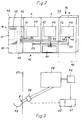
- FIG. 4 schematically shows a further embodiment of an arrangement of machines 2, 3, 4, 5 with a money changer 43.
- a coin store 33 is arranged, which has an opening flap 34 on the bottom.
- the output of the coin buffer 33 is assigned to a coin conveyor 17.
- the end section 18 of the coin conveyor 17 on the conveyor side is guided up to the coin entrance 56 of a hopper 54 of a changer 43.
- the coin dispenser of the hopper 54 can be controlled by the bill changer device of the changer 43, which is not shown in detail.
- coin outlets 49 can also be provided on the machines 2, 3, 4, 5 for discharging unsorted coin money.
- a coin buffer 33 with an opening flap 34 on the bottom it is possible to assign a coin buffer 33 with an opening flap 34 on the bottom to each coin outlet 49.
- the unsorted coin money arrives from the intermediate coin store 33 on a coin conveying device 17 whose end section 18 on the conveying side is assigned to a central coin receiving container 60.
- the coin receptacle 60 can be designed as a further coin safe.
- a hopper 21 is arranged in the coin receiving container 60 and has a coin validator 22 on the coin exit side.
- the coin validator 22 is connected to a coin diverter 23 in the coin conveying direction.
- Coins of a preferred type of coin are fed to the coin entrance 56 of the hopper 54 in the changer 43. Remaining unsorted coins go into the coin safe 51.
- a coin conveyor 17 is provided between the coin diverter 23 and the coin entrance 56 for the transport of the corresponding coins.
- a coin conveying device 17 is also arranged between the coin separator 23 and the coin safe 51.
- Coin channels can be used as coin conveying device 17 when the coins can reach their destination by gravity due to the gradient of the coin channels. It is also possible, as an alternative, to feed unsorted coin money to the machines 2, 3, 4, 5 again via a further coin branch 24 instead of the coin money safe 51, as is indicated in FIG. 5 by dashed lines.
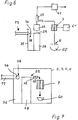
- a hopper 28 can be arranged in each machine 2, 3, 4, 5, and a coin validator 22 with a coin switch 23 is formed at the coin outlet 29 thereof.
- the coin diverter 23 is connected to the coin dispenser 61 assigned to the coin outlet 8 of the payment trough 50 and to a sorting and counting device 47.
- the hoppers 28 are each arranged in a coin space 35, on the upper portion of which a coin inlet opening 36 is provided.
- the coin inlet opening 36 is connected to a coin conveyor 17.
- the coin conveying device 17 is connected on the coin entrance side to the coin diverter 23 assigned to the hopper 21 in the coin receiving container 60.
- the coin delivery device 61 is connected to coin stacking tubes 7, from which coin money passes through the coin outlet 8 for payment into the payment trough 50.
- FIG. 7 schematically shows a machine 2, 3, 4, 5, which also has a hopper 28 in a coin room 35.
- the coin outlet 29 of the hopper 28 is connected as in FIG. 6 via a coin validator 22 and a coin switch 23 to coin stacking tubes 7, which via the coin switch 23 to the required coins can be filled. Payouts of winnings are deducted from the coin stacking tubes 7.
- the coin space 35 also has a coin inlet opening 36 which can be closed by means of a flap 38. The position of the flap 38 is controlled by means of a coin dispenser 61 which also acts on the hopper 21 in the central coin receptacle 60.
- the hopper 21 in the coin receptacle 60 and the position of the flap 38 are controlled as a function of control pulses from the profit-determining device of the respective machine 2, 3, 4, 5.
- the mentioned coin conveyors 17 can be configured as coin tubes, belt conveyors, chain conveyors, pocket conveyors, pneumatic conveyors or magnetic conveyors. These conveyors allow the coins to be conveyed to be transported horizontally, upwards and downwards and possibly vertically. This makes it possible to provide larger arrangements of machines 2, 3, 4, 5 even in a geometrically offset position.
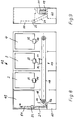
- FIGS. 8 and 9 show a machine group 42 with a money changer 43, in which the coin conveying device 17 is designed as a chain conveyor 19 for serial money quantity processing.
- a coin buffer 33 with an opening flap 34 is provided on each machine 2, 3, 4.
- the chain conveyor 19 can be reversed with respect to the feed direction and has a coin receiving tray 11.
- Each coin buffer 33 of the machines 2, 3, 4 is emptied into the coin receptacle 11. This is then moved by the chain conveyor 19 to the changer 43 and emptied through a coin entrance 56 into a central coin receptacle 60.
- a hopper 21 promotes the amount of coins by a coin validator 22.
- the amount of coin money received by the respective machine 2, 3, 4 is registered and the coin money is fed to further hoppers 54 via coin branches.
- the coin money is again divided in terms of value and fed back to the money circulation system or to a coin safe 51.
- This arrangement makes it possible to connect a large number of machines 2, 3, 4, which are also spatially distant from one another, to a money changer, the coin money proceeds from each machine 2, 3, 4 being able to be recorded individually.
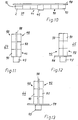
- FIG. 10 shows a schematic top view of an arrangement 39, which consists of automatic modules 90 and a central money changer 43.
- the arrangement 39 is connected to a partition 98 as a screen.
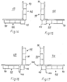
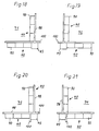
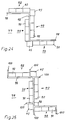
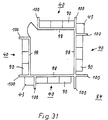
- 11 to 31 further arrangements 64 to 84 of machine groups 41, 42 are shown.
- partition walls 98 and, if applicable, transverse partition walls 99 and wall projections 100 formed on the partition walls 98 the most varied of floor plan configurations can be created for the arrangement of groups of machines 41, 42.
- the arrangements can only consist of arrangements 40, each with a machine group 42, or also additionally of an arrangement 39, with a machine group 41.
- Each of these arrangements 64 to 84 ensures that a player can operate his machine group unobserved by third parties and can also use the money changer 43 unobserved.
Landscapes
- Physics & Mathematics (AREA)
- General Physics & Mathematics (AREA)
- Control Of Vending Devices And Auxiliary Devices For Vending Devices (AREA)
- Testing Of Coins (AREA)
- Pinball Game Machines (AREA)
- Coin-Freed Apparatuses For Hiring Articles (AREA)
- Devices For Checking Fares Or Tickets At Control Points (AREA)
Claims (23)
- Procédé de collecte de pièces de monnaies débordant de la réserve minimale de pièces dans au moins deux automates actionnés par des pièces de monnaie, en les envoyant, au moyen d'un dispositif commun de transport de pièces de monnaie, vers un récipient commun des pièces de monnaie, étant entendu qu'il est prévu un compteur déterminant la quantité d'argent qui arrive, caractérisé en ce que, pour réaliser un système de rotation de l'argent, on trie, parmi les pièces de monnaie envoyée au dispositif de transport de pièces de monnaie (17), une sorte de pièces préférée et on l'envoie, au moyen d'un autre dispositif de transport de pièces, à un changeur de monnaie (43) et que les pièces de monnaie en excès restantes, sont envoyées, non triées, à un coffre (51) pour ces pièces de monnaie, réalisé sous la forme d'un récipient de collecte commun des pièces de monnaie (60), étant entendu que, lorsqu'a été atteint un niveau de consigne pour le remplissage du changeur de monnaie (43) par la sorte de monnaie préférée, ou par les sortes de monnaie préférée, les autres pièces de mannaie tombant dans les automates (2, 3, 4, 5) et appartenant à la sorte de pièces de monnaie préférée, sont envoyées au coffre (51) pour pièces de monnaie.
- Procédé suivant la revendication 1, caractérisé en ce que les pièces de monnaie de la sorte de pièces de monnaie préférée, ou des sortes de pièces de monnaie préférées se trouvant dans le changeur de monnaie (43), est envoyée, ou sont envoyées, vers une ou plusieurs trémies (54), d'où les pièces de monnaie sont envoyées à un auget de paiement (50), conformément à la valeur d change du billet d banque.
- Procédé suivant la revendication 1, caractérisé en ce que le montant des pièces de monnaie sortant de chacun des automates (2, 3, 4, 5) est additionné avec un compteur de caisse.
- Dispositif de collecte de pièces de monnaies dépassant la réserve minimale de pièces dans au moins deux automates actionnés par des pièces de monnaie, en les envoyant, par l'intermédiaire d'un dispositif commun de triage de pièces de monnaie, de chaque automate (3, 4, 5), vers un dispositif de transport de pièces de monnaies (17), qui est relié à une entrée commune de sécurité d'un récipient central de collecte des pièces de monnaie, et comportant au moins un dispositif acceptant les billets de banque, caractérisé en ce que, pour réaliser un système de rotation de l'argent, le dispositif acceptant les billets de banque est disposé dans un changeur de monnaie (43) et le récipient de collecte central des pièces de monnaie (60) est réalisé sous la forme d'un coffre pour pièces de monnaies (51), en ce que chaque dispositif de tri de pièces de monnaies est réalisé sous la forme d'un dispositif de tri et de comptage (47) comportant deux sorties de pièces (48, 49), dont la sortie correspondante (48) est réalisée pour une sorte définie de pièces de monnaie et est reliée à l'entrée de pièces (56) d'une trémie (54), qui est disposée dans le changeur de monnaie (43), et dont les dispositifs distributeurs de pièces peuvent être commandés par un dispositif de change de billets de banque (16), et l'autre sortie (49), destinée à délivrer des pièces de monnaie non triées, est reliée au coffre (51) pour pièces de monnaie.
- Dispositif suivant la revendication 4, caractérisé en ce que les dispositifs de tri et de comptage (47) sont disposés dans les automates (2, 3, 4, 5).
- Dispositif suivant la revendication 4, caractérisé en ce que les dispositifs de tri et de comptage (47) sont disposés en dehors des automates (2, 3, 4, 5), dans un boîtier support (97) ou un support d'appareils formant armoire (44).
- Dispositif suivant la revendication 4, caractérisé en ce que le dispositif de change de billets de banque (16) présente un compteur d'entrée des billets de banque et en ce que le récipient de collecte des billets de banque (31) est disposé dans une zone fermée conforme à la technique de sécurité.
- Dispositif suivant la revendication 4, caractérisé en ce que les sorties de pièces (48) pour délivrer une sorte bien définie de pièce de monnaie sont disposées au-dessus d'un dispositif de transport de pièces de monnaies (17), dont la partie d'extrémité (18) située du côté du transporteur est associée à l'entrée de pièces (56) de la trémie (54) disposée dans le changeur de monnaie (43).
- Dispositif suivant la revendication 4, caractérisé en ce que seulement des sorties de pièces (49) pour délivrer des pièces de monnaie non triées sont disposées au-dessus d'un dispositif de transport de pièces de monnaies (17), dont la partie d'extrémité (18), située du côté du transporteur, est associée à un récipient de collecte des pièces de monnaie (60), dans lequel est disposée une trémie (21) comportant un contrôleur de pièces (22) situé du côté de la sortie des pièces, au moyen duquel, par l'intermédiaire d'un aiguillage à pièces (23), on peut adresser des pièces, d'au moins une sorte préférée, à l'entrée de pièces (56) d'au moins une trémie (54) située dans le changeur de monnaie (43) et les pièces de monnaie non triées restantes peuvent être envoyées à un coffre (51) pour pièces de monnaie.
- Dispositif suivant la revendication 9, caractérisé en ce qu'entre l'aiguillage à pièces (23) et l'entrée de pièces (56), est placé un dispositif de transport de pièces de monnaies (17).
- Dispositif suivant la revendication 9, caractérisé en ce qu'entre l'aiguillage à pièces (23) et le coffre (51) pour pièces de monnaie, est placé un dispositif de transport de pièces de monnaies (17).
- Dispositif suivant la revendication 4, caractérisé en ce qu'aux sorties de pièces (48, 49) du dispositif de tri et de comptage (47), sont disposés des réservoirs intermédiaires de pièces (33), dont les clapets d'ouverture côté fond (34) sont associés aux dispositifs de transport de pièces de monnaies (17).
- Dispositif suivant la revendication 4, dans le cas duquel, dans chacun des automates (2, 3, 4, 5), est disposé une trémie (28), à la sortie de pièces (29) duquel est réalisé un contrôleur de monnaie (27) comportant un aiguillage à pièces (23), qui est relié au dispositif de distribution de pièces de monnaie (61), associé à la sortie de pièces (8) de l'auget de paiement (50), et qui est relié au dispositif de tri des pièces de monnaie des automates (2, 3, 4, 5), caractérisé en ce que les trémies (28) sont chacune disposées dans une enceinte pour pièces de monnaie (35), à la partie supérieure de laquelle est réalisée une ouverture d'introduction des pièces (36), qui est raccordée à un dispositif de transport de pièces de monnaies (17).
- Dispositif suivant la revendication 13, caractérisé en ce que le dispositif de transport de pièces de monnaies (17) est raccordé, du côté entrée des pièces, avec l'aiguillage à pièces (23) associé à la trémie (21) dans le récipient de collecte des pièces de monnaie (60).
- Dispositif suivant la revendication 13, caractérisé en ce que le dispositif de transport de pièces de monnaies (17) est raccordé, du côté sortie des pièces, à la sortie de pièces (8) de l'auget de paiement (50) par l'intermédiaire d'une ouverture d'introduction des pièces (36) réalisée sur les automates (2, 3, 4, 5), étant entendu que l'ouverture d'introduction des pièces (36) peut être fermée par un clapet (38) dont la position peut être commandée, en même temps que la trémie (21) disposée dans le récipient de collecte des pièces de monnaie (60), par le dispositif de distribution de pièces de monnaie (61) en fonction d'impulsions de commande du dispositif de chaque automate (2, 3, 4, 5), déterminant les gagnants.
- Dispositif suivant la revendication 4, caractérisé en ce que le dispositif de transport de pièces de monnaies (17), associé, directement ou indirectement, aux sorties de pièces (48, 49), est réalisé sous la forme de canaux (52, 53) pour pièces, de tubes pour pièces, de convoyeurs à bande, de convoyeurs à chaîne, de convoyeurs à godets, de transporteurs pneumatiques ou magnétiques.
- Dispositif suivant la revendication 12, caractérisé en ce que le dispositif de transport de pièces de monnaies (17) reliant les réservoirs intermédiaires de pièces (33) au récipient de collecte des pièces de monnaie (60) est réalisé sous la forme d'un transporteur à chaîne (19), dont le sens de marche est inversable, et comportant au moins une cuvette de réception de pièces de monnaie.
- Dispositif suivant la revendication 4, caractérisé en ce que les automates (2, 3, 4, 5) actionnés par pièces de monnaie sont intégrés dans une armoire réalisée sous la forme d'un coffre, ou sont suspendus ou placés au-dessus d'une armoire réalisée sous la forme d'un coffre.
- Dispositif suivant la revendication 4, caractérisé en ce que les automates (2, 3, 4, 5), le changeur de monnaie (43), les canaux à pièces (52, 53) associés aux sorties de pièces (48, 49) et le coffre (51) pour pièces de monnaie sont disposés dans un support d'appareils (44) en une seule pièce, formant armoire.
- Dispositif suivant la revendication 4, caractérisé en ce que chaque automate (2, 3, 4, 5) et le changeur de monnaie (43), avec leurs canaux à pièces associés (52, 53), sont disposés chacun sur un boîtier support (97) formant armoire.
- Dispositif suivant la revendication 4, caractérisé en ce qu'en avant de la sortie de pièces (8) de chacun des automates (2, 3, 4, 5) et du changeur de monnaie (43), est disposé un contrôleur de pièces de monnaie (59), relié à un compteur de paiement (63) d'un dispositif de distribution de pièces de monnaie (61), compteur qui est disposé dans les automates (2, 3, 4, 5).
- Dispositif suivant la revendication 21, caractérisé en ce que le dispositif de distribution de pièces de monnaie (61) peut être réglé en fonction des sortes de pièces de monnaie à délivrer, et est relié au dispositif de tri et de comptage (47).
- Dispositif suivant la revendication 4, caractérisé en ce que, sur chacune des parois verticales (98) reliées entre elles en formant un angle, qui présentent, le cas échéant, des parois verticales transversales (99) et des saillies (100) dans la paroi, des automates sont disposés en (39) et en (40).
Applications Claiming Priority (4)
| Application Number | Priority Date | Filing Date | Title |
|---|---|---|---|
| DE3834019 | 1988-10-06 | ||
| DE19883834019 DE3834019A1 (de) | 1987-04-13 | 1988-10-06 | Verfahren zur abrechnung und kassierung von muenzbetaetigten automaten und vorrichtung zur durchfuehrung des verfahrens |
| DE8902145U DE8902145U1 (de) | 1988-10-06 | 1989-02-23 | Vorrichtung von münzbetätigten Automaten mit einer Vorrichtung zu deren Abrechnung und Kassierung |
| DE8902145U | 1989-02-23 |
Publications (3)
| Publication Number | Publication Date |
|---|---|
| EP0362480A2 EP0362480A2 (fr) | 1990-04-11 |
| EP0362480A3 EP0362480A3 (fr) | 1991-05-08 |
| EP0362480B1 true EP0362480B1 (fr) | 1994-09-14 |
Family
ID=25872926
Family Applications (1)
| Application Number | Title | Priority Date | Filing Date |
|---|---|---|---|
| EP89111815A Expired - Lifetime EP0362480B1 (fr) | 1988-10-06 | 1989-06-29 | Méthode de comptage et d'encaissement de machines actionnées par pièces de monnaie et agencement de celles-ci pour la réalisation de la méthode |
Country Status (3)
| Country | Link |
|---|---|
| EP (1) | EP0362480B1 (fr) |
| AT (1) | ATE111619T1 (fr) |
| DE (1) | DE58908356D1 (fr) |
Families Citing this family (2)
| Publication number | Priority date | Publication date | Assignee | Title |
|---|---|---|---|---|
| JP2849696B2 (ja) * | 1993-02-17 | 1999-01-20 | 株式会社エース電研 | 遊技機島の両替機取付装置 |
| AT405339B (de) * | 1994-07-15 | 1999-07-26 | Novo Invest Casino Dev Ag | Vorrichtung mit zumindest einem spielgerät sowie münzeinheit |
Citations (1)
| Publication number | Priority date | Publication date | Assignee | Title |
|---|---|---|---|---|
| GB2112985A (en) * | 1981-11-10 | 1983-07-27 | Coin Controls | Money operated machine |
Family Cites Families (4)
| Publication number | Priority date | Publication date | Assignee | Title |
|---|---|---|---|---|
| CH601870A5 (fr) * | 1976-07-19 | 1978-07-14 | Autelca Ag | |
| DE3604212A1 (de) * | 1986-02-11 | 1987-08-20 | Bergmann & Co Th | Vorrichtung zur geldentnahme aus geldspielgeraeten |
| GB2200489A (en) * | 1987-01-28 | 1988-08-03 | Mecca Leisure Limited | Token collection |
| ES2049224T3 (es) * | 1987-04-13 | 1994-04-16 | Bergmann & Co Th | Procedimiento de liquidacion y recaudacion para maquinas automaticas que funcionan con monedas e instalacion para realizacion del procedimiento. |
-
1989
- 1989-06-29 DE DE58908356T patent/DE58908356D1/de not_active Expired - Fee Related
- 1989-06-29 AT AT89111815T patent/ATE111619T1/de not_active IP Right Cessation
- 1989-06-29 EP EP89111815A patent/EP0362480B1/fr not_active Expired - Lifetime
Patent Citations (1)
| Publication number | Priority date | Publication date | Assignee | Title |
|---|---|---|---|---|
| GB2112985A (en) * | 1981-11-10 | 1983-07-27 | Coin Controls | Money operated machine |
Also Published As
| Publication number | Publication date |
|---|---|
| EP0362480A3 (fr) | 1991-05-08 |
| ATE111619T1 (de) | 1994-09-15 |
| EP0362480A2 (fr) | 1990-04-11 |
| DE58908356D1 (de) | 1994-10-20 |
Similar Documents
| Publication | Publication Date | Title |
|---|---|---|
| DE19739459C2 (de) | Geldwechselvorrichtung | |
| DE69500822T2 (de) | Spielautomat mit dem gesetzlich erforderlichen, mechanischen Zählern und einer elektronischen Guthabeneinführvorrichtung | |
| DE3744813C2 (de) | Maschine zur Annahme und Ausgabe von Banknoten | |
| EP1653416A2 (fr) | Procédé pour commander la distribution de pieces de monnaie dans une machine à sous | |
| DE4042702B4 (de) | Verfahren zum Betreiben geldbetätigter Unterhaltungsautomaten | |
| DE19701943B4 (de) | Münzverarbeitungseinrichtung für einen Verkaufsautomaten | |
| DE3834020A1 (de) | Muenzbetaetigtes geldspielgeraet und verfahren zur sortierung und abgabe des in diesem befindlichen muenzgeldes sowie anordnung zur durchfuehrung des verfahrens | |
| DE3834019A1 (de) | Verfahren zur abrechnung und kassierung von muenzbetaetigten automaten und vorrichtung zur durchfuehrung des verfahrens | |
| EP0362480B1 (fr) | Méthode de comptage et d'encaissement de machines actionnées par pièces de monnaie et agencement de celles-ci pour la réalisation de la méthode | |
| DE3227438A1 (de) | Muenzspielgeraet | |
| AT405339B (de) | Vorrichtung mit zumindest einem spielgerät sowie münzeinheit | |
| EP1423828A2 (fr) | Dispositif de reception d'argent | |
| DE4125245C2 (de) | Geldwechseleinrichtung | |
| EP0287049B1 (fr) | Procédé de liquidation et d'encaissement de machines automatiques actionnées par pièces de monnaie et installation pour la réalisation de ce procédé | |
| DE60027583T2 (de) | Bargeldverarbeitungsvorrichtung | |
| DE3834018C2 (de) | Verfahren zur Ausgabe einer wahlweise aus Münzen und/oder Geldscheinen bestehenden Geldmenge in der Währung eines auswählbaren Landes aus einem Geldwechselautomaten und Geldwechselautomat zur Durchführung des Verfahrens | |
| DE3902097A1 (de) | Einrichtung zum geldwechseln in einer spielstaette mit muenzbetaetigten unterhaltungsgeraeten | |
| DE4212760C1 (en) | Change dispensing mechanism for coin-operated amusement machine - allows inserted playing tokens to be exchanged for corresponding amount of change under control of key switch | |
| DE3304125A1 (de) | Geldbetaetigtes geraet | |
| DE4003702C2 (fr) | ||
| DE8812583U1 (de) | Vorrichtung zur Abrechnung und Kassierung von münzbetätigten Automaten | |
| EP1014315B1 (fr) | Changeur de monnaie d'un automate à pièces de monnaie pour la réception de monnaie nationale et de l'Euro | |
| DE8902145U1 (de) | Vorrichtung von münzbetätigten Automaten mit einer Vorrichtung zu deren Abrechnung und Kassierung | |
| DE19726458B4 (de) | Münzbetätigtes Spielgerät in kompakter Bauform und Verfahren zur Ausgabe von Geldbeträgen | |
| DE102004054002A1 (de) | Verfahren zur Steuerung eines Münzauszahlvorganges an einem münzbetätigten Unterhaltungsautomaten |
Legal Events
| Date | Code | Title | Description |
|---|---|---|---|
| PUAI | Public reference made under article 153(3) epc to a published international application that has entered the european phase |
Free format text: ORIGINAL CODE: 0009012 |
|
| AK | Designated contracting states |
Kind code of ref document: A2 Designated state(s): AT BE CH DE ES FR GB GR IT LI LU NL SE |
|
| PUAL | Search report despatched |
Free format text: ORIGINAL CODE: 0009013 |
|
| AK | Designated contracting states |
Kind code of ref document: A3 Designated state(s): AT BE CH DE ES FR GB GR IT LI LU NL SE |
|
| 17P | Request for examination filed |
Effective date: 19911030 |
|
| 17Q | First examination report despatched |
Effective date: 19930301 |
|
| GRAA | (expected) grant |
Free format text: ORIGINAL CODE: 0009210 |
|
| AK | Designated contracting states |
Kind code of ref document: B1 Designated state(s): AT BE CH DE ES FR GB GR IT LI LU NL SE |
|
| PG25 | Lapsed in a contracting state [announced via postgrant information from national office to epo] |
Ref country code: ES Free format text: THE PATENT HAS BEEN ANNULLED BY A DECISION OF A NATIONAL AUTHORITY Effective date: 19940914 Ref country code: GR Free format text: LAPSE BECAUSE OF FAILURE TO SUBMIT A TRANSLATION OF THE DESCRIPTION OR TO PAY THE FEE WITHIN THE PRESCRIBED TIME-LIMIT Effective date: 19940914 Ref country code: NL Effective date: 19940914 Ref country code: FR Effective date: 19940914 Ref country code: BE Effective date: 19940914 Ref country code: GB Effective date: 19940914 Ref country code: IT Free format text: LAPSE BECAUSE OF FAILURE TO SUBMIT A TRANSLATION OF THE DESCRIPTION OR TO PAY THE FEE WITHIN THE PRESCRIBED TIME-LIMIT;WARNING: LAPSES OF ITALIAN PATENTS WITH EFFECTIVE DATE BEFORE 2007 MAY HAVE OCCURRED AT ANY TIME BEFORE 2007. THE CORRECT EFFECTIVE DATE MAY BE DIFFERENT FROM THE ONE RECORDED. Effective date: 19940914 |
|
| REF | Corresponds to: |
Ref document number: 111619 Country of ref document: AT Date of ref document: 19940915 Kind code of ref document: T |
|
| REF | Corresponds to: |
Ref document number: 58908356 Country of ref document: DE Date of ref document: 19941020 |
|
| PG25 | Lapsed in a contracting state [announced via postgrant information from national office to epo] |
Ref country code: SE Effective date: 19941214 |
|
| EN | Fr: translation not filed | ||
| NLV1 | Nl: lapsed or annulled due to failure to fulfill the requirements of art. 29p and 29m of the patents act | ||
| GBV | Gb: ep patent (uk) treated as always having been void in accordance with gb section 77(7)/1977 [no translation filed] |
Effective date: 19940914 |
|
| PG25 | Lapsed in a contracting state [announced via postgrant information from national office to epo] |
Ref country code: AT Effective date: 19950629 |
|
| PG25 | Lapsed in a contracting state [announced via postgrant information from national office to epo] |
Ref country code: LI Effective date: 19950630 Ref country code: LU Free format text: LAPSE BECAUSE OF NON-PAYMENT OF DUE FEES Effective date: 19950630 Ref country code: CH Effective date: 19950630 |
|
| PLBE | No opposition filed within time limit |
Free format text: ORIGINAL CODE: 0009261 |
|
| STAA | Information on the status of an ep patent application or granted ep patent |
Free format text: STATUS: NO OPPOSITION FILED WITHIN TIME LIMIT |
|
| 26N | No opposition filed | ||
| REG | Reference to a national code |
Ref country code: CH Ref legal event code: PL |
|
| PGFP | Annual fee paid to national office [announced via postgrant information from national office to epo] |
Ref country code: DE Payment date: 19980729 Year of fee payment: 10 |
|
| PG25 | Lapsed in a contracting state [announced via postgrant information from national office to epo] |
Ref country code: DE Free format text: LAPSE BECAUSE OF NON-PAYMENT OF DUE FEES Effective date: 20000503 |