EP0361708A2 - Regler für regeneratives Bremssystem - Google Patents
Regler für regeneratives Bremssystem Download PDFInfo
- Publication number
- EP0361708A2 EP0361708A2 EP89309040A EP89309040A EP0361708A2 EP 0361708 A2 EP0361708 A2 EP 0361708A2 EP 89309040 A EP89309040 A EP 89309040A EP 89309040 A EP89309040 A EP 89309040A EP 0361708 A2 EP0361708 A2 EP 0361708A2
- Authority
- EP
- European Patent Office
- Prior art keywords
- brake
- regenerative
- friction
- braking
- torque
- Prior art date
- Legal status (The legal status is an assumption and is not a legal conclusion. Google has not performed a legal analysis and makes no representation as to the accuracy of the status listed.)
- Granted
Links
Images


Classifications
-
- B—PERFORMING OPERATIONS; TRANSPORTING
- B60—VEHICLES IN GENERAL
- B60W—CONJOINT CONTROL OF VEHICLE SUB-UNITS OF DIFFERENT TYPE OR DIFFERENT FUNCTION; CONTROL SYSTEMS SPECIALLY ADAPTED FOR HYBRID VEHICLES; ROAD VEHICLE DRIVE CONTROL SYSTEMS FOR PURPOSES NOT RELATED TO THE CONTROL OF A PARTICULAR SUB-UNIT
- B60W30/00—Purposes of road vehicle drive control systems not related to the control of a particular sub-unit, e.g. of systems using conjoint control of vehicle sub-units, or advanced driver assistance systems for ensuring comfort, stability and safety or drive control systems for propelling or retarding the vehicle
- B60W30/18—Propelling the vehicle
- B60W30/18009—Propelling the vehicle related to particular drive situations
- B60W30/18109—Braking
- B60W30/18127—Regenerative braking
-
- B—PERFORMING OPERATIONS; TRANSPORTING
- B60—VEHICLES IN GENERAL
- B60L—PROPULSION OF ELECTRICALLY-PROPELLED VEHICLES; SUPPLYING ELECTRIC POWER FOR AUXILIARY EQUIPMENT OF ELECTRICALLY-PROPELLED VEHICLES; ELECTRODYNAMIC BRAKE SYSTEMS FOR VEHICLES IN GENERAL; MAGNETIC SUSPENSION OR LEVITATION FOR VEHICLES; MONITORING OPERATING VARIABLES OF ELECTRICALLY-PROPELLED VEHICLES; ELECTRIC SAFETY DEVICES FOR ELECTRICALLY-PROPELLED VEHICLES
- B60L15/00—Methods, circuits, or devices for controlling the traction-motor speed of electrically-propelled vehicles
- B60L15/20—Methods, circuits, or devices for controlling the traction-motor speed of electrically-propelled vehicles for control of the vehicle or its driving motor to achieve a desired performance, e.g. speed, torque, programmed variation of speed
- B60L15/2009—Methods, circuits, or devices for controlling the traction-motor speed of electrically-propelled vehicles for control of the vehicle or its driving motor to achieve a desired performance, e.g. speed, torque, programmed variation of speed for braking
-
- B—PERFORMING OPERATIONS; TRANSPORTING
- B60—VEHICLES IN GENERAL
- B60L—PROPULSION OF ELECTRICALLY-PROPELLED VEHICLES; SUPPLYING ELECTRIC POWER FOR AUXILIARY EQUIPMENT OF ELECTRICALLY-PROPELLED VEHICLES; ELECTRODYNAMIC BRAKE SYSTEMS FOR VEHICLES IN GENERAL; MAGNETIC SUSPENSION OR LEVITATION FOR VEHICLES; MONITORING OPERATING VARIABLES OF ELECTRICALLY-PROPELLED VEHICLES; ELECTRIC SAFETY DEVICES FOR ELECTRICALLY-PROPELLED VEHICLES
- B60L50/00—Electric propulsion with power supplied within the vehicle
- B60L50/50—Electric propulsion with power supplied within the vehicle using propulsion power supplied by batteries or fuel cells
- B60L50/60—Electric propulsion with power supplied within the vehicle using propulsion power supplied by batteries or fuel cells using power supplied by batteries
- B60L50/66—Arrangements of batteries
-
- B—PERFORMING OPERATIONS; TRANSPORTING
- B60—VEHICLES IN GENERAL
- B60L—PROPULSION OF ELECTRICALLY-PROPELLED VEHICLES; SUPPLYING ELECTRIC POWER FOR AUXILIARY EQUIPMENT OF ELECTRICALLY-PROPELLED VEHICLES; ELECTRODYNAMIC BRAKE SYSTEMS FOR VEHICLES IN GENERAL; MAGNETIC SUSPENSION OR LEVITATION FOR VEHICLES; MONITORING OPERATING VARIABLES OF ELECTRICALLY-PROPELLED VEHICLES; ELECTRIC SAFETY DEVICES FOR ELECTRICALLY-PROPELLED VEHICLES
- B60L7/00—Electrodynamic brake systems for vehicles in general
- B60L7/10—Dynamic electric regenerative braking
- B60L7/12—Dynamic electric regenerative braking for vehicles propelled by dc motors
-
- B—PERFORMING OPERATIONS; TRANSPORTING
- B60—VEHICLES IN GENERAL
- B60L—PROPULSION OF ELECTRICALLY-PROPELLED VEHICLES; SUPPLYING ELECTRIC POWER FOR AUXILIARY EQUIPMENT OF ELECTRICALLY-PROPELLED VEHICLES; ELECTRODYNAMIC BRAKE SYSTEMS FOR VEHICLES IN GENERAL; MAGNETIC SUSPENSION OR LEVITATION FOR VEHICLES; MONITORING OPERATING VARIABLES OF ELECTRICALLY-PROPELLED VEHICLES; ELECTRIC SAFETY DEVICES FOR ELECTRICALLY-PROPELLED VEHICLES
- B60L7/00—Electrodynamic brake systems for vehicles in general
- B60L7/24—Electrodynamic brake systems for vehicles in general with additional mechanical or electromagnetic braking
- B60L7/26—Controlling the braking effect
-
- B—PERFORMING OPERATIONS; TRANSPORTING
- B60—VEHICLES IN GENERAL
- B60T—VEHICLE BRAKE CONTROL SYSTEMS OR PARTS THEREOF; BRAKE CONTROL SYSTEMS OR PARTS THEREOF, IN GENERAL; ARRANGEMENT OF BRAKING ELEMENTS ON VEHICLES IN GENERAL; PORTABLE DEVICES FOR PREVENTING UNWANTED MOVEMENT OF VEHICLES; VEHICLE MODIFICATIONS TO FACILITATE COOLING OF BRAKES
- B60T13/00—Transmitting braking action from initiating means to ultimate brake actuator with power assistance or drive; Brake systems incorporating such transmitting means, e.g. air-pressure brake systems
- B60T13/10—Transmitting braking action from initiating means to ultimate brake actuator with power assistance or drive; Brake systems incorporating such transmitting means, e.g. air-pressure brake systems with fluid assistance, drive, or release
- B60T13/58—Combined or convertible systems
- B60T13/585—Combined or convertible systems comprising friction brakes and retarders
- B60T13/586—Combined or convertible systems comprising friction brakes and retarders the retarders being of the electric type
-
- B—PERFORMING OPERATIONS; TRANSPORTING
- B60—VEHICLES IN GENERAL
- B60T—VEHICLE BRAKE CONTROL SYSTEMS OR PARTS THEREOF; BRAKE CONTROL SYSTEMS OR PARTS THEREOF, IN GENERAL; ARRANGEMENT OF BRAKING ELEMENTS ON VEHICLES IN GENERAL; PORTABLE DEVICES FOR PREVENTING UNWANTED MOVEMENT OF VEHICLES; VEHICLE MODIFICATIONS TO FACILITATE COOLING OF BRAKES
- B60T13/00—Transmitting braking action from initiating means to ultimate brake actuator with power assistance or drive; Brake systems incorporating such transmitting means, e.g. air-pressure brake systems
- B60T13/10—Transmitting braking action from initiating means to ultimate brake actuator with power assistance or drive; Brake systems incorporating such transmitting means, e.g. air-pressure brake systems with fluid assistance, drive, or release
- B60T13/66—Electrical control in fluid-pressure brake systems
- B60T13/662—Electrical control in fluid-pressure brake systems characterised by specified functions of the control system components
-
- B—PERFORMING OPERATIONS; TRANSPORTING
- B60—VEHICLES IN GENERAL
- B60T—VEHICLE BRAKE CONTROL SYSTEMS OR PARTS THEREOF; BRAKE CONTROL SYSTEMS OR PARTS THEREOF, IN GENERAL; ARRANGEMENT OF BRAKING ELEMENTS ON VEHICLES IN GENERAL; PORTABLE DEVICES FOR PREVENTING UNWANTED MOVEMENT OF VEHICLES; VEHICLE MODIFICATIONS TO FACILITATE COOLING OF BRAKES
- B60T8/00—Arrangements for adjusting wheel-braking force to meet varying vehicular or ground-surface conditions, e.g. limiting or varying distribution of braking force
-
- B—PERFORMING OPERATIONS; TRANSPORTING
- B60—VEHICLES IN GENERAL
- B60W—CONJOINT CONTROL OF VEHICLE SUB-UNITS OF DIFFERENT TYPE OR DIFFERENT FUNCTION; CONTROL SYSTEMS SPECIALLY ADAPTED FOR HYBRID VEHICLES; ROAD VEHICLE DRIVE CONTROL SYSTEMS FOR PURPOSES NOT RELATED TO THE CONTROL OF A PARTICULAR SUB-UNIT
- B60W10/00—Conjoint control of vehicle sub-units of different type or different function
- B60W10/04—Conjoint control of vehicle sub-units of different type or different function including control of propulsion units
- B60W10/08—Conjoint control of vehicle sub-units of different type or different function including control of propulsion units including control of electric propulsion units, e.g. motors or generators
-
- B—PERFORMING OPERATIONS; TRANSPORTING
- B60—VEHICLES IN GENERAL
- B60W—CONJOINT CONTROL OF VEHICLE SUB-UNITS OF DIFFERENT TYPE OR DIFFERENT FUNCTION; CONTROL SYSTEMS SPECIALLY ADAPTED FOR HYBRID VEHICLES; ROAD VEHICLE DRIVE CONTROL SYSTEMS FOR PURPOSES NOT RELATED TO THE CONTROL OF A PARTICULAR SUB-UNIT
- B60W10/00—Conjoint control of vehicle sub-units of different type or different function
- B60W10/18—Conjoint control of vehicle sub-units of different type or different function including control of braking systems
- B60W10/184—Conjoint control of vehicle sub-units of different type or different function including control of braking systems with wheel brakes
-
- B—PERFORMING OPERATIONS; TRANSPORTING
- B60—VEHICLES IN GENERAL
- B60L—PROPULSION OF ELECTRICALLY-PROPELLED VEHICLES; SUPPLYING ELECTRIC POWER FOR AUXILIARY EQUIPMENT OF ELECTRICALLY-PROPELLED VEHICLES; ELECTRODYNAMIC BRAKE SYSTEMS FOR VEHICLES IN GENERAL; MAGNETIC SUSPENSION OR LEVITATION FOR VEHICLES; MONITORING OPERATING VARIABLES OF ELECTRICALLY-PROPELLED VEHICLES; ELECTRIC SAFETY DEVICES FOR ELECTRICALLY-PROPELLED VEHICLES
- B60L2240/00—Control parameters of input or output; Target parameters
- B60L2240/40—Drive Train control parameters
- B60L2240/42—Drive Train control parameters related to electric machines
- B60L2240/421—Speed
-
- B—PERFORMING OPERATIONS; TRANSPORTING
- B60—VEHICLES IN GENERAL
- B60L—PROPULSION OF ELECTRICALLY-PROPELLED VEHICLES; SUPPLYING ELECTRIC POWER FOR AUXILIARY EQUIPMENT OF ELECTRICALLY-PROPELLED VEHICLES; ELECTRODYNAMIC BRAKE SYSTEMS FOR VEHICLES IN GENERAL; MAGNETIC SUSPENSION OR LEVITATION FOR VEHICLES; MONITORING OPERATING VARIABLES OF ELECTRICALLY-PROPELLED VEHICLES; ELECTRIC SAFETY DEVICES FOR ELECTRICALLY-PROPELLED VEHICLES
- B60L2240/00—Control parameters of input or output; Target parameters
- B60L2240/40—Drive Train control parameters
- B60L2240/42—Drive Train control parameters related to electric machines
- B60L2240/423—Torque
-
- B—PERFORMING OPERATIONS; TRANSPORTING
- B60—VEHICLES IN GENERAL
- B60L—PROPULSION OF ELECTRICALLY-PROPELLED VEHICLES; SUPPLYING ELECTRIC POWER FOR AUXILIARY EQUIPMENT OF ELECTRICALLY-PROPELLED VEHICLES; ELECTRODYNAMIC BRAKE SYSTEMS FOR VEHICLES IN GENERAL; MAGNETIC SUSPENSION OR LEVITATION FOR VEHICLES; MONITORING OPERATING VARIABLES OF ELECTRICALLY-PROPELLED VEHICLES; ELECTRIC SAFETY DEVICES FOR ELECTRICALLY-PROPELLED VEHICLES
- B60L2240/00—Control parameters of input or output; Target parameters
- B60L2240/40—Drive Train control parameters
- B60L2240/46—Drive Train control parameters related to wheels
- B60L2240/461—Speed
-
- B—PERFORMING OPERATIONS; TRANSPORTING
- B60—VEHICLES IN GENERAL
- B60L—PROPULSION OF ELECTRICALLY-PROPELLED VEHICLES; SUPPLYING ELECTRIC POWER FOR AUXILIARY EQUIPMENT OF ELECTRICALLY-PROPELLED VEHICLES; ELECTRODYNAMIC BRAKE SYSTEMS FOR VEHICLES IN GENERAL; MAGNETIC SUSPENSION OR LEVITATION FOR VEHICLES; MONITORING OPERATING VARIABLES OF ELECTRICALLY-PROPELLED VEHICLES; ELECTRIC SAFETY DEVICES FOR ELECTRICALLY-PROPELLED VEHICLES
- B60L2250/00—Driver interactions
- B60L2250/26—Driver interactions by pedal actuation
-
- B—PERFORMING OPERATIONS; TRANSPORTING
- B60—VEHICLES IN GENERAL
- B60T—VEHICLE BRAKE CONTROL SYSTEMS OR PARTS THEREOF; BRAKE CONTROL SYSTEMS OR PARTS THEREOF, IN GENERAL; ARRANGEMENT OF BRAKING ELEMENTS ON VEHICLES IN GENERAL; PORTABLE DEVICES FOR PREVENTING UNWANTED MOVEMENT OF VEHICLES; VEHICLE MODIFICATIONS TO FACILITATE COOLING OF BRAKES
- B60T2270/00—Further aspects of brake control systems not otherwise provided for
- B60T2270/60—Regenerative braking
- B60T2270/602—ABS features related thereto
-
- Y—GENERAL TAGGING OF NEW TECHNOLOGICAL DEVELOPMENTS; GENERAL TAGGING OF CROSS-SECTIONAL TECHNOLOGIES SPANNING OVER SEVERAL SECTIONS OF THE IPC; TECHNICAL SUBJECTS COVERED BY FORMER USPC CROSS-REFERENCE ART COLLECTIONS [XRACs] AND DIGESTS
- Y02—TECHNOLOGIES OR APPLICATIONS FOR MITIGATION OR ADAPTATION AGAINST CLIMATE CHANGE
- Y02T—CLIMATE CHANGE MITIGATION TECHNOLOGIES RELATED TO TRANSPORTATION
- Y02T10/00—Road transport of goods or passengers
- Y02T10/60—Other road transportation technologies with climate change mitigation effect
- Y02T10/64—Electric machine technologies in electromobility
-
- Y—GENERAL TAGGING OF NEW TECHNOLOGICAL DEVELOPMENTS; GENERAL TAGGING OF CROSS-SECTIONAL TECHNOLOGIES SPANNING OVER SEVERAL SECTIONS OF THE IPC; TECHNICAL SUBJECTS COVERED BY FORMER USPC CROSS-REFERENCE ART COLLECTIONS [XRACs] AND DIGESTS
- Y02—TECHNOLOGIES OR APPLICATIONS FOR MITIGATION OR ADAPTATION AGAINST CLIMATE CHANGE
- Y02T—CLIMATE CHANGE MITIGATION TECHNOLOGIES RELATED TO TRANSPORTATION
- Y02T10/00—Road transport of goods or passengers
- Y02T10/60—Other road transportation technologies with climate change mitigation effect
- Y02T10/70—Energy storage systems for electromobility, e.g. batteries
-
- Y—GENERAL TAGGING OF NEW TECHNOLOGICAL DEVELOPMENTS; GENERAL TAGGING OF CROSS-SECTIONAL TECHNOLOGIES SPANNING OVER SEVERAL SECTIONS OF THE IPC; TECHNICAL SUBJECTS COVERED BY FORMER USPC CROSS-REFERENCE ART COLLECTIONS [XRACs] AND DIGESTS
- Y02—TECHNOLOGIES OR APPLICATIONS FOR MITIGATION OR ADAPTATION AGAINST CLIMATE CHANGE
- Y02T—CLIMATE CHANGE MITIGATION TECHNOLOGIES RELATED TO TRANSPORTATION
- Y02T10/00—Road transport of goods or passengers
- Y02T10/60—Other road transportation technologies with climate change mitigation effect
- Y02T10/72—Electric energy management in electromobility
Definitions
- This invention relates to a braking system for a vehicle in which both regenerative and friction braking subsystems are used.
- a system embodying this invention will have the capability of adapting to varying road surface conditions because such a system will be able to calculate the maximum torque which the braking system may generate at any particular roadwheel or set of roadwheels, using either the regenerative braking system alone, or both of the systems, without causing skidding or slipping of the roadwheels.
- Anti-lock brake systems which are sometimes termed “anti-skid”, have come into prominence in the automotive world.
- Designers have devised a number of control algorithms and strategies for preventing braked wheels from slipping or skidding in the event that the available brake torque exceeds the torque capacity of a roadwheel.
- Various types of anti-lock braking systems (hereinafter "ABS") have been proposed as a solution for specific problems in applying braking systems.
- U.S. Patent 4,735,279 deals with application of ABS to a 4-wheel drive vehicle.
- U.S. Patents 4,491,919 and 4,652,060 deal with problems associated with diagonally split brake systems in which, for example, the left front and right rear roadwheels are connected in a common braking system.
- Patents 4,733,921 and 4,740,040 disclose ABS systems useful for controlling vehicles on so-called split coefficient of friction surfaces which may, for example, be encountered where one set of roadwheels e.g., the right wheels of the vehicle, may be on ice, whereas the left set of roadwheels is on dry pavement.
- U.S. Patent 3,832,009 discloses an ABS including a single evaluation channel for processing wheel speed information from multiple roadwheels.
- U.S. Patent 4,374,421 is concerned with yet another strategy for controlling the left versus the right wheel on a single axle.
- the '929 patent is devoid of any teaching or suggestion that torque created by the braking systems could or should be limited so as to avoid skidding or wheel locking
- the '577 patent although teaching the coordinated use of friction and regenerative braking in the event that wheels braked regeneratively begin slipping, is devoid of any teaching that braking effort produced by the friction and regenerative means could or should be proportioned according to the coefficients of friction present at the various driven and undriven roadwheels.
- the '577 patent thus provides a braking effort which is developed in the same proportion by friction and regenerative means for all braking rates.
- a system according to this invention will periodically recalculate the coefficient of friction existing between the roadwheels and road surface so as to generate the capacity for maximum safe brake operation.
- a regenerative and friction braking system for a vehicle having one or more roadwheels driven by an electric traction motor comprises driver responsive means for producing a brake demand signal having a magnitude corresponding to the level of braking force selected by the driver and friction braking means operatively connected with one or more roadwheels of the vehicle.
- a control means operates both a regenerative braking means operatively connected with an electric traction motor and said friction braking means, with such control means comprising means for periodically determining the maximum brake torque which may be developed by both of said braking means without causing skidding or slipping of the roadwheels and means for calculating brake commands for the friction and regenerative braking means based upon not only the brake demand signal but also upon the determined maximum brake torques, with the result that the determined maximum brake torques will not be exceeded.
- the means for determining the maximum brake torques which may be sustained by the braking means without causing skidding or slipping of the roadwheels may comprise means for determining the coefficient of friction between at least one of the roadwheels and the surface upon which the vehicle is being operated, as well as means for determining the loading applied to the roadwheels.
- a separate coefficient of friction may be determined for each roadwheel, or, alternatively, the roadwheels at the front or rear of the vehicle or left or right side, whichever the case may be, can be lumped together for this purpose.
- a separate coefficient of friction may be determined for at least one of the roadwheels operatively connected with the friction braking means, and at least one roadwheel operatively connected with the regenerative braking means.
- a system according to the present invention may be used for calculating brake commands for friction and regenerative braking means such that the brake torque produced by each of said braking means will be less, by an equivalent amount, than the maximum sustainable brake torque value determined for such means.
- the braking may be balanced between the friction and the regenerative braking subsystems on separate axles.
- a regenerative and friction braking system will preferably provide braking commands to a regenerative braking subsystem such that this subsystem will be commanded to produce the entirety of the desired braking torque corresponding to the brake demand signal in the event that such torque may be developed without exceeding the determined maximum torque for said regenerative subsystem.
- each of the braking means will be given commands such that the brake torque produced by each of the braking means or subsystems will be less than the maximum torque value determined for each such means by an equivalent amount.
- a method for operating regenerative and friction braking systems for a vehicle having one or more roadwheels driven by an electric traction motor and with the vehicle having one or more dual-braked roadwheels braked by said regenerative and friction braking subsystems and one or more friction-braked wheels braked only by said friction subsystem comprises the steps of: producing a brake demand signal having a magnitude corresponding to the level of braking force selected by the driver; determining the maximum brake torques which may be developed by said braking subsystems without causing skidding or slipping of the roadwheels and calculating brake commands for such friction and regenerative braking subsystems based upon the magnitude of the brake demand signal and upon such determined maximum brake torques.
- maximum torque means the torque which either the brake or the tire and wheel assembly can sustain, whichever is lesser.
- brake commands may be calculated according to the steps of: computing a desired braking torque from the brake demand signal; comparing the desired braking torque to maximum brake torques determined for each of the roadwheels and in the event that the desired braking torque and the maximum brake torque which such regenerative subsystem is capable of developing exceed the maximum brake torque determined for the dual-braked wheels, commanding the regenerative means to develop a braking torque which is equal to the maximum torque determined for the dual-braked roadwheels, while commanding the friction brake subsystem to develop the remaining portion of the desired braking torque with the friction braked wheels without exceeding the maximum torque determined for the friction braked wheels.
- the system will command the regenerative braking means to develop a braking torque which equals the desired braking torque.
- the control system will command the regenerative braking means to develop maximum braking torque while commanding the friction brake subsystem to develop the remaining portion of the desired braking torque, thereby using both the dual and friction braked roadwheels, without exceeding the maximum torques determined for each of such wheels.
- a method according to this invention will determine the brake torque commands for the regenerative and friction braking subsystems such that said subsystems will develop a total brake torque at each roadwheel which is less than the predetermined maximum sustainable torque for such roadwheels by an equivalent amount.
- the means for determining the maximum brake torque which may be sustained by the vehicle's roadwheels without causing skidding or slipping of the roadwheels may comprise means for determining the brake torque at which the roadwheels will decelerate rotationally at a rate which exceeds a deceleration threshold determined by calculating a deceleration rate corresponding to the total brake torque being applied.
- the maximum brake torques may, therefore, be determined by adjusting the braking forces produced by the friction and regenerative braking means until the deceleration rate of the roadwheels does not exceed the threshold deceleration rate and by calculating a brake torque corresponding to such adjusted brake force.
- Roadwheel deceleration rate may be determined by sensing the rotational velocity of the roadwheel by taking the time derivative of the sensed velocity.
- a friction braking subsystem suitable for use according to the present invention may comprise a master cylinder, a control valve operatively connected with the previously recited control means as well as with said master cylinder, and a wheel brake assembly operatively connected with the control valve.
- FIG. 1 shows a vehicle, 10, which has a braking system according to the present invention.
- the vehicle is powered by traction motor 12, which is controlled by traction motor operator 14, and which receives power from traction battery 16.
- the brake system is operated by brake system controller 30, which controls the brakes associated with the front and rear roadwheels 20 and 22 respectively. In conventional fashion, front roadwheels 20 are steered by steering gear 18.
- FIG. 2 illustrates several components of a system according to the present invention.
- System controller 30 receives input information from wheel loading sensor 24, wheel speed sensor 28 and brake demand sensor 26. In return, system controller 30 outputs signals to friction brake operator 32 and traction motor operator 36, which is operatively connected with traction motor 12 in conventional fashion. Traction motor 12 receives energy from traction battery 16. Further details of friction brake operator 32 are shown in Figure 3.
- Master cylinder 42 provides the brake demand input to system controller 30. Master cylinder 42 also provides hydraulic force potential to front brake control valve 46 and rear brake control valve 52.
- the brake control valves are operated by system controller 30.
- the front and rear brake control valves are connected with front hydraulic brake 34F and rear hydraulic brake 34R, respectively.
- the hydraulic brakes are further controlled by accumulator 48 which is connected with front hydraulic brake 34F and accumulator 54 which is connected with rear hydraulic brake 34R. Operation of each of these components will be explained in this specification.
- FIG. 4 comprises a characteristic plot of a system operating according to the present invention.
- deceleration rate is plotted on the abscissa, with deceleration increasing from left to right.
- Brake torque is plotted along the upper half of the ordinate, whereas the lower half of the ordinate shows master cylinder pressure, P MC , or brake demand.
- P MC master cylinder pressure
- T REG1 corresponds to a given regenerative torque capability of traction motor 12.
- regenerative torque capability is most strongly influenced by motor speed, and secondarily, by traction battery voltage.
- system controller 30 will command traction motor operator 36 to cause traction motor 12 to produce maximum regenerative braking, which, of course, will be at the level of T REG1 .
- torque T REG1 is well below T D , in the present example. Consequently, system controller 30 will command friction brake operator 32 which is detailed in Figure 3, to produce the balance of the required braking torque demand by means of front hydraulic brake 35F and rear hydraulic brake 34R.
- T REG1 represents the maximum regenerative torque available from traction motor 12
- an amount of torque equal to the vertical distance between the intersection of line 1-1 with line T D and the intersection of line 1-1 with T REG1 must be supplied by the hydraulic braking system.
- a system according to the present invention will select the hydraulic brake pressures or forces for the front and rear roadwheels such that both sets of wheels will be caused to produce a brake torque which is not only less than the maximum braking torque sustainable for each wheel, or each axle set, as the case may be, but which is also less than such maximum torque by an equal amount.
- the hydraulic front friction brakes will be commanded to produce a brake torque which is less than the brake torque represented by the intersection of line 1-1 with line T F by a given amount.
- the rear hydraulic brakes will be commanded to produce a brake torque which, when added to T REG1 , is less than the value corresponding to the intersection of line 1-1 with line T R by the same amount. Accordingly, the front and rear wheels will be an equal distance from their skid or lock-up point, where the "distance" is measured in foot pounds of brake torque before lock-up is reached.
- Example 2 Assuming now that line 1-1 is still being used, however, assuming further that traction motor 12 is now operating along the line T REG2 , it may be seen from Figure 4 that the traction motor is capable of supplying almost the entire amount of brake torque selected by the vehicle operator because the brake torque indicated by the intersection of the vertical portion of line 1-1 is only slightly greater than the magnitude of torque represented by line T REG2 .
- a system according to this invention may be programmed to operate according to two alternatives in this case. In the first case, traction motor 12 may be commanded to produce a torque level equal to T REG2 with the balance of brake demand being made up by the front hydraulic brake system. Alternatively, the traction motor could be commanded to produce a torque somewhat less than T REG2 so that the brake torque may be more balanced between the front and rear wheels.
- Example 3 Assuming once again that line 1-1 represents the operating point of a vehicle braking system according to the present invention, but now assuming that T REG3 represents the maximum brake torque which may be developed by traction motor 12, it may be seen from Figure 4 that T REG3 exceeds T R at the point in question. As a result, the traction motor is capable of producing more brake torque than the rear wheels of the vehicle will be able to sustain without sliding or locking or slipping. As a result, traction motor 12 cannot be commanded to produce the full regenerative torque which would otherwise be possible. In this case, a system according to the present invention may give the command for traction motor 12 to produce torque equal to intersection of line 1-1 with line T R .
- the traction motor will produce an amount of brake torque which is equal to the maximum brake torque sustainable by the rear wheels. Because, however, line T D intersects line T R at this point, no additional braking will be required.
- traction motor 12 can be commanded to produce a torque less than that represented by the intersection of lines T D and T R , with the remaining portion of the torque requirement being produced by the front hydraulic brakes so as to balance braking between the front and rear wheels.
- Example 4 The concept of balancing the front and rear brake torques becomes more important in cases where the deceleration rate selected is much higher, as with the example presented by line 2-2 of Figure 4. Because master cylinder pressure P MC is much greater, which corresponds to the driver's selection of a greater deceleration rate, demanded brake torque T D is much greater as well. Note here that the level of T D which is represented by the intersection of the line 2-2 with the ordinate in the brake torque region, exceeds T F , T R and all of the T REG levels. As a result, the desired brake torque can be satisfied only by a combination of regenerative and friction braking.
- Example 4 represented by line 2-2 of Figure 4, one may see that the level T REG1 is slightly below the level of T R represented by the intersection of line 2-2 and line T R .
- the traction motor 12 is capable of producing regenerative torque at the level T REG1 , all of such regenerative torque may be used for the braking process, with the balance made up by the hydraulic front and rear brakes.
- traction motor 12 is capable of producing brake torque at levels T REG2 or T REG3 , such brake torque levels would exceed the value for T R pertaining to the present deceleration rate, and as a result, the regenerative torque output will be limited by system controller 30 and traction motor operator 36 so as not to exceed T R in any event.
- the front hydraulic friction brakes will be employed to supplement the rear axle regenerative braking in order to satisfy the total brake demand.
- system controller 30 comprises a microprocessor having a large scale integrated circuit (LSI) including a ROM in which is stored various constants and a control program for controlling friction brake operator 32 and traction motor operator 36.
- the microprocessor further includes a CPU for reading out control programs from the ROM so as to execute required operations, and a RAM which temporarily stores various data related to the operations to be executed within the CPU and which allows the CPU to read out data stored therein.
- the microprocessor further comprises a clock generator which generates clock pulses in response to which various operations are executed in the microprocessor and input-output devices for controlling various input-output signals to and from the microprocessor.
- brake demand P MC ( Figure 4) is read by means of brake demand sensor 26 ( Figure 2).
- Brake demand sensor 26 preferably comprises a pressure sensor related to the hydraulic pressure produced within hydraulic master cylinder 42 which is activated by the vehicle's human driver.
- Brake demand sensor 26 could, however, comprise other types of sensors known to those skilled in the art and suggested by this disclosure such as a load cell, an air brake treadle and valve, or certain types of rheostats.
- friction brake forces P F and P R are read.
- P F is the hydraulic pressure corresponding to the friction brake force currently being applied to the front wheels of the vehicle
- P R corresponds to the hydraulic pressure force being supplied to the rear hydraulic braking system of the vehicle.
- the term "friction brake forces" is applied to P F and P R .
- P F and P R may be measured by a number of means well known to those skilled in the art to which this invention pertains.
- system controller 30 receives pressure signal feedback from front hydraulic brakes 34F and rear hydraulic brake 34R.
- the magnitude of the hydraulic pressure acting upon the pistons within the wheel cylinders of hydraulic brake mechanisms is proportional to the brake force produced by the mechanism. Accordingly, the braking forces produced by the front and rear hydraulic brake systems of a vehicle having a system according to the present invention will be known if P F and P R are known.
- N FL and N FR correspond to the rotational speeds of the left and right front wheels, respectively.
- N R refers to the rotational speed of the rear wheels of the vehicle.
- Vehicle loading is also determined at block 64.
- vehicle loading may influence the amount of brake torque which the roadwheels are capable of developing.
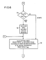
- the microprocessor program currently under consideration moves to block 66 wherein the program inquires as to whether the system is making its first iteration through the control loop. If the answer is "yes”, the program moves to portion A beginning at block 78. If, however, the answer is "no", the program continues with block 68 with the calculation of roadwheel deceleration rates A FL , A FR and A R .
- a FL and A FR correspond to the roadwheel rotational deceleration rates of the left and right front wheels, respectively, whereas A R corresponds to the rotational deceleration rate of the rear wheels of the vehicle. The deceleration rates are calculated by differentiating wheel rotational speeds with respect to time.
- wheel rotational velocity may be measured by any number of devices including those commonly in use with known anti-lock brake systems.
- the microprocessor further calculates total brake torque, BTQ, and the theoretical vehicular deceleration rate, A TH .
- Motor torque, T M is shown as being negative because positive motor torque is assumed to accelerate the vehicle in the forward direction.
- GR equals gear ratio of the axle drive gears coupled to the motor.
- a and B are constants which convert the rear and front brake pressures, respectively, to brake torques.
- a TH may be broadened to include a tolerance band to account for expected variations in loaded vehicle weight.
- system controller 30 compares the magnitude of A R to the magnitude of A TH . In the event that the magnitude of A R is less than the magnitude of A TH , the program transfers to point B and continues with block 74. If, however, A R exceeds A TH , this indicates that a skid is either occurring or is imminent because the rear wheels are decelerating rotationally at a rate which exceeds the normal rate of deceleration equivalent to the brake torque being produced by the braking system of the vehicle. Accordingly, at block 72 system controller 30 calculates MUE R , which is the coefficient of friction between the rear wheels and the road surface. Because a skid condition is imminent, the system controller will implement anti-lock measures as well.
- MUE R is calculated according to the following formula: where: L equals the length of the wheel base of the vehicle and D and H represent, respectively, the distance between the centre of gravity of the vehicle and the longitudinal centre line of the front wheels and the height of the centre of gravity over the road surface.
- system controller 30 implements anti-lock measures with respect to the rear axle.
- system controller 30 gives the command to rear brake control valve 52 to isolate rear hydraulic brake 34R from hydraulic pressure arising from master cylinder 42.
- System controller 30 will also give a signal to connect accumulator 54 to rear hydraulic brake 34R.
- the effect of these control commands will be that rear hydraulic brake 34R will receive no additional brake fluid from master cylinder 42; moreover, the hydraulic pressure existing within the cylinder of rear hydraulic brake 34R will be partially dissipated by the connection of accumulator 54 to the cylinder. As a result, the rear roadwheels will be given an opportunity to accelerate their rotational speeds and thereby move away from the skid threshold.
- the microprocessor inquires as to the rotational speeds of the front wheels. In similar fashion to that previously described with respect to the rear wheels, in the event that either A FL or A FR is greater than A TH , this indicates that a skid is present; if such is the case, the microprocessor moves to block 76 to immediately calculate MUE F and to implement anti-lock measures with respect to the front axle. If, however, a skid is not detected by virtue of the fact that A FL and A FR are less than A TH , the microprocessor continues to block 78. At block 76 MUE F is calculated according to the following equation: where: C equals distance between the centre of gravity of the vehicle and the horizontal centre line of the rear wheels.
- system controller 30 will give an appropriate command to front brake control valve 46 and accumulator 48 to isolate the wheel cylinders of front hydraulic brakes 34F from master cylinder 42 and to reduce the pressure within the front hydraulic brake cylinders by coupling the volume of accumulator 48 thereto.
- front roadwheels will be allowed to increase their rotational velocity to move away from the skidding or locking regime.
- system controller 30 uses the previously calculated values of MUE F and MUE R to calculate T F and T R , which are the maximum brake torque sustainable by the front and rear axles.
- T F and T R are calculated according to the following formulae:
- T REG is determined by using a look-up table contained in the ROM, in which the independent variables are motor speed and battery voltage. The reader will recall that T REG corresponds to the maximum regenerative brake torque available from the motor.
- T D total demand torque specified by the driver
- T R the total torque available at the rear roadwheels.
- T D total demand torque specified by the driver
- T R the total torque available at the rear roadwheels.
- T D is less than T R
- T D is compared to T REG . If T D is less than or equal to T REG , this indicates that the total torque demand specified by the driver is less than the regenerative torque capacity at the particular operating point in question.
- the point of operation could be, for example, from Figure 4 at line 1-1, with T REG3 specifying the regenerative torque available from traction motor 12.
- T HYDF and T HYDR will be set equal to zero.
- These variables correspond to the hydraulic brake torques desired from the front and rear axles, respectively.
- the total torque demand is capable of being satisfied by the motor operating regeneratively, while not exceeding the torque capability of the rear axle. As a result, there is no reason to employ hydraulic braking.
- T D is less than T R but greater than T REG
- T D is less than T R , and because T D is greater than T REG , this situation could correspond to operating point 0 ⁇ found in Figure 4 in the event that T REG1 is equal to the maximum regenerative torque. In this case, all of the regenerative torque could be utilized without exceeding the maximum torque capability of the rear axle. As a result, the strategy will apply front and rear hydraulic brakes in such fashion that both the front rear roadwheels will be operated at a substantially equivalent distance away from their skid points, where as before, equivalence is measured in terms of brake torque.
- DELTA (T R + T F - T D )/2 Accordingly, DELTA corresponds to the average difference between T D and the sum of T R and T F .
- a new value of T HYDF is calculated as the sum of T HYDF and T HYDR . This shifts the hydraulic braking entirely to the front wheels. At the same time, T HYDR is set equal to zero, thereby cancelling any hydraulic braking by the rear wheels.
- T D is greater than T R and T REG is less than T R .
- T HYDF is set equal to zero.
- the microprocessor compares the sum of T HYDR and T REG to T R . If the sum exceeds T R , this indicates that the hydraulic plus regenerative torque exceeds the brake torque sustaining capacity of the rear axle.
- TMP T HYDR + T REG - T R ;
- T HYDR T R - T REG ;
- T HYDF T HYDF + TMP.
- T D and T REG are greater than T R
- T MC -T R /GR
- T HYDF T D - T R
- T HYDR 0
- Friction brake operator 32 produces the desired torque commands by converting the required torques to brake system pressures and by operating the front and rear brake control valves 46 and 52 and accumulators 48 and 54 to increase and decrease the front and rear hydraulic brake pressures.
- the pressures will be decreased by isolating master cylinder 42 from the front and rear hydraulic brakes 34F and 34R and by coupling accumulators 48 and 54 with the wheel cylinders.
- brake pressure will be increase by isolating accumulators 48 and 54 from their respective brake assemblies and by opening front and rear control valves 46 and 52.
- Traction motor operator 36 operates traction motor 12 to produce the desired regenerative braking torque by controlling the current within the motor according to any of the several methods known to those skilled in the art and suggested by this disclosure.
- the algorithm returns to block 60.
- the various calculations described herein will then be reiterated; in the event that the roadwheel rotational deceleration rates A FL , A FR and A R are in excess of A TH , new values for MUE R and MUE F will be calculated. Then, the remainder of the algorithm will be completed. These periodic recalculations will continue until the roadwheels have been moved away from an incipient skidding or locking regime. It will thus be understood that the maximum sustainable braking torque is determined by adjusting the brake torques produced by the braking subsystems until the threshold deceleration rate is not exceeded. The brake torques are adjusted by modulating the motor torque command and the hydraulic torque commands until the roadwheels are being braked at a rate which is less than the threshold deceleration rate.
- the present system incorporates a method for operating regenerative and friction braking subsystems for a vehicle in which the first step includes producing a brake command signal having a magnitude corresponding to the level of braking force selected by the driver, followed by the step of determining maximum brake torques which may be developed by the friction and regenerative braking systems without causing skidding or slipping of the roadwheels of the vehicle and, finally, calculating brake commands for the friction and regenerative braking systems based upon the magnitude of the brake command signal and upon the determined maximum brake torques.
- the traction motor brake torque will be set equal to the maximum torque determined for the rear axle and the front wheel hydraulic brakes will develop the remaining portion of the desired brake torque without exceeding the maximum torque determined for the front wheels.
Applications Claiming Priority (2)
| Application Number | Priority Date | Filing Date | Title |
|---|---|---|---|
| US251421 | 1988-09-30 | ||
| US07/251,421 US4962969A (en) | 1988-09-30 | 1988-09-30 | Adaptive controller for regenerative and friction braking system |
Publications (3)
| Publication Number | Publication Date |
|---|---|
| EP0361708A2 true EP0361708A2 (de) | 1990-04-04 |
| EP0361708A3 EP0361708A3 (en) | 1990-11-22 |
| EP0361708B1 EP0361708B1 (de) | 1994-02-02 |
Family
ID=22951899
Family Applications (1)
| Application Number | Title | Priority Date | Filing Date |
|---|---|---|---|
| EP89309040A Expired - Lifetime EP0361708B1 (de) | 1988-09-30 | 1989-09-06 | Regler für regeneratives Bremssystem |
Country Status (5)
| Country | Link |
|---|---|
| US (1) | US4962969A (de) |
| EP (1) | EP0361708B1 (de) |
| JP (1) | JPH02120165A (de) |
| CA (1) | CA1325392C (de) |
| DE (1) | DE68912863D1 (de) |
Cited By (27)
| Publication number | Priority date | Publication date | Assignee | Title |
|---|---|---|---|---|
| WO1993001959A1 (de) * | 1991-07-24 | 1993-02-04 | Itt Automotive Europe Gmbh | Bremsanlage für kraftfahrzeuge mit elektrischem antrieb |
| EP0536639A1 (de) * | 1991-10-09 | 1993-04-14 | Iveco Magirus Aktiengesellschaft | Bremsanlage für Nutzkraftwagen mit Betriebs- und Dauerbremse |
| WO1993017898A1 (de) * | 1992-03-13 | 1993-09-16 | Robert Bosch Gmbh | Fahrzeugbremse |
| WO1993018949A1 (en) * | 1992-03-24 | 1993-09-30 | Lucas Industries Plc | Improved braking in electronic braking systems |
| WO1994018043A1 (en) * | 1993-02-01 | 1994-08-18 | Alliedsignal Inc. | Electropneumatic brake control with retarder apportioning |
| WO1994025322A1 (de) * | 1993-05-03 | 1994-11-10 | Itt Automotive Europe Gmbh | Bremsanlage für kraftfahrzeuge mit elektrischem antrieb |
| WO1995005299A1 (de) * | 1993-08-13 | 1995-02-23 | Itt Automotive Europe Gmbh | Blockiergeschützte bremsanlage für kraftfahrzeuge mit elektrischem antrieb |
| FR2721265A1 (fr) * | 1994-06-21 | 1995-12-22 | Renault | Procédé de contrôle du freinage récupératif sur un véhicule électrique. |
| EP0758591A1 (de) * | 1994-12-06 | 1997-02-19 | Mitsubishi Jidosha Kogyo Kabushiki Kaisha | Bremsregelvorrichtung für ein elektrisches motorfahrzeug |
| FR2745251A1 (fr) * | 1996-02-07 | 1997-08-29 | Bosch Gmbh Robert | Procede et dispositif de commande d'une installation de frein d'un vehicule |
| GB2325285A (en) * | 1996-02-06 | 1998-11-18 | Bosch Gmbh Robert | A motor vehicle with electric drive and friction braking |
| WO1999016636A1 (en) * | 1997-09-30 | 1999-04-08 | Crown Equipment Corporation | Intelligent braking system for materials handling vehicles |
| DE19810656A1 (de) * | 1998-03-12 | 1999-09-16 | Itt Mfg Enterprises Inc | Verfahren und Vorrichtung zum statischen oder dynamischen Ermitteln von Sollwerten für Bremskräfte oder Bremsmomente |
| GB2344799A (en) * | 1998-12-16 | 2000-06-21 | Rover Group | A motor vehicle braking system |
| FR2794705A1 (fr) * | 1999-06-09 | 2000-12-15 | Renault | Procede de commande pour le ralentissement d'un vehicule automobile a motorisation principale thermique |
| EP0940312A3 (de) * | 1998-03-03 | 2001-11-07 | General Motors Corporation | Fahrzeugbremsanlage mit dynamischer Bremsung des Antriebsstrangs |
| FR2819466A1 (fr) * | 2001-01-17 | 2002-07-19 | Bosch Gmbh Robert | Installation de regulation du couple de freinage d'un vehicule, procede de regulation du couple et circuit pour la mise en oeuvre |
| DE10135797A1 (de) * | 2001-07-23 | 2003-02-13 | Knorr Bremse Systeme | Bremssteuervorrichtung für Schienenfahrzeuge, die mit einer elektrischen Bremse und einer pneumatischen Bremse ausgestattet sind |
| DE10259878A1 (de) * | 2002-12-20 | 2004-07-01 | Zf Friedrichshafen Ag | Bremssystem und Verfahren zum Betrieb eines Bremssystems für elektrisch angetriebene Fahrzeuge |
| WO2006000560A1 (de) * | 2004-06-24 | 2006-01-05 | Continental Teves Ag & Co. Ohg | Verfahren zur steuerung eines bremssystems eines allradgetriebenen kraftfahrzeuges |
| FR2931426A1 (fr) * | 2008-05-20 | 2009-11-27 | Renault Sas | Systeme et procede de commande d'un vehicule a quatre roues motrices |
| WO2010037597A1 (de) | 2008-10-01 | 2010-04-08 | Robert Bosch Gmbh | Verfahren zum betrieb eines bremssystems in einem fahrzeug |
| WO2010049945A1 (en) * | 2008-10-31 | 2010-05-06 | Reva Electric Car Company Private Limited | Antilock braking for vehicles |
| DE102010052964A1 (de) | 2010-11-30 | 2012-05-31 | Valeo Schalter Und Sensoren Gmbh | Verfahren zum Betreiben eines Fahrzeugs und Fahrerassistenzeinrichtung |
| WO2015114430A1 (en) * | 2014-01-31 | 2015-08-06 | Toyota Jidosha Kabushiki Kaisha | Vehicle |
| RU2744524C1 (ru) * | 2019-10-23 | 2021-03-11 | Тойота Дзидося Кабусики Кайся | Устройство управления торможением |
| CN115257667A (zh) * | 2022-08-22 | 2022-11-01 | 东风柳州汽车有限公司 | 一种新能源中重卡车辅助制动分级控制方法及系统 |
Families Citing this family (93)
| Publication number | Priority date | Publication date | Assignee | Title |
|---|---|---|---|---|
| KR100201267B1 (ko) * | 1990-05-16 | 1999-06-15 | 가와모토 노부히코 | 전동차량의 회생제동장치 |
| US5090518A (en) * | 1990-05-31 | 1992-02-25 | General Motors Corporation | Brake control system |
| JPH04185204A (ja) * | 1990-11-20 | 1992-07-02 | Kubota Corp | 小型電動車 |
| DE69229961T2 (de) * | 1991-04-09 | 1999-12-23 | Honda Motor Co Ltd | Bremsregelsystem für ein elektrisches Fahrzeug |
| JP2782389B2 (ja) * | 1991-05-30 | 1998-07-30 | 日信工業株式会社 | ブレーキ装置 |
| DE4131169A1 (de) * | 1991-09-19 | 1993-03-25 | Wabco Westinghouse Fahrzeug | Verfahren zur abbremsung eines fahrzeugs |
| JP3189981B2 (ja) * | 1991-12-05 | 2001-07-16 | 本田技研工業株式会社 | 電動車両の制動装置 |
| US5318355A (en) * | 1991-12-05 | 1994-06-07 | Honda Giken Kogyo Kabushiki Kaisha | Brake system in electric vehicle |
| US5253929A (en) * | 1991-12-20 | 1993-10-19 | Toyota Jidosha Kabushiki Kaisha | Brake control system of electric vehicle |
| US5319292A (en) * | 1992-06-26 | 1994-06-07 | Harnischfeger Corporation | Method and apparatus for preventing motoring while braking |
| JP3305378B2 (ja) * | 1992-11-13 | 2002-07-22 | 本田技研工業株式会社 | 電動車両の制動装置 |
| DE4239386A1 (de) * | 1992-11-24 | 1994-05-26 | Teves Gmbh Alfred | Bremsanlage für Kraftfahrzeuge mit elektrischem Antrieb |
| US5472265A (en) * | 1992-12-10 | 1995-12-05 | Toyota Jidosha Kabushiki Kaisha | Antilock braking control apparatus for electric vehicle |
| US5358317A (en) * | 1993-01-07 | 1994-10-25 | Ford Motor Company | Fuzzy logic electric vehicle regenerative antiskid braking and traction control system |
| US5450324A (en) * | 1993-01-07 | 1995-09-12 | Ford Motor Company | Electric vehicle regenerative antiskid braking and traction control system |
| US5390992A (en) * | 1993-03-04 | 1995-02-21 | General Motors Corporation | Vehicle electric brake system with static brake torque control |
| JP2796039B2 (ja) * | 1993-05-14 | 1998-09-10 | 株式会社日立製作所 | 電気自動車の制動装置 |
| FR2705286B1 (fr) * | 1993-05-18 | 1995-09-08 | Smh Management Services Ag | Véhicule comprenant un système de freinage électrique et mécanique. |
| JP3430555B2 (ja) * | 1993-06-04 | 2003-07-28 | アイシン精機株式会社 | 電気自動車の回生制動によるアンチスキッド制御 |
| GB9320661D0 (en) * | 1993-10-07 | 1993-11-24 | Lucas Ind Public Limited | Electric vehicle having abs |
| US5378053A (en) * | 1993-12-07 | 1995-01-03 | Alliedsignal Inc. | Maximized regenerative braking vehicle braking controller |
| JP3348954B2 (ja) * | 1994-02-09 | 2002-11-20 | 株式会社日本自動車部品総合研究所 | 電気自動車の制動力制御装置 |
| US5423600A (en) * | 1994-02-14 | 1995-06-13 | General Motors Corporation | Brake system with brake gain shifting |
| US5362135A (en) * | 1994-02-14 | 1994-11-08 | General Motors Corporation | Brake system with adaptive offset compensation |
| US5539641A (en) * | 1994-02-14 | 1996-07-23 | General Motors Corporation | Brake control system method and apparatus |
| US5366281A (en) * | 1994-02-14 | 1994-11-22 | General Motors Corporation | Method of initializing a brake actuator |
| US5366280A (en) * | 1994-02-14 | 1994-11-22 | General Motors Corporation | Method of adaptively homing brake actuators |
| US5492192A (en) * | 1994-08-22 | 1996-02-20 | General Motors Corporation | Electric vehicle with traction control |
| US5511859A (en) * | 1995-08-25 | 1996-04-30 | General Motors Corporation | Regenerative and friction brake blend control |
| US6033041A (en) * | 1995-09-20 | 2000-03-07 | Mitsubishi Jidosha Kogyo Kabushiki Kaisha | Regenerative braking control system for electric vehicle |
| US5707115A (en) * | 1996-10-07 | 1998-01-13 | General Motors Corporation | Regenerative braking method |
| US6132016A (en) * | 1997-05-02 | 2000-10-17 | Hydro-Aire, Inc. | System and method for adaptive brake application and initial skid detection |
| US6325470B1 (en) | 1997-10-01 | 2001-12-04 | Visteon Global Technologies, Inc. | Method and apparatus for proportioning regenerative braking |
| US6099089A (en) * | 1997-11-01 | 2000-08-08 | Ford Motor Company | Method and apparatus for regenerative and friction braking |
| JP3365301B2 (ja) * | 1998-03-19 | 2003-01-08 | トヨタ自動車株式会社 | 車両の制動エネルギー制御装置とその制御方法 |
| US6062657A (en) * | 1998-04-21 | 2000-05-16 | Daimlerchrysler Rail Systems (North America) Inc. | Brake failure compensation system and method |
| US6155365A (en) * | 1998-05-12 | 2000-12-05 | Chrysler Corporation | Brake blending strategy for a hybrid vehicle |
| JP3896240B2 (ja) * | 2000-03-24 | 2007-03-22 | 住友電工ブレーキシステムズ株式会社 | 回生協調ブレーキシステムの制御方法 |
| US6278916B1 (en) * | 2000-05-09 | 2001-08-21 | Ford Global Technologies, Inc. | Torque control strategy for management of creep and grade hold torque in a wheeled vehicle whose powertrain includes a rotary electric machine |
| US6709075B1 (en) | 2000-08-07 | 2004-03-23 | Ford Global Technologies, Llc | System and method for braking an electric drive vehicle on a low Mu surface |
| DE10108909B4 (de) * | 2001-02-23 | 2010-11-04 | Linde Material Handling Gmbh | Verfahren zum Betreiben eines Fahrzeugs mit einem elektrischen Fahrmotor |
| US6488344B2 (en) | 2001-05-03 | 2002-12-03 | Ford Motor Company | Distribution of torque when driven wheels slip during regenerative braking |
| JP3811372B2 (ja) * | 2001-05-30 | 2006-08-16 | トヨタ自動車株式会社 | 車輌の制動力制御装置 |
| US6655754B2 (en) | 2002-04-02 | 2003-12-02 | Ford Global Technologies, Llc | Vehicle brake system having adaptive torque control |
| US6663197B2 (en) | 2002-04-02 | 2003-12-16 | Ford Global Technologies, Llc | Vehicle brake system having adaptive torque control |
| KR100534709B1 (ko) * | 2003-12-30 | 2005-12-07 | 현대자동차주식회사 | 전기자동차의 회생제동 제어 방법 및 장치 |
| US8066339B2 (en) * | 2004-03-09 | 2011-11-29 | Ford Global Technologies, Llc | Vehicle and method for controlling regenerative braking |
| US9630508B2 (en) | 2004-03-09 | 2017-04-25 | Ford Global Technologies, Llc | System and method for controlling regenerative braking in a vehicle |
| JP4659390B2 (ja) * | 2004-05-31 | 2011-03-30 | 富士重工業株式会社 | 車両制動装置および車両制動方法 |
| DE102005059373A1 (de) * | 2004-12-09 | 2006-06-14 | Continental Teves Ag & Co. Ohg | Verfahren zur Steuerung eines Bremssystems eines Kraftfahrzeuges |
| JP4654722B2 (ja) * | 2005-03-22 | 2011-03-23 | 株式会社アドヴィックス | 車両用ブレーキ装置 |
| JP4002279B2 (ja) * | 2005-06-27 | 2007-10-31 | 本田技研工業株式会社 | 車両のトラクション制御装置 |
| DE102006046093B4 (de) | 2006-09-28 | 2022-11-03 | Volkswagen Ag | Bremssystem und Verfahren zum Bremsen eines Fahrzeugs mit einem Hybridantrieb |
| US20100025167A1 (en) * | 2008-07-31 | 2010-02-04 | Caterpillar Inc. | Braking system for an off-highway machine involving electric retarding integrated with service brakes |
| DE102008036281B4 (de) * | 2008-08-04 | 2022-02-17 | Dr. Ing. H.C. F. Porsche Aktiengesellschaft | Fahrzeug mit wenigstens einer als Generator betreibbaren Elektromaschine und Verfahren zur Verzögerung eines Fahrzeugs |
| US8281908B2 (en) | 2008-08-29 | 2012-10-09 | Caterpillar Inc. | Brake cooling fluid diverter for an off-highway machine |
| US8410739B2 (en) * | 2008-09-15 | 2013-04-02 | Caterpillar Inc. | Method and apparatus for determining the operating condition of generator rotating diodes |
| US8140206B2 (en) | 2008-09-15 | 2012-03-20 | Caterpillar Inc. | Engine load management for traction vehicles |
| US7956762B2 (en) | 2008-09-15 | 2011-06-07 | Caterpillar Inc. | Method and apparatus for power generation failure diagnostics |
| US8253357B2 (en) | 2008-09-15 | 2012-08-28 | Caterpillar Inc. | Load demand and power generation balancing in direct series electric drive system |
| US9063202B2 (en) | 2008-09-15 | 2015-06-23 | Caterpillar Inc. | Method and apparatus for detecting phase current imbalance in a power generator |
| US7918296B2 (en) | 2008-09-15 | 2011-04-05 | Caterpillar Inc. | Cooling system for an electric drive machine and method |
| US7795825B2 (en) | 2008-09-15 | 2010-09-14 | Caterpillar Inc | Over-voltage and under-voltage management for electric drive system |
| US8324846B2 (en) | 2008-09-15 | 2012-12-04 | Caterpillar Inc. | Electric drive retarding system and method |
| US7996163B2 (en) | 2008-09-15 | 2011-08-09 | Caterpillar Inc. | Method and apparatus for detecting a short circuit in a DC link |
| US8054016B2 (en) | 2008-09-15 | 2011-11-08 | Caterpillar Inc. | Retarding energy calculator for an electric drive machine |
| US8231183B2 (en) * | 2009-02-19 | 2012-07-31 | Ford Global Technologies | Traction control method |
| DE102009056160B4 (de) * | 2009-11-27 | 2021-12-09 | Bayerische Motoren Werke Aktiengesellschaft | Verfahren zur Steuerung einer Antriebseinheit eines Kraftfahrzeugs |
| DE112010005337T5 (de) * | 2010-03-02 | 2012-12-13 | International Truck Intellectual Property Co., Llc | Reset-Funktion eines regenerativen Bremssystems und adaptive Kalibrierung für Hybrid- und Elektrofahrzeuge |
| US9527484B2 (en) | 2010-04-08 | 2016-12-27 | GM Global Technology Operations LLC | Regenerative braking control using a dynamic maximum regenerative braking torque calculation |
| KR101404087B1 (ko) * | 2010-05-12 | 2014-06-05 | 주식회사 만도 | 회생 제동 제어 방법 |
| US8626368B2 (en) | 2010-09-07 | 2014-01-07 | Caterpillar Inc. | Electric drive power response management system and method |
| US8764126B2 (en) | 2011-05-03 | 2014-07-01 | Robert Bosch Gmbh | Fuzzy logic based brake control |
| JP5832868B2 (ja) * | 2011-11-22 | 2015-12-16 | Ntn株式会社 | 電気自動車 |
| US8602142B2 (en) | 2011-12-13 | 2013-12-10 | Cummins Inc. | Hybrid vehicle braking adjustment for vehicle weight |
| DE102013207127A1 (de) * | 2012-06-12 | 2013-12-12 | Ford Global Technologies, Llc | Verfahren zum Anpassen eines Bremsvorgangs |
| DE102013208703A1 (de) * | 2013-05-13 | 2014-11-13 | Robert Bosch Gmbh | Steuervorrichtung für ein rekuperatives Bremssystem eines Fahrzeugs und Verfahren zum Abbremsen eines Fahrzeugs |
| US20150019058A1 (en) * | 2013-07-12 | 2015-01-15 | Stephan P. Georgiev | Regenerative braking regulation in automotive vehicles |
| KR101519227B1 (ko) * | 2013-10-18 | 2015-05-11 | 현대자동차주식회사 | 차량의 abs 동작 제어 방법 및 시스템 |
| JP2015093571A (ja) * | 2013-11-12 | 2015-05-18 | 日立オートモティブシステムズ株式会社 | 車両制御装置及び車両制御システム |
| US9238412B2 (en) * | 2014-03-18 | 2016-01-19 | GM Global Technology Operations LLC | Normalizing deceleration of a vehicle having a regenerative braking system |
| DE102014105984A1 (de) * | 2014-04-29 | 2015-10-29 | Dr. Ing. H.C. F. Porsche Aktiengesellschaft | Verfahren zur Bestimmung der Bremsmomentübersetzung |
| KR102264094B1 (ko) * | 2014-11-03 | 2021-06-14 | 현대모비스 주식회사 | 차량 자세 제어장치 및 제어방법 |
| US9637004B2 (en) | 2015-06-18 | 2017-05-02 | E-Aam Driveline Systems Ab | System and method for delimiting regenerative braking |
| JP6811062B2 (ja) * | 2016-09-15 | 2021-01-13 | 矢崎総業株式会社 | 回生制御装置 |
| US9958049B1 (en) | 2017-05-15 | 2018-05-01 | E-Aam Driveline Systems Ab | Electric drive module with Ravigneaux gearset |
| US10316946B2 (en) | 2017-10-13 | 2019-06-11 | E-Aam Driveline Systems Ab | Two mode electric drive module with Ravigneaux gearset |
| US10513186B1 (en) | 2017-11-01 | 2019-12-24 | Denis Vasilyevich Shchurovskiy | In-wheel electric motor with an increased electromagnetic flux and energy recovery brake |
| JP7146165B2 (ja) * | 2018-02-09 | 2022-10-04 | 株式会社アドヴィックス | 車両の制動制御装置 |
| US11124192B2 (en) | 2019-08-13 | 2021-09-21 | Ford Global Technologies, Llc | Electrified vehicle configured to selectively increase energy recovery threshold based on friction prediction and corresponding method |
| JP2021087235A (ja) * | 2019-11-25 | 2021-06-03 | トヨタ自動車株式会社 | 電動車両の制動装置 |
| US11958383B2 (en) | 2021-03-14 | 2024-04-16 | Toyota Motor Engineering & Manufacturing North America, Inc. | Regenerative braking control system |
| US20220289037A1 (en) * | 2021-03-14 | 2022-09-15 | Toyota Motor Engineering & Manufacturing North America, Inc. | Regenerative braking control system |
Citations (2)
| Publication number | Priority date | Publication date | Assignee | Title |
|---|---|---|---|---|
| US4074176A (en) * | 1976-06-07 | 1978-02-14 | Marine Electric Corporation | Motor protector |
| GB2036218A (en) * | 1978-11-28 | 1980-06-25 | Westinghouse Electric Corp | Vehicle dynamic brake control apparatus |
Family Cites Families (12)
| Publication number | Priority date | Publication date | Assignee | Title |
|---|---|---|---|---|
| US3131975A (en) * | 1960-04-21 | 1964-05-05 | North American Aviation Inc | Slope control wheel brake control system |
| US3924902A (en) * | 1973-08-31 | 1975-12-09 | Gen Signal Corp | Braking system for a light rail vehicle |
| DE2926017A1 (de) * | 1979-06-28 | 1981-02-12 | Teves Gmbh Alfred | Fahrzeugbremsanlage |
| JPS5653943A (en) * | 1979-10-09 | 1981-05-13 | Nissan Motor Co Ltd | Antiskid controller |
| FR2473464A1 (fr) * | 1980-01-11 | 1981-07-17 | Aerospatiale | Procede et dispositif pour le freinage d'un aeronef par recherche d'un glissement optimal des roues freinees |
| DE3027747A1 (de) * | 1980-07-22 | 1982-02-18 | Alfred Teves Gmbh, 6000 Frankfurt | Regelsystem fuer eine fahrzeugbremsanlage mit stroemungs- und reibungsbremse |
| JPS59154427U (ja) * | 1983-04-01 | 1984-10-17 | 日産自動車株式会社 | 4輪駆動車 |
| JPS59230856A (ja) * | 1983-06-14 | 1984-12-25 | Mazda Motor Corp | 電気自動車の制動装置 |
| US4591016A (en) * | 1984-03-19 | 1986-05-27 | General Motors Corporation | Brake system in a vehicle hybrid drive arrangement |
| US4576417A (en) * | 1985-02-04 | 1986-03-18 | General Motors Corporation | Power assisted braking system with wheel lock control |
| JPH0662080B2 (ja) * | 1985-11-14 | 1994-08-17 | トヨタ自動車株式会社 | 車両用アンチスキツド型ブレ−キシステム |
| JPH0624908B2 (ja) * | 1985-11-25 | 1994-04-06 | トヨタ自動車株式会社 | 鳴き防止機能を有する車両用ブレ−キシステム |
-
1988
- 1988-09-30 US US07/251,421 patent/US4962969A/en not_active Expired - Lifetime
-
1989
- 1989-08-02 CA CA000607363A patent/CA1325392C/en not_active Expired - Lifetime
- 1989-09-06 EP EP89309040A patent/EP0361708B1/de not_active Expired - Lifetime
- 1989-09-06 JP JP1231349A patent/JPH02120165A/ja active Pending
- 1989-09-06 DE DE89309040T patent/DE68912863D1/de not_active Expired - Lifetime
Patent Citations (3)
| Publication number | Priority date | Publication date | Assignee | Title |
|---|---|---|---|---|
| US4074176A (en) * | 1976-06-07 | 1978-02-14 | Marine Electric Corporation | Motor protector |
| US4074176B1 (en) * | 1976-06-07 | 1986-05-20 | Marine Electric Corp | Motor protector |
| GB2036218A (en) * | 1978-11-28 | 1980-06-25 | Westinghouse Electric Corp | Vehicle dynamic brake control apparatus |
Non-Patent Citations (1)
| Title |
|---|
| PATENT ABSTRACTS OF JAPAN vol. 9, no. 80 (M-370)(1803) 10 April 1985, & JP-A-59 209004 (NISSAN) 27 November 1984, * |
Cited By (45)
| Publication number | Priority date | Publication date | Assignee | Title |
|---|---|---|---|---|
| WO1993001959A1 (de) * | 1991-07-24 | 1993-02-04 | Itt Automotive Europe Gmbh | Bremsanlage für kraftfahrzeuge mit elektrischem antrieb |
| US5472264A (en) * | 1991-07-24 | 1995-12-05 | Itt Automotive Europe Gmbh | Brake unit for automotive vehicles with electric drive |
| EP0536639A1 (de) * | 1991-10-09 | 1993-04-14 | Iveco Magirus Aktiengesellschaft | Bremsanlage für Nutzkraftwagen mit Betriebs- und Dauerbremse |
| WO1993017898A1 (de) * | 1992-03-13 | 1993-09-16 | Robert Bosch Gmbh | Fahrzeugbremse |
| WO1993018949A1 (en) * | 1992-03-24 | 1993-09-30 | Lucas Industries Plc | Improved braking in electronic braking systems |
| WO1994018043A1 (en) * | 1993-02-01 | 1994-08-18 | Alliedsignal Inc. | Electropneumatic brake control with retarder apportioning |
| WO1994025322A1 (de) * | 1993-05-03 | 1994-11-10 | Itt Automotive Europe Gmbh | Bremsanlage für kraftfahrzeuge mit elektrischem antrieb |
| US5769509A (en) * | 1993-05-03 | 1998-06-23 | Itt Automotive Europe Gmbh | Brake unit for motor vehicles with electric drive |
| WO1995005299A1 (de) * | 1993-08-13 | 1995-02-23 | Itt Automotive Europe Gmbh | Blockiergeschützte bremsanlage für kraftfahrzeuge mit elektrischem antrieb |
| FR2721265A1 (fr) * | 1994-06-21 | 1995-12-22 | Renault | Procédé de contrôle du freinage récupératif sur un véhicule électrique. |
| EP0758591A1 (de) * | 1994-12-06 | 1997-02-19 | Mitsubishi Jidosha Kogyo Kabushiki Kaisha | Bremsregelvorrichtung für ein elektrisches motorfahrzeug |
| EP0758591A4 (de) * | 1994-12-06 | 1998-03-04 | Mitsubishi Motors Corp | Bremsregelvorrichtung für ein elektrisches motorfahrzeug |
| US5839800A (en) * | 1994-12-06 | 1998-11-24 | Mitsubishi Jidosha Kogyo Kabushiki Kaisha | Braking control system for electric automobile |
| GB2325285B (en) * | 1996-02-06 | 1999-07-28 | Bosch Gmbh Robert | Device for controlling the braking installation of motor vehicles with electric drive |
| GB2325285A (en) * | 1996-02-06 | 1998-11-18 | Bosch Gmbh Robert | A motor vehicle with electric drive and friction braking |
| FR2745251A1 (fr) * | 1996-02-07 | 1997-08-29 | Bosch Gmbh Robert | Procede et dispositif de commande d'une installation de frein d'un vehicule |
| WO1999016636A1 (en) * | 1997-09-30 | 1999-04-08 | Crown Equipment Corporation | Intelligent braking system for materials handling vehicles |
| US6236927B1 (en) | 1997-09-30 | 2001-05-22 | Crown Equipment Corporation | Intelligent braking system for materials handling vehicles |
| EP0940312A3 (de) * | 1998-03-03 | 2001-11-07 | General Motors Corporation | Fahrzeugbremsanlage mit dynamischer Bremsung des Antriebsstrangs |
| DE19810656A1 (de) * | 1998-03-12 | 1999-09-16 | Itt Mfg Enterprises Inc | Verfahren und Vorrichtung zum statischen oder dynamischen Ermitteln von Sollwerten für Bremskräfte oder Bremsmomente |
| US6457784B1 (en) | 1998-03-12 | 2002-10-01 | Continental Teves Ag & Co., Ohg | Method and device for statically or dynamically determining set values concerning braking forces or braking torque |
| GB2344799A (en) * | 1998-12-16 | 2000-06-21 | Rover Group | A motor vehicle braking system |
| FR2794705A1 (fr) * | 1999-06-09 | 2000-12-15 | Renault | Procede de commande pour le ralentissement d'un vehicule automobile a motorisation principale thermique |
| FR2819466A1 (fr) * | 2001-01-17 | 2002-07-19 | Bosch Gmbh Robert | Installation de regulation du couple de freinage d'un vehicule, procede de regulation du couple et circuit pour la mise en oeuvre |
| DE10135797C2 (de) * | 2001-07-23 | 2003-05-22 | Knorr Bremse Systeme | Bremssteuervorrichtung für Schienenfahrzeuge, die mit einer elektrischen Bremse und einer pneumatischen Bremse ausgestattet sind |
| DE10135797A1 (de) * | 2001-07-23 | 2003-02-13 | Knorr Bremse Systeme | Bremssteuervorrichtung für Schienenfahrzeuge, die mit einer elektrischen Bremse und einer pneumatischen Bremse ausgestattet sind |
| DE10259878A1 (de) * | 2002-12-20 | 2004-07-01 | Zf Friedrichshafen Ag | Bremssystem und Verfahren zum Betrieb eines Bremssystems für elektrisch angetriebene Fahrzeuge |
| US7925411B2 (en) | 2004-06-24 | 2011-04-12 | Continental Teves Ag & Co. Ohg | Method for controlling a brake system of a motor vehicle with all-wheel drive |
| WO2006000560A1 (de) * | 2004-06-24 | 2006-01-05 | Continental Teves Ag & Co. Ohg | Verfahren zur steuerung eines bremssystems eines allradgetriebenen kraftfahrzeuges |
| FR2931426A1 (fr) * | 2008-05-20 | 2009-11-27 | Renault Sas | Systeme et procede de commande d'un vehicule a quatre roues motrices |
| WO2009150346A1 (fr) * | 2008-05-20 | 2009-12-17 | Renault S.A.S. | Systeme et procede de commande d'un vehicule a quatre roues motrices |
| US8600596B2 (en) | 2008-05-20 | 2013-12-03 | Renault S.A.S. | System and method for controlling a four wheel drive vehicle |
| CN102171073B (zh) * | 2008-10-01 | 2015-04-01 | 罗伯特·博世有限公司 | 具有制动系统的车辆 |
| CN102171073A (zh) * | 2008-10-01 | 2011-08-31 | 罗伯特·博世有限公司 | 用于运行车辆中的制动系统的方法 |
| WO2010037597A1 (de) | 2008-10-01 | 2010-04-08 | Robert Bosch Gmbh | Verfahren zum betrieb eines bremssystems in einem fahrzeug |
| CN102325675A (zh) * | 2008-10-31 | 2012-01-18 | 马亨德拉雷瓦电动汽车私人有限公司 | 用于车辆的防抱死刹车系统 |
| WO2010049945A1 (en) * | 2008-10-31 | 2010-05-06 | Reva Electric Car Company Private Limited | Antilock braking for vehicles |
| US8612076B2 (en) | 2008-10-31 | 2013-12-17 | Mahindra Reva Electric Vehicles Pvt. Ltd. | Antilock braking for vehicles |
| DE102010052964A1 (de) | 2010-11-30 | 2012-05-31 | Valeo Schalter Und Sensoren Gmbh | Verfahren zum Betreiben eines Fahrzeugs und Fahrerassistenzeinrichtung |
| WO2012072464A1 (de) | 2010-11-30 | 2012-06-07 | Valeo Schalter Und Sensoren Gmbh | Verfahren zum betreiben eines fahrzeugs und fahrerassistenzeinrichtung |
| US9381897B2 (en) | 2010-11-30 | 2016-07-05 | Valeo Schalter Und Sensoren Gmbh | Method for operating a vehicle and driver assistance device |
| WO2015114430A1 (en) * | 2014-01-31 | 2015-08-06 | Toyota Jidosha Kabushiki Kaisha | Vehicle |
| RU2744524C1 (ru) * | 2019-10-23 | 2021-03-11 | Тойота Дзидося Кабусики Кайся | Устройство управления торможением |
| CN115257667A (zh) * | 2022-08-22 | 2022-11-01 | 东风柳州汽车有限公司 | 一种新能源中重卡车辅助制动分级控制方法及系统 |
| CN115257667B (zh) * | 2022-08-22 | 2023-07-25 | 东风柳州汽车有限公司 | 一种新能源中重卡车辅助制动分级控制方法及系统 |
Also Published As
| Publication number | Publication date |
|---|---|
| EP0361708A3 (en) | 1990-11-22 |
| US4962969A (en) | 1990-10-16 |
| JPH02120165A (ja) | 1990-05-08 |
| EP0361708B1 (de) | 1994-02-02 |
| CA1325392C (en) | 1993-12-21 |
| DE68912863D1 (de) | 1994-03-17 |
Similar Documents
| Publication | Publication Date | Title |
|---|---|---|
| EP0361708B1 (de) | Regler für regeneratives Bremssystem | |
| US5707115A (en) | Regenerative braking method | |
| US5450324A (en) | Electric vehicle regenerative antiskid braking and traction control system | |
| US8983748B2 (en) | Vehicle dynamics control device | |
| EP1234739B1 (de) | Bremssystem und -methode zum Bremsen eines Anhängers | |
| US6457784B1 (en) | Method and device for statically or dynamically determining set values concerning braking forces or braking torque | |
| US8548707B2 (en) | Braking system and method for braking a vehicle having a hybrid drive | |
| US7077484B2 (en) | Brake control for vehicle | |
| EP1447293B1 (de) | Bremssystem und Bremsverfahren für ein Motorfahrzeug | |
| US6325470B1 (en) | Method and apparatus for proportioning regenerative braking | |
| EP1555184B1 (de) | Bremsregelvorrichtung für Kraftfahrzeuge | |
| US6208920B1 (en) | Tire contact load control system | |
| US7441845B2 (en) | Method for operating multiple axle regenerative braking in an automotive vehicle | |
| US20050004738A1 (en) | Method for modifying a driving stability control of a vehicle | |
| US6890041B1 (en) | Antilock brake systems employing a sliding mode observer based estimation of differential wheel torque | |
| CN101484340B (zh) | 用于在车辆调节中补偿制动减速的方法 | |
| US20070112477A1 (en) | Optimization of a vehicle dynamics control using tire information | |
| EP0728644A2 (de) | Vorrichtung zur Lageregelung eines Fahrzeuges, bei dem Schlupfwinkel und Längskraft des Rades gesteuert sind | |
| KR20090062321A (ko) | 인 휠 드라이브 전기자동차의 독립구동 주행시스템과 그제어방법 | |
| US6099089A (en) | Method and apparatus for regenerative and friction braking | |
| US10981548B2 (en) | Method for compensating for low actuating dynamics of a mechanical brake of a transportation vehicle and control device | |
| JP3214141B2 (ja) | 制動力制御装置 | |
| JP2005028934A (ja) | 車両姿勢制御装置 | |
| US11548393B2 (en) | Braking method and system for an electric vehicle | |
| CN116101078A (zh) | 一种电动矿用自卸车自动速度控制系统及方法 |
Legal Events
| Date | Code | Title | Description |
|---|---|---|---|
| PUAI | Public reference made under article 153(3) epc to a published international application that has entered the european phase |
Free format text: ORIGINAL CODE: 0009012 |
|
| AK | Designated contracting states |
Kind code of ref document: A2 Designated state(s): DE FR GB |
|
| PUAL | Search report despatched |
Free format text: ORIGINAL CODE: 0009013 |
|
| AK | Designated contracting states |
Kind code of ref document: A3 Designated state(s): DE FR GB |
|
| 17P | Request for examination filed |
Effective date: 19901221 |
|
| 17Q | First examination report despatched |
Effective date: 19920320 |
|
| GRAA | (expected) grant |
Free format text: ORIGINAL CODE: 0009210 |
|
| AK | Designated contracting states |
Kind code of ref document: B1 Designated state(s): DE FR GB |
|
| PG25 | Lapsed in a contracting state [announced via postgrant information from national office to epo] |
Ref country code: DE Effective date: 19940202 Ref country code: FR Effective date: 19940202 |
|
| REF | Corresponds to: |
Ref document number: 68912863 Country of ref document: DE Date of ref document: 19940317 |
|
| EN | Fr: translation not filed | ||
| REG | Reference to a national code |
Ref country code: GB Ref legal event code: 746 Effective date: 19940727 |
|
| PLBE | No opposition filed within time limit |
Free format text: ORIGINAL CODE: 0009261 |
|
| STAA | Information on the status of an ep patent application or granted ep patent |
Free format text: STATUS: NO OPPOSITION FILED WITHIN TIME LIMIT |
|
| 26N | No opposition filed | ||
| REG | Reference to a national code |
Ref country code: GB Ref legal event code: IF02 |
|
| PGFP | Annual fee paid to national office [announced via postgrant information from national office to epo] |
Ref country code: GB Payment date: 20080808 Year of fee payment: 20 |
|
| REG | Reference to a national code |
Ref country code: GB Ref legal event code: PE20 Expiry date: 20090905 |
|
| PG25 | Lapsed in a contracting state [announced via postgrant information from national office to epo] |
Ref country code: GB Free format text: LAPSE BECAUSE OF EXPIRATION OF PROTECTION Effective date: 20090905 |