EP0359864B1 - Dispositif et procédé de mesure de champs magnétiques faibles, dépendant de la position et du temps - Google Patents
Dispositif et procédé de mesure de champs magnétiques faibles, dépendant de la position et du temps Download PDFInfo
- Publication number
- EP0359864B1 EP0359864B1 EP88115716A EP88115716A EP0359864B1 EP 0359864 B1 EP0359864 B1 EP 0359864B1 EP 88115716 A EP88115716 A EP 88115716A EP 88115716 A EP88115716 A EP 88115716A EP 0359864 B1 EP0359864 B1 EP 0359864B1
- Authority
- EP
- European Patent Office
- Prior art keywords
- gradiometers
- sensor arrangement
- amplifier
- processing system
- data processing
- Prior art date
- Legal status (The legal status is an assumption and is not a legal conclusion. Google has not performed a legal analysis and makes no representation as to the accuracy of the status listed.)
- Revoked
Links
Images


Classifications
-
- G—PHYSICS
- G01—MEASURING; TESTING
- G01R—MEASURING ELECTRIC VARIABLES; MEASURING MAGNETIC VARIABLES
- G01R33/00—Arrangements or instruments for measuring magnetic variables
-
- A—HUMAN NECESSITIES
- A61—MEDICAL OR VETERINARY SCIENCE; HYGIENE
- A61B—DIAGNOSIS; SURGERY; IDENTIFICATION
- A61B5/00—Measuring for diagnostic purposes; Identification of persons
- A61B5/24—Detecting, measuring or recording bioelectric or biomagnetic signals of the body or parts thereof
- A61B5/242—Detecting biomagnetic fields, e.g. magnetic fields produced by bioelectric currents
-
- G—PHYSICS
- G01—MEASURING; TESTING
- G01R—MEASURING ELECTRIC VARIABLES; MEASURING MAGNETIC VARIABLES
- G01R33/00—Arrangements or instruments for measuring magnetic variables
- G01R33/02—Measuring direction or magnitude of magnetic fields or magnetic flux
- G01R33/035—Measuring direction or magnitude of magnetic fields or magnetic flux using superconductive devices
- G01R33/0354—SQUIDS
-
- A—HUMAN NECESSITIES
- A61—MEDICAL OR VETERINARY SCIENCE; HYGIENE
- A61B—DIAGNOSIS; SURGERY; IDENTIFICATION
- A61B5/00—Measuring for diagnostic purposes; Identification of persons
- A61B5/0033—Features or image-related aspects of imaging apparatus classified in A61B5/00, e.g. for MRI, optical tomography or impedance tomography apparatus; arrangements of imaging apparatus in a room
- A61B5/0046—Arrangements of imaging apparatus in a room, e.g. room provided with shielding or for improved access to apparatus
Definitions
- the invention also relates to an operating method of such a device.
- Devices for measuring weak, location-dependent and time-dependent magnetic fields are becoming increasingly important for medical diagnostics, especially for measuring biomagnetic signals, ie signals emanating from sources in the body of a living being (cf. journal "Bild dermaschine", Issue 8, 1986, pages 76 to 83).
- Devices of this type must be able to measure the extremely weak biomagnetic signals, for example the magnetic fields emanating from the human brain or from the human heart, whose field strength is of the order of magnitude of 10 von12 T and below.
- Known biomagnetic measuring devices usually have a bearing device for receiving the examination object, a sensor arrangement for measuring magnetic fields, a holder for the sensor arrangement, means for adjusting the bearing device and the sensor arrangement relative to one another, and an electronic device for amplifying and evaluating the signals coming from the sensor arrangement which comprises a data processing system for evaluating the signals obtained with an output device for measurement results.
- a chamber for shielding magnetic fields (shielding chamber) surrounding the bearing device and the sensor arrangement can be provided.
- the sensor arrangement has one or more gradiometers (field measuring coils with assigned compensation coils) of first or higher order, a number of SQUIDs (Superconducting Quantum Interference Device) corresponding to the number of gradiometers, each gradiometer being inductively coupled to one of the SQUIDs, and one the vessel containing the gradiometers and the SQUIDs, a so-called cryostat, in which there is a temperature at which the SQUIDs and the gradiometers are superconducting.
- the cryostat is filled with liquid helium, i.e. there is a temperature of 4.2 K inside.
- the sensor arrangement In view of the low field strength of the magnetic fields to be measured, the sensor arrangement must deliver high quality signals which are free from environmental influences, e.g. Interference fields, high-frequency fields or mechanical vibrations, are caused interference.
- the signals originating from the sensor arrangement have to be processed in the data processing system in such a way that the results obtained by means of the data processing system are sufficiently exact that they correspond to the actual conditions.
- sensor arrangements have been developed which contain very well-matched second-order gradiometers which are matched to 10 ⁇ 4 or better, ie whose sensitivity to homogeneous fields is reduced by a factor of 104 or more (publication by Biomagnetic Technology Inc., San Diego, California: Design and Performance of a 14-Channel Neuromagnetometer ", Duane Crum et al., 1985)
- the sensor arrangement described here contains a total of 14 second order gradiometers, arranged in two cryostats, in groups of seven gradiometers each.
- a device of the type mentioned at the outset is from the article "Large-area low-noise seven-channel dc SQUID magnetometer for brain research" by Knuutila et al., Published in Review of Scientific Instrument 58 (11), November 1987, p. 2145 -2156 in connection with the article "Design, Construction, and Performance of a Large-Volume Magentic Shield” by Kelnos et al. appear in IEEE Transactions on Magnetics, Vol MAG-18, No. 1, Jan. 1982, pages 260-270.
- An array of seven gradiometers of the first order is arranged in a three-walled magnetic shielding chamber, each wall of the shielding chamber consisting of two crossed layers of metal that are pressed between aluminum plates.
- This nine-layer shielding chamber has very high shielding factors, for example in magnetic alternating fields with a frequency of 0.1 Hz the shielding factor is greater than 104 and above 0.5 Hz it is greater than 105.
- the shielding factor is greater than 104 and above 0.5 Hz it is greater than 105.
- only rough overview field line images can be generated from a single measurement, while detailed field line images can only be generated with several measurements in which the positions of the array are different.
- measurements must be taken several times in each measuring position, with the measured values being averaged will.
- the high shielding effort the measurement and localization of spontaneous, ie unforeseen, electrophysiological activities is not possible with such a device.
- the invention has for its object to design a device of the type mentioned in such a way that signals are obtained with the least possible outlay on equipment, which guarantee that their processing by means of an electronic data processing system leads to usable results.
- the invention is based on the object of specifying a method for operating a device of the type mentioned at the outset, which makes it possible to obtain results which correspond to reality as exactly as possible on the basis of signals obtained with the least possible outlay on equipment.
- the gradiometers for homogeneous magnetic fields are adjusted to less than 2 x 10 ⁇ 2. This can be achieved without special measures having to be taken in the manufacture of the gradiometer.
- the effort for the shielding chamber is also comparatively low in the case of the device according to the invention, since according to the invention no extremely high shielding effect is required.
- the shielding chamber should expediently have a shielding factor (field strength outside the shielding chamber based on the field strength inside the shielding chamber) in the order of magnitude of 1,000.
- the known DC-SQUIDs according to the invention differ from also known RF-SQUIDs in that DC-SQUIDs have a lower intrinsic noise than RF-SQUIDs.
- systems with seven channels in a coherent sensor area require the serial recording of the signals in different positions of the sensor arrangement so that a source can be detected.
- a system is required which allows the simultaneous recording of all signals necessary for source acquisition. If there are noise components in the signal, the minimum number of channels required for this is ten.
- the sensor arrangement contains at least twelve first order gradiometers, which are preferably exclusively gradiometers of the same type.
- a variant of the invention provides that the shielding chamber is designed such that the inhomogeneity of the residual magnetic field present in the interior of the shielding chamber during a measurement is less than 100 nT / m.
- This inhomogeneity of the residual field and the specified shielding factors can be achieved if the shielding chamber is constructed with two shells, the inner shell being made of mumetal, while the middle shell is made of aluminum.
- Such a shielding chamber also offers the advantage that the inner shell made of mumetal shields the magnetic noise, which is generated by eddy currents in the middle shell formed from aluminum, towards the interior of the shielding chamber containing the examination subject and the sensor arrangement.
- such a shielding chamber for high-frequency alternating fields has a shielding factor of at least 1,000.
- the shielding chamber can According to an embodiment of the invention, it can be provided with a demagnetizing device which acts on the shielding chamber with a demagnetizing field which, for demagnetizing the shielding chamber, can be reduced over at least four orders of magnitude, starting from the saturation field strength for mumetal. This measure further reduces the flux density and the inhomogeneity of the remaining field inside the shielding chamber.
- a particularly advantageous embodiment is obtained if the shielding chamber is constructed with three shells, with a further outer mumetal shell being attached in addition to the two-shell embodiment.
- a variant of the invention provides that the sensor arrangement and the bearing device are held in such a way that the changes in distance occurring between the sensor arrangement and the bearing device as a result of mechanical excitation during a measurement are less than 100 ⁇ m.
- the term mechanical excitation is to be understood to include all influences that can lead to undesirable changes in distance between the sensor arrangement and the bearing device, e.g. Shocks to the floor or sound waves. Only extremely small changes in distance due to mechanical excitation occur between the sensor arrangement and the bearing device if, according to a variant of the invention, a foundation for the shielding chamber is provided, on which the holder of the sensor arrangement and the bearing device are attached separately from one another. The foundation is preferably mounted on a sand bed and a direct mechanical connection between the holder of the sensor arrangement and the shells of the shielding chamber as well as the bearing device and the shells of the shielding chamber is avoided.
- the gradiometers are designed as axial gradiometers, the sensitivity of which to homogeneous magnetic fields is less than about 2 x 10 ⁇ 2.
- An axial gradiometer is a gradiometer whose field and compensation coils have a common central axis.
- the use of axial gradiometers offers the advantage that a higher number of gradiometers can be arranged in a given area than, for example, in the case of planar gradiometers in which the field and compensation coils lie side by side in one area.
- the signal intensity is correspondingly higher.
- the field coils of the gradiometers each enclose a preferably approximately circular area of at least 3.5 cm 2. It can be provided that the sensor surface containing the field coils of the gradiometer is approximately circular and has a diameter of at least 8 cm in diameter.
- the measures mentioned have the advantage that a sufficient measuring area is available for the area-wide detection of a source and the necessary minimum number of gradiometers can be arranged therein.
- the amplifier arrangement has a preamplifier, which is followed by a Lockin amplifier, the number of preamplifiers and the Lockin amplifier corresponding to the number of amplifier channels of the amplifier arrangement.
- an isolation amplifier is either connected between the preamplifier and the Lockin amplifier or connected downstream of the Lockin amplifier in each amplifier channel.
- the isolation amplifier is used to make a potential separation between the amplifiers. This avoids ground loops.
- a comb filter tuned to the frequency of the network and its integer multiples can be connected downstream of each amplifier channel in order to be able to filter out corresponding interference from the signals.
- an antialiazing filter can be provided between the isolation amplifier and the analog / digital converter in each amplifier channel in order to avoid artefacts occurring during the analog / digital conversion.
- a living being in addition to measuring magnetic signals, means connected to the data processing system for measuring at least one physiological function, e.g. the cardiac activity (EKG), the living being intended as the object to be examined. It is thus possible to interpret the results obtained depending on the physiological function measured.
- means for stimulating the senses of the living being provided as the object under examination can be present with the data processing system in order to be able to assess the effects of stimulating the senses of the living being on the results.
- a preferred variant of the invention provides that means for positioning the examination object on the bearing device in a defined position with respect to the bearing device and means for determining the spatial position of the sensor arrangement relative to the bearing device are provided. On the basis of the corresponding data, it is possible to determine the spatial position of the sensor arrangement in relation to the examination object by means of the data processing system, which is of particular importance for obtaining exact results.
- the calculation to be carried out by means of the data processing system as a model of the examination object can be based on a sphere or a half-space of homogeneous conductivity.
- the calculations carried out by means of the data processing system are based on the fact that brain and heart are preferred examination areas in living beings, the brain being modeled as a conductive sphere and the heart including the thorax as a conductive half-space in which the sources of magnetic signals are located as current dipoles.
- the output of the results in the form of the time course of the magnetic flux density of the source is particularly useful if, on the one hand, the quality of the signals is to be assessed from the shape of the curve and the time course, and on the other hand, diagnostic statements corresponding to conventional electrical methods (EEG, EKG) are to be obtained .
- the output of the results in the form of field line maps is particularly advantageous if the areal distribution of the signals, in particular with regard to a selection of sections accessible to further analysis, is considered and for the representation of the dynamics of the physiological processes.
- the output of the position of the spatial source as a result will be chosen if the examination can be used to draw conclusions regarding the spatial-temporal course of bodily functions or even for therapeutic measures derived therefrom. Examples are the detection of the foci of excitation in focal epilepsy of the brain or the conduction of the heart.
- a preferred embodiment of the method according to the invention provides that in the data processing system a by means of a sectional image device, e.g. by means of a magnetic resonance tomograph, the anatomical image of the examination object is stored and the results are output in such a way that the anatomical image, preferably a three-dimensional image, of the examination object is displayed, in which the position of the source is entered for a predetermined point in time of the measurement period is.
- This type of output of the results is particularly clear and informative. It can be provided that a sequence of preferably three-dimensional anatomical images, in each of which at least the spatial position of the source is entered, is output for successive times within the measurement period.
- a living being is provided as the object to be examined, it can be provided according to variants of the invention that the senses of the living being are stimulated during the measurement period, eg optically and / or acoustically, and the output of results takes place within the measurement period in which the senses of the living being are stimulated.
- a periodic physiological function of the living being is measured during the measurement period and stored as a function of time in digitized form in the data processing system.
- results it is then possible for results to be output for times at which the physiological function of the living being has a defined value. It is thus possible to assess the results obtained as a function of a stimulation of the senses of the living being or a physiological function of the living being.
- the device 1 shows a device according to the invention for measuring weak, location-dependent and time-dependent biomagnetic fields which originate from sources located in the interior of a human patient 1 provided as the examination subject.
- the device is also suitable for measurements on examination objects made of dead matter.
- the device according to the invention which is provided overall with reference number 2, is located in a hall 3 and is surrounded by an outer wall 4.
- the outer wall 4 is, for example, bricked, formed from plasterboard or made from sound-absorbing material and serves primarily to protect the device 2 from vibration and mechanical damage from the outside.
- the device 2 has a positioning device for the patient 1 designed as a patient couch 5, a sensor arrangement 7, which is suspended above the patient 1 on a holder 6 indicated by a dashed line and is also indicated by a dashed line, and serves to measure magnetic fields emanating from sources inside the patient 1.
- the sensor arrangement is aligned with a source Q located in the skull of patient 2.
- the device has an approximately cubic-shaped shielding chamber 8 which surrounds the patient couch 5 with the patient 1 lying thereon and the sensor arrangement 7, by means of which the measuring space 9 located inside the shielding chamber 8 is magnetically shielded.
- the shielding chamber 8 is of three-shell design, the inner shell 10 and the outer shell 11 each being made of mumetal, while the middle shell 12 is made of aluminum.
- the shielding chamber 8 has magnetic alternating fields with a frequency of 0.5 Hz a shielding factor of at least 10 for alternating magnetic fields with a frequency of 5 Hz a shielding factor of at least 100 and for alternating magnetic fields with a frequency of 50 Hz and above a shielding factor of at least 1000.
- the shielding chamber 8 has a shielding factor of at least 1,000.
- the inhomogeneity of the magnetic residual field present in the measuring space 9 under normal ambient conditions is less than 100 nT / m.
- the outer shell 11 is not absolutely necessary. Accordingly, this can also be omitted.
- the shielding chamber 8 is surrounded by coils 13a, 13b, 13c, which are connected to an alternating current generator 14 and form with it a demagnetizing device, by means of which the shielding chamber 8 can be acted upon by a demagnetizing field, which starts to demagnetize the shielding chamber over at least four orders of magnitude of the saturation field strength for mum metal, can be continuously reduced, which is indicated by an adjusting resistor 15 connected to the alternating current generator 14.
- the shielding chamber 8 is rigidly connected to a foundation base 17 of high mass via one or more brackets 16.
- the mass of the foundation base 17 should be in the order of 10 to 20 tons. It is preferably made of iron-free concrete.
- the rectangular foundation base 17 is placed on a sand bed 18.
- the hall 3 has a hall foundation 19 with a base plate which is mechanically separated from the foundation base 17 by an intermediate space 20.
- the intermediate space 20 is filled with a plastic foam 21. This measure ensures that mechanical vibrations from outside hall 3, which are caused, for example, by road traffic, are not transmitted directly to the foundation base 17.
- the shielding chamber 8 has a base plate 22 which is attached to the inner shell 10 in the region of the base of the shielding chamber 8.
- the shells 10, 11, 12 and the base plate 22 have a number of cutouts 23 in the area of the base of the shielding chamber 8, through which a post 24 or 25 is passed.
- the posts 24, 25 are made of an electrically insulating material, for example wood, ceramic or plastic. They are each firmly anchored to the foundation base 17 with their lower end.
- the holder 6 for the sensor arrangement 7 is fastened on a first number of posts, namely on the posts 24.
- the patient bed 5 is attached to a second number of posts, namely the posts 25, of which only one is visible.
- Movements of the patient 1 lying on the patient couch 5 must therefore first be directed via the posts 25 to the foundation base 17 before they can be transmitted from there via the posts 24 to the holder 6 and from there to the sensor arrangement 7. Conversely, this applies to any vibrations of the sensor arrangement 7. Because of the large mass of the foundation base 17, movements of the sensor arrangement 7 attached to the holder 6 relative to the patient bed 5 or the patient 1 lying thereon are largely suppressed. Likewise, vibrations which are excited by a doctor running on the base plate 22 can only be transmitted to the sensor arrangement 7 or the patient bed 5 via the mass of the foundation base 17. If transmission of vibrations of the base plate 22 to the shielding chamber 8 is undesirable, the base plate 22 can also be connected directly to the base base 17 in a manner not shown, via further posts.
- the holder 6 for the sensor arrangement 7 is shown, which has two vertical stand columns 26, the lower ends of which are firmly connected to the posts 24 and which are connected to one another at their upper ends via a cross strut 27.
- the tripod columns 26 are hollow on the inside and are therefore suitable for accommodating a counterweight 41 which can be displaced on the inside.
- Each counterweight 41 is connected to a common eyelet 30, which is fastened to the sensor arrangement 7, via a cable 28 which runs over deflection rollers 29 to the center of the hollow cross strut 27.
- a moving box 31 is attached in a vertically displaceable manner.
- the running boxes 31 are connected to one another via a bracket 32.
- the bracket 32 each has a circular disk segment 33 at its ends, which is rotatably mounted about a bolt 34 fastened to the associated moving case 31.
- a ring gear 35 is provided, on which a gear drive 36 engages.
- the bracket 32 can thus be pivoted about an axis extending through the bolts 34.
- a circular ring segment 37 is attached in the middle of the bracket 32.
- the circular ring segment 37 is provided with one or preferably a plurality of parallel circular segment-shaped grooves 38.
- the sensor arrangement 6 is pivotally mounted via sliding blocks attached to it.
- the swivel angle with respect to the vertical is labeled "Alpha”.
- the adjustment by the angle "Alpha” takes place via a spur gear.
- the Annular segment 37 is aligned parallel to the bow plane when pivoting.
- the height of the sensor arrangement 7 can be displaced relative to the circular ring segment 37 via a slide 39. The displacement always takes place in the radial direction, that is to say in the direction of the radius of the circular ring segment 37.
- the sensor arrangement 7 can also be rotated about its central axis 40 via a slide bearing (not shown).
- the entirety of the sensor arrangement 7, circular ring segment 37, bracket 32 and traveling boxes 31 can be displaced in height, that is to say relative to the stand columns 26.
- the cross strut 27 thus simultaneously serves as a bridge for a weight compensation between the weight of the sensor arrangement 7 on the one hand and the counterweights 41 sliding in the stand columns 26 on the other hand.
- the height adjustment is used to bring the sensor arrangement 7 with the sensor surface 42 indicated by dashed lines close to the patient 1.
- the sensor arrangement 7 can be displaced by the angle alpha along the grooves 38.
- the maximum angle alpha is approx. 50 ° on each side.
- a stop 43 is provided at each end in the grooves 38, which prevents the pivoted sensor arrangement 7 from hitting the stand column 26.
- the sensor surface 42 remains aligned with the same point P both when pivoting through the angle alpha and when the bracket is rotated.
- the point is usually placed in the head or chest of patient 1 at a location near which there is a source Q of magnetic signals.
- the distance between the sensor surface 42 and the point P can be varied with the aid of the slide 39.
- the gear drive 36 at least A worm gear 44 is assigned on one side, which comprises a worm wheel 45, a worm 46 and a handwheel 48 for adjustment.
- a worm gear 49 (with worm wheel 50, worm 51 and handwheel 52) is provided between slide 39 and circular ring segment 37, with the aid of which the swivel angle “alpha” can be adjusted and locked.
- Fig. 2 shows that the carriage 39 is divided into two parts 39a and 39b. The part 39a is seated in the groove 38 and the part 39b is displaceable in the radial direction relative to the part 39a (for example via a dovetail guide).
- the angle "alpha" results from the displacement of the part 39a along the groove 38, as a result of which the part 39b is also moved.
- a further worm gear 53 with the worm wheel 54, the worm 55 and the handwheel 56 is provided for the radial displacement of the part 39b relative to the part 39a.
- the position of the patient bed 5 together with the patient 1 relative to the sensor arrangement 7 can be detected in a manner known per se, for example with an arrangement of readable measuring shells which are assigned to the worm gears 44, 49, 53 in a manner not shown or are attached to the patient bed 5 .
- a scale 88 and a pointer 89 for determining the position of the patient couch 5 in its longitudinal direction with respect to the sensor arrangement 7 in FIG. 6 are exemplary drawn.
- the scale 88 assumes a defined position in relation to the sensor arrangement 7.
- the holder 6 and the patient couch 5 are formed in their entirety from materials other than ferromagnetic materials.
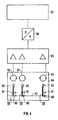
- the sensor arrangement 7 has an array of twelve gradiometers of the first order, each bearing the reference symbol 59, only some of the gradiometers 59 being shown in FIG. 4.
- Gradiometers 59 are axial gradiometers. These each have a field coil 60 and a compensation coil 61 connected to it in a known manner, the compensation coil 61 being wound in opposite directions to the corresponding field coil 60 and both having a common central axis.
- the compensation coil 61 of each gradiometer 59 is arranged in a plane which runs parallel to the plane of the corresponding field coil 60.
- the voltages induced in the field coil 60 and the compensation coil 61 cancel each other out in accordance with the comparison.
- the source of a magnetic field is in the vicinity of such a gradiometer 59, as is the case for an examination object located in the vicinity of the sensor arrangement 7, e.g. If the patient 1, the existing source is the case, the voltage induced in the field coil 60 is considerably greater than the voltage induced in the compensation coil 61. This has the advantageous effect that the field strength decreases very rapidly in the vicinity of the source.
- the gradiometers 59 provided in the case of the sensor arrangement described have a sensitivity reduced by a factor of 2 ⁇ 10 x2 for homogeneous magnetic fields. Such gradiometers can be implemented with little effort.
- the field coils 60 of the gradiometer 59 each enclose one Area of more than 3.5 cm2. If the field coils 60 have an approximately circular shape, as shown in FIG. 4, they have a diameter of more than 2.1 cm. Field coils 60 and compensation coils 61 are 7 cm apart.
- the gradiometers 59 are each connected to a coil 62 which serves to inductively couple the gradiometers with a DC-SQUID of an array of twelve SQUIDs.
- the gradiometers 59 and the SQUIDs 63 are therefore arranged in a schematically indicated thermal container, a so-called cryostat, which bears the reference number 64.
- the field coils 60 of the gradiometer 59 are arranged in a sensor area 42, indicated by dashed lines, closely behind the wall of the cryostat 64 opposite them.
- the individual SQUIDs 63 of the array are connected to an amplifier arrangement 65 to be described in greater detail, which is part of an electronic device for amplifying and evaluating the signals of the gradiometer 59, which, in addition to the amplifier arrangement 65, has an analog / digital converter 66 connected to its output , the output of which is connected to an electronic data processing system 67, which is used, among other things, for evaluating the signals coming from the gradiometers 59.
- the amplifier arrangement 65 contains a number of amplifier channels corresponding to the number of gradiometers 59 or SQUIDs 63, each of which is connected to one of the DC SQUIDs 63.
- the arrangement of twelve gradiometers in the sensor surface 42 of the sensor arrangement 7 is indicated schematically in the top view in FIG. 5. According to this figure, the selected arrangement results in good utilization of the available area, which is approximately circular in shape and has a diameter of approximately 10 cm.
- the field coils 60 of the gradiometers indicated in FIG. 5 each have a diameter of 2.1 cm and thus enclose an area of 3.5 cm 2.
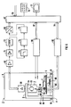
- FIG. 6 Further details regarding the amplifier arrangement 65 result from FIG. 6, in which the device according to the invention is shown with all essential mechanical and electronic components. Only one gradiometer 59 with the associated DC-SQUID 63 and the subsequent amplifier channel of the amplifier arrangement 65 is shown in this FIG.
- the other channels are constructed identically.
- an amplifier channel has a preamplifier 68 which is arranged in the region of the sensor arrangement 7 and is connected to the SQUID corresponding to the respective channel.
- the output signal of the preamplifier 68 arrives at a Lockin amplifier 69, which keeps the respective input signal at a constant level and whose feedback signal represents the output signal.
- An isolation amplifier 71 is connected to the Lockin amplifier 69, which isolates the potential between the amplifiers in order to avoid ground loops.
- the isolation amplifier 71 of each amplifier channel is followed by a comb filter 72, which is matched to the frequency of the electrical network and its integer multiples, to suppress interference caused by the electrical network.
- the comb filter 72 is followed by a steep-sided antialiazing filter 73, from which the signals each arrive at a sample and hold circuit 74.
- the sample and hold circuits 74 are connected via a 12-to-1 multiplexer 75 to the analog input of the analog / digital converter 66, which has its digital output to the data processing system 67 is connected.
- the sample and hold circuits 74, the 12to1 multiplexer 75 and the analog / digital converter 66 receive the respectively required control signals from the data processing system 67.
- the anti-aliasing filters 73 each have a time constant to avoid artifacts, which is at least twice the conversion time of the analog / digital converter 66 multiplied by twelve (number of channels). In principle, there is also the possibility of providing a separate analog / digital converter for each of the amplifier channels of the amplifier arrangement 65.
- the multiplexer 75 can then be omitted.
- the time constants of the antialiazing filter 73 can then be selected so that they correspond to at least twice the conversion time of the analog / digital converter. Compared to the arrangement described above, this results in a cut-off frequency which is higher by a factor corresponding to the number of channels, which in the case of exemplary embodiment is 12.
- the data processing system 67 comprises a central processing unit (CPU), a program memory and a data memory in a manner known per se and not shown.
- a keyboard 76 is connected to the data processing system 67 as an input device and a display device 77 is connected as an output device for results of the evaluation of the signals coming from the gradiometers 59.
- a printer and / or plotter can also be provided as the output device (not shown).
- the data processing system 67 also has an interface 78 via which it can be used with a sectional image device, not shown, e.g.
- a magnetic resonance tomograph can be connected, so that in addition to the data obtained by means of the analog / digital converter 66 from the signals of the sensor arrangement 7, preferably three-dimensional anatomical images of the examination object made by means of the sectional field device are stored in digitized form in the data memory of the data processing system 67 can be.
- the data processing system 67 also has an interface 79, to which a device schematically indicated in FIG. 6 for measuring at least one physiological function of patient 1, for example an EEG device 80 known per se, is connected.
- the data supplied by the EEG device 80 are also stored in digitized form in the data memory of the data processing system 67.
- patient 1 is lying on one side, his skull being supported by a cushion.
- the position of the patient bed 5 relative to the sensor arrangement 7 can e.g. detected by reading scales and entered into the data processing system 67 by means of the keyboard 76.
- a bite piece 83 which is firmly connected to the patient couch 5 and onto which the patient 1 lying on the patient couch 5 bites during the examination.
- Data relating to the position of the bite block 83 relative to the patient bed 5 are stored in the data processing system 67 so that it is able, based on this data and the data relating to the spatial position of the sensor arrangement 7 relative to the patient bed 5, the spatial position of the patient To determine the skull of the patient 1 relative to the sensor arrangement 7. If other parts of the body of the patient 1 than his skull are to be examined, other suitable means for producing a defined position of the patient 1 with respect to the patient bed 5 can be used instead of the bite block 83.
- a loudspeaker 84 and a light signal 85 are actuated in a suitable manner for the acoustic and / or optical stimulation of the senses of the patient 1 by means of control electronics 86 which are connected to the data processing system 67 via an interface 87.
- FIG. 7 A method for operating the device according to FIGS. 1 to 6 is shown in FIG. 7 in the form of a flow chart. Accordingly, the signals originating from the sensor arrangement 7, the data relating to the physiological function of the patient 1 and data indicating the times at which the patient 1 is stimulated, are recorded in the data processing system 67 and data relating to the position of the sensor arrangement 7 and the patient couch 5 is entered relative to one another into the data processing system 67 or is detected in the case of automatic sensors.
- the signals coming from the sensor arrangement 7 as well as the data relating to the physiological function of the patient 1 are represented individually in their temporal course or for several channels of the sensor arrangement 7, and if necessary after area-related allocation with the aid of data stored in the data processing system 67 with regard to the geometry the sensor arrangement 7 assigned to the positions of the individual gradiometers 59 and shown. Further signal parameters, such as the amplitude, can be derived from these results, optionally with additional use of the data relating to the times at which patient 1 is stimulated, and displayed as a field line map.
- the spatial position of the source Q can also be determined and in connection with one obtained by an imaging method and the anatomical image of the examined body region of the patient 1 stored in the data processing system 67 is displayed.
- the signals and data recorded by means of the data processing system 67 as well as signals and data derived therefrom, which are characterized in FIG. 7 by the fact that the corresponding information in the flowchart is marked with a blackened triangle, can be stored in a memory assigned to the data processing system 67, e.g. Magnetic disk or the like can be stored.
- FIG. 8 shows the time course of the magnetic flux density of a source.
- the time courses of the flux density, as obtained with the individual gradiometers 59 of an arrangement according to FIG. 5, are shown separately.
- the corresponding curves are shown in FIG. 8 in an arrangement relative to one another which corresponds to the arrangement of the gradiometer 59 according to FIG. 5.
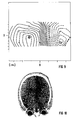
- FIG. 9 shows a field line map in which lines of the same magnetic flux density are entered for a plane which assumes a defined position with respect to a source Q.
- the field line map shows the conditions for a defined point in time within the measurement period.
- FIG. 10 finally shows a sectional image of an examination object, namely the skull of a human patient, obtained by means of magnetic resonance tomography, in which the position of a source Q is entered. It is a two-dimensional image. However, it is also possible to enter the determined spatial position of a source Q in three-dimensional images of an examination object.
Claims (31)
- Dispositif pour mesurer des champs magnétiques faibles, qui sont fonction du lieu et du temps et sont émis par une source (Q) située à l'intérieur d'un objet d'examen (1), lequel dispositif comprend :a) un dispositif de support (5) servant à recevoir l'objet d'examen (1),b) un dispositif de détection (7) possédant un réseau comprenant au moins dix gradiomètres du premier ordre (59), dans lequel chaque gradiomètre (59) possède une bobine inductrice (60) et une bobine de compensation correspondante (61) et des bobines inductrices (60) des gradiomètres (59) sont disposées dans une surface de détection (42), un réseau comprenant un nombre de dispostifs SQUID à courant continu (63), qui correspond au nombre des gradiomètres (59), chaque gradiomètre (59) étant accouplé inductivement à l'un des dispositifs SQUID à courant continu (63), et un récipient (64), qui contient les gradiomètres (59) et les dispositifs SQUID à courant continu correspondants (63) et dans lequel règne une température pour laquelle les dispositifs SQUID à courant continu (63) et les gradiomètres (59) sont supraconducteurs,c) un support (6) pour le dispositif de détection (7),d) des moyens (48,52,56,57,58) pour déplacer l'un par rapport à l'autre le dispositif de support (50) et le dispositif de détection (7) de telle sorte que le dispositif de détection (7) puisse être aligné sur des zones désirées de l'objet d'examen (1),e) une chambre (8) qui enveloppe le dispositif de support (5) et le dispositif de détection (7) et sert à réaliser un blindage vis-à-vis de champs magnétiques,f) la chambre de blindage magnétique (8) possédant un facteur de blindage égal au moins à 10 pour des champs magnétiques alternatifs d'une fréquence de 0,5 Hz, un facteur de blindage égal au moins à 100 pour des champs magnétiques alternatifs possédant une fréquence de 5 Hz, et un facteur de blindage égal au moins à 1000 pour des champs magnétiques alternatifs possédant une fréquence de 50 Hz et plus,g) un dispositif électronique servant à amplifier et évaluer les signaux des gradiomètres (50) et qui comporte un dispositif amplificateur (65) raccordé aux dispositifs SQUID à courant continu (63), un convertisseur analogique/numérique (66) raccordé au dispositif amplificateur (65), et une installation électronique de traitement des données (67) raccordée à ce convertisseur, le dispositif amplificateur (65) possédant un nombre de canaux amplificateurs, qui correspond au nombre des gradiomètres (59), et dont chacun est raccordé à l'un des dispositifs SQUID à courant continu (63), tandis que l'installation (67) de traitement de données comporte un dispositif de sortie (77) pour les résultats de l'évaluation des signaux des gradiomètres (59),caractérisé par le fait queh) la chambre de blindage (a) est constituée de deux coques, à savoir une coque extérieure réalisée en un matériau magnétique doux, dont la perméabilité relative est supérieure à 10⁴, et une coque extérieure en aluminium.
- Dispositif selon le préambule de la revendication 1, caractérisé en ce queh) la chambre de blindage (8) est formée de trois coques, les coques intérieure et extérieure (10 et 11) étant formées respectivement de mumétal, tandis que la coque médiane (12) est réalisée en aluminium.
- Dispositif suivant la revendication 1 ou 2, caractérisé par le fait que le dispositif de détection (7) cmporte au moins douze gradiomètres du premier ordre (59).
- Dispositif suivant l'une des revendications 1 à 3, caractérisé par le fait que le dispositif de détection (7) comporte exclusivement des gradiomètres (59) de même type.
- Dispositif suivant l'une des revendications 1 à 4, caractérisé par le fait que l'hétérogénéité du champ magnétique résiduel présent à l'intérieur de la chambre de blindage (8) pendant une mesure, est inférieure à 100 nT/m.
- Dispositif suivant l'une des revendications 1 à 5, caractérisé par le fait que la chambre de blindage (8) est raccordée à un dispositif de désaimantation (13a,13b,13c,14,15), qui charge la chambre de blindage (8) avec un champ de désaimantation qui peut être réduit continûment sur au moins quatre ordres de grandeur pour désaimanter la chambre de blindage.
- Dispositif suivant l'une des revendications 1 à 6, caractérisé par le fait que le dispositif de détection (7) et le dispositif de support (5) sont fixés de telle sorte que des variations de distance qui apparaissent entre le dispositif de détection (7) et le dispositif de support (5) sous l'effet d'une excitation mécanique lors d'une mesure, sont inférieures à 100 µm.
- Dispositif suivant l'une des revendications 1 à 9, caractérisé par le fait qu'il est prévu, pour la chambre de blindage (8), un socle (17), sur lequel le dispositif de fixation du dispositif de détection (7) et le dispositif de support (5) sont montés séparément l'un de l'autre.
- Dispositif suivant l'une des revendications 1 à 8, caractérisé par le fait que les gradiomètres (59) sont réalisés sous la forme de gradiomètres axiaux qui sont compensés à une valeur meilleure que 2 x 10⁻² pour des champs magnétiques homogènes.
- Dispositif suivant l'une des revendications 1 à 9, caractérisé par le fait que les bobines inductrices (60) des gradiomètres (59) enserrent respectivement une surface d'au moins 3,5 cm².
- Dispositif suivant l'une des revendications 1 à 10, caractérisé par le fait que la surface de détection (42), qui comporte les bobines inductrices (60) des gradiomètres (59), possède une forme approximativement circulaire et un diamètre égal à au moins 8 cm.
- Dispositif suivant l'une des revendications 1 à 11, caractérisé par le fait que le dispositif amplificateur (65) comporte un préamplificateur (68), en aval duquel est branché un amplificateur de verrouillage (69), le nombre des préamplificateurs (68) et des amplificateurs de verrouillage (69) correspondant respectivement au nombre des canaux amplificateurs.
- Dispositif suivant la revendication 12, caractérisé par le fait que dans chaque canal amplificateur, un amplificateur d'isolement (71) est branché entre le préamplificateur (68) et l'amplificateur de verrouillage (69) ou est branché en aval de l'amplificateur de verrouillage (69).
- Dispositif suivant la revendication 13, caractérisé par le fait qu'en aval de chaque canal amplificateur est branché un filtre en peigne (72) qui est réglé sur la fréquence du réseau électrique et sur les multiples entiers de cette fréquence.
- Dispositif suivant l'une des revendications 1 à 13, caractérisé par le fait qu'un filtre (73) de suppression des images fantômes est branché entre le dispositif amplificateur (65) et le convertisseur analogique/numérique (66), dans chaque canal amplificateur.
- Dispositif suivant l'une des revendications 1 à 15, caractérisé par le fait que des moyens (80), qui sont raccordés à l'installation de traitement de données (65), sont présents pour la mesure d'au moins une fonction physiologique d'un être vivant prévu en tant qu'objet d'examen (1).
- Dispositif suivant l'une des revendications 1 à 16, caractérisé par le fait que des moyens (84,85) raccordés à l'installation de traitement de données (67) sont prévus pour simuler les sens d'un être vivant prévu en tant qu'objet d'examen (1).
- Dispositif suivant l'une des revendications 1 à 17, caractérisé par le fait qu'il est prévu des moyens (83) pour positionner l'objet d'examen (1) sur le dispositif de support (5) dans une position définie par rapport au dispositif de support (5), et des moyens (88,89) pour déterminer la position spatiale du dispositif de détection (16) par rapport au dispositif de support (5).
- Procédé d'utilisation d'un dispositif suivant la revendication 18, selon lequela) pendant un intervalle de temps de mesure, les signaux provenant des gradiomètres (59) sont mémorisés en fonction du temps sous forme numérisée dans l'installation de traitement de données (67),b) pendant l'intervalle de temps de mesure, les données concernant la position spatiale du dispositif de détection (7) par rapport à l'objet d'examen (1) sont déterminées au moyen de l'installation de traitement de données (67), sur la base des données délivrées par les moyens (88,89) servant à déterminer la position spatiale du dispositif de détection (7) par rapport au dispositif de support (5), et sont mémorisées en fonction du temps, sous forme numérisée, dans l'installation de traitement de données (67),c) en partant d'un modèle de l'objet d'examen (1), sur la base des signaux délivrés par les gradiomètres (59) à des instants identiques pendant l'intervalle de temps de mesure et sur la base des données concernant la position spatiale du dispositif de détection (7) par rapport à l'objet d'examen (1), pour une source (Q) de signaux magnétiques, l'installation de traitement de données (67) calcule au choix,i. la variation dans le temps de la densité de flux magnétique de la source (Q),ii. la variation dans le temps de la densité de flux magnétique de la source (Q) dans une représentation correspondant à la disposition des gradiomètres,iii. à un instant prédéterminé dans un intervalle de temps de mesure une carte des lignes de champ, qui contient les lignes de même densité du flux magnétique, qui sont associées à une source (Q) pour un plan pouvant être défini librement, ouiv. à un instant prédéterminé pendant l'intervalle de temps de mesure, la position spatiale de la source (Q), etd) les résultats sont délivrés par l'intermédiaire du dispositif de sortie (77).
- Procédé suivant la revendication 19, caractérisé par le fait que pour le calcul devant être réalisé au moyen de l'installation de traitement de données (67), on part d'une sphère possédant une conductivité homogène en tant que modèle de l'objet d'examen (1).
- Procédé suivant la revendication 19, caractérisé par le fait que pour le calcul qui doit être exécuté au moyen de l'installation de traitement de données (67), on prend pour base un demi-espace possédant une conductivité homogène en tant que modèle de l'objet d'examen (1).
- Procédé suivant l'une des revendications 19 à 21, caractérisé par le fait qu'une succession de cartes de lignes de champ est délivrée à des instants successifs au cours de l'intervalle de temps de mesure.
- Procédé suivant l'une des revendications 19 à 21, caractérisé par le fait qu'une image anatomique de l'objet d'examen (1), qui est formée au moyen d'un appareil de tomographie, est mémorisée dans l'installation de traitement de données (67), et que la délivrance des résultats s'effectue lorsqu'intervient la représentation de l'image anatomique de l'objet d'examen (1), sur laquelle la position de la source (Q) est portée à un instant prédéterminé pendant l'intervalle de temps de mesure.
- Procédé suivant la revendication 23, caractérisé par le fait qu'une suite d'images anatomiques, sur lesquelles est marquée la position de la source (Q) est délivrée à des instants successifs pendant l'intervalle de temps de mesure.
- Procédé suivant l'une des revendications 19 à 24, caractérisé par le fait qu'un être vivant est prévu en tant qu'objet d'examen (1).
- Procédé suivant la revendication 25, caractérisé par le fait que les sens de l'être vivant sont stimulés pendant l'intervalle de temps de mesure.
- Procédé suivant la revendication 26, caractérisé par le fait que les sens de l'être vivant sont stimulés optiquement.
- Procédé suivant la revendication 26, caractérisé par le fait que les sens de l'être vivant sont stimulés acoustiquement.
- Procédé suivant l'une des revendications 26 à 28, caractérisé par le fait que la délivrance de résultats s'effectue, au cours de l'intervalle de temps de mesure, à des instants auxquels les sens de l'être vivant sont stimulés.
- Procédé suivant l'une des revendications 25 à 29, caractérisé par le fait que pendant l'intervalle de temps de mesure, une fonction physiologique périodique de l'être vivant est mesurée et est mémorisée, en fonction du temps, sous forme numérisée, dans l'installation de traitement de données (67).
- Procédé suivant la revendication 30, caractérisé par le fait que la délivrance de résultats s'effectue à des instants auxquels la fonction physiologique de l'être vivant possède une valeur définie.
Priority Applications (6)
| Application Number | Priority Date | Filing Date | Title |
|---|---|---|---|
| EP88115716A EP0359864B1 (fr) | 1988-09-23 | 1988-09-23 | Dispositif et procédé de mesure de champs magnétiques faibles, dépendant de la position et du temps |
| DE88115716T DE3886044D1 (de) | 1988-09-23 | 1988-09-23 | Einrichtung und Verfahren zur Messung von schwachen, orts- und zeitabhängigen Magnetfeldern. |
| FI894395A FI894395A (fi) | 1988-09-23 | 1989-09-18 | Anordning och foerfarande foer maetning av svaga, orts- och tidsberoende magnetfaelt. |
| JP1243251A JPH02116767A (ja) | 1988-09-23 | 1989-09-18 | 場所及び時間に関係して変化する弱い磁界の測定装置と方法 |
| US07/774,635 US5152288A (en) | 1988-09-23 | 1991-10-09 | Apparatus and method for measuring weak, location-dependent and time-dependent magnetic fields |
| US07/909,316 US5265611A (en) | 1988-09-23 | 1992-07-06 | Apparatus for measuring weak, location-dependent and time-dependent magnetic field |
Applications Claiming Priority (1)
| Application Number | Priority Date | Filing Date | Title |
|---|---|---|---|
| EP88115716A EP0359864B1 (fr) | 1988-09-23 | 1988-09-23 | Dispositif et procédé de mesure de champs magnétiques faibles, dépendant de la position et du temps |
Publications (2)
| Publication Number | Publication Date |
|---|---|
| EP0359864A1 EP0359864A1 (fr) | 1990-03-28 |
| EP0359864B1 true EP0359864B1 (fr) | 1993-12-01 |
Family
ID=8199356
Family Applications (1)
| Application Number | Title | Priority Date | Filing Date |
|---|---|---|---|
| EP88115716A Revoked EP0359864B1 (fr) | 1988-09-23 | 1988-09-23 | Dispositif et procédé de mesure de champs magnétiques faibles, dépendant de la position et du temps |
Country Status (5)
| Country | Link |
|---|---|
| US (1) | US5152288A (fr) |
| EP (1) | EP0359864B1 (fr) |
| JP (1) | JPH02116767A (fr) |
| DE (1) | DE3886044D1 (fr) |
| FI (1) | FI894395A (fr) |
Cited By (2)
| Publication number | Priority date | Publication date | Assignee | Title |
|---|---|---|---|---|
| DE102007017316A1 (de) | 2007-04-11 | 2008-10-30 | Bmdsys Gmbh | Messcontainer für biomagnetische Messungen |
| DE102008028259A1 (de) | 2008-06-13 | 2009-12-17 | Bmdsys Gmbh | Verfahren zur Verbindung hochpermeabler Teile einer magnetischen Abschirmung |
Families Citing this family (115)
| Publication number | Priority date | Publication date | Assignee | Title |
|---|---|---|---|---|
| FR2652928B1 (fr) | 1989-10-05 | 1994-07-29 | Diadix Sa | Systeme interactif d'intervention locale a l'interieur d'une zone d'une structure non homogene. |
| EP0470270A1 (fr) * | 1990-07-30 | 1992-02-12 | Siemens Aktiengesellschaft | Procédé de sélection, présentation et conversion graphique des signaux biomagnétiques ou bioélectriques positionables dans l'espace sur un écran d'image graphique |
| JPH07104403B2 (ja) * | 1990-09-07 | 1995-11-13 | ダイキン工業株式会社 | 磁場測定方法、およびその装置 |
| DE4104232A1 (de) * | 1991-02-12 | 1992-08-13 | Siemens Ag | Squid-messvorrichtung |
| EP0503108B1 (fr) * | 1991-03-11 | 1995-12-27 | Siemens Aktiengesellschaft | Système de mesure squid avec blindage |
| DE4125087C2 (de) * | 1991-07-29 | 2000-03-30 | Siemens Ag | Meßeinrichtung mit einer feldsensitiven Gradiometer-Schleifenanordnung und darin integriertem Gleichstrom-SQUID |
| DE4126949A1 (de) * | 1991-08-16 | 1993-02-18 | Siemens Ag | Verfahren zur signalauswertung bei biomagnetischen messeinrichtungen |
| US5265609A (en) * | 1991-08-28 | 1993-11-30 | Biomagnetic Technologies, Inc. | Nonmagnetic body movement detector and biomagnetometer utilizing the detector |
| US5220921A (en) * | 1991-10-25 | 1993-06-22 | Biomagnetic Technologies, Inc. | Nonmagnetic tactile stimulator and biomagnetometer utilizing the stimulator |
| JPH0614899A (ja) * | 1991-11-06 | 1994-01-25 | Mitsui Mining & Smelting Co Ltd | 脳磁界計測装置 |
| US5228443A (en) * | 1992-03-27 | 1993-07-20 | General Electric Company | Method for estimation and display of current source distribution from electric and magnetic measurements and 3D anatomical data |
| JP3106701B2 (ja) * | 1992-06-29 | 2000-11-06 | ダイキン工業株式会社 | 生体磁場計測装置 |
| JP3204542B2 (ja) * | 1992-07-24 | 2001-09-04 | 株式会社東芝 | 磁場源測定装置 |
| EP0582885A3 (en) * | 1992-08-05 | 1997-07-02 | Siemens Ag | Procedure to classify field patterns |
| US6757557B1 (en) | 1992-08-14 | 2004-06-29 | British Telecommunications | Position location system |
| CA2142338C (fr) | 1992-08-14 | 1999-11-30 | John Stuart Bladen | Systeme de localisation |
| US5313944A (en) * | 1992-09-21 | 1994-05-24 | Biomagnetic Technologies, Inc. | Measurement of internal body structure during biomagnetometry |
| DE4326043C2 (de) * | 1992-10-19 | 1995-08-17 | Siemens Ag | Verfahren zur Lokalisierung von mit starkem Rauschen überlagerten elektrophysilogischen Aktivitäten |
| DE4326041C2 (de) * | 1992-10-19 | 1995-11-16 | Siemens Ag | Verfahren zur Lokalisierung von mit starkem Rauschen überlagerten elektrophysiologischen Aktivitäten |
| DE4326044C2 (de) * | 1992-10-19 | 1995-08-17 | Siemens Ag | Verfahren zur zeitgemittelten Lokalisierung von mit starkem Rauschen überlagerten elektrophysiologischen Aktivitäten |
| US5532592A (en) * | 1993-02-02 | 1996-07-02 | Conductus, Inc. | Squid control apparatus with non-cryogenic flux-locked loop disposed in close proximity to the squid |
| DE4306037A1 (de) * | 1993-02-26 | 1994-09-08 | Siemens Ag | Gerät und Verfahren zum Verknüpfen mindestens eines aus einem Elektrokardiogramm lokalisierten Zentrums intrakardialer Aktivität mit einem Ultraschall-Schnittbild |
| US5458142A (en) * | 1993-03-19 | 1995-10-17 | Farmer; Edward J. | Device for monitoring a magnetic field emanating from an organism |
| US5617856A (en) * | 1993-09-24 | 1997-04-08 | Osaka Gas Company Limited | Biological information-measuring apparatus |
| DE4335102A1 (de) * | 1993-10-14 | 1995-04-20 | Fischer Ag | Einrichtung zur Ermittlung der Wirkung gepulster Magnetfelder auf einen Organismus |
| US5803089A (en) | 1994-09-15 | 1998-09-08 | Visualization Technology, Inc. | Position tracking and imaging system for use in medical applications |
| DE19510114A1 (de) * | 1995-03-21 | 1996-09-26 | Forschungsgesellschaft Fuer In | Einrichtung zum Messen magnetischer Remanenz |
| US5752513A (en) * | 1995-06-07 | 1998-05-19 | Biosense, Inc. | Method and apparatus for determining position of object |
| US5657756A (en) * | 1995-06-07 | 1997-08-19 | Ctf Systems Inc. | Method and systems for obtaining higher order gradiometer measurements with lower order gradiometers |
| US5592939A (en) | 1995-06-14 | 1997-01-14 | Martinelli; Michael A. | Method and system for navigating a catheter probe |
| US6239596B1 (en) | 1997-06-09 | 2001-05-29 | Joseph J. Stupak, Jr. | Total magnetic flux measuring device |
| US5836878A (en) * | 1997-08-11 | 1998-11-17 | Wisconsin Alumni Research Foundation | Head restraint method and apparatus for use in MRI |
| US6226548B1 (en) | 1997-09-24 | 2001-05-01 | Surgical Navigation Technologies, Inc. | Percutaneous registration apparatus and method for use in computer-assisted surgical navigation |
| US6842637B2 (en) | 1997-10-24 | 2005-01-11 | Hitachi, Ltd. | Magnetic field measurement apparatus |
| JP3237590B2 (ja) | 1997-10-24 | 2001-12-10 | 株式会社日立製作所 | 磁場計測装置 |
| US6021343A (en) | 1997-11-20 | 2000-02-01 | Surgical Navigation Technologies | Image guided awl/tap/screwdriver |
| US6348058B1 (en) | 1997-12-12 | 2002-02-19 | Surgical Navigation Technologies, Inc. | Image guided spinal surgery guide, system, and method for use thereof |
| US6477400B1 (en) | 1998-08-20 | 2002-11-05 | Sofamor Danek Holdings, Inc. | Fluoroscopic image guided orthopaedic surgery system with intraoperative registration |
| CA2356322A1 (fr) * | 1998-12-23 | 2000-06-29 | Peter D. Jakab | Scanner a resonance magnetique dote d'un dispositif electromagnetique de suivi de position et d'orientation |
| US6470207B1 (en) | 1999-03-23 | 2002-10-22 | Surgical Navigation Technologies, Inc. | Navigational guidance via computer-assisted fluoroscopic imaging |
| US6491699B1 (en) | 1999-04-20 | 2002-12-10 | Surgical Navigation Technologies, Inc. | Instrument guidance method and system for image guided surgery |
| US6493573B1 (en) | 1999-10-28 | 2002-12-10 | Winchester Development Associates | Method and system for navigating a catheter probe in the presence of field-influencing objects |
| US8239001B2 (en) | 2003-10-17 | 2012-08-07 | Medtronic Navigation, Inc. | Method and apparatus for surgical navigation |
| US7366562B2 (en) | 2003-10-17 | 2008-04-29 | Medtronic Navigation, Inc. | Method and apparatus for surgical navigation |
| US11331150B2 (en) | 1999-10-28 | 2022-05-17 | Medtronic Navigation, Inc. | Method and apparatus for surgical navigation |
| US8644907B2 (en) | 1999-10-28 | 2014-02-04 | Medtronic Navigaton, Inc. | Method and apparatus for surgical navigation |
| US6747539B1 (en) | 1999-10-28 | 2004-06-08 | Michael A. Martinelli | Patient-shielding and coil system |
| US6474341B1 (en) | 1999-10-28 | 2002-11-05 | Surgical Navigation Technologies, Inc. | Surgical communication and power system |
| US6235038B1 (en) | 1999-10-28 | 2001-05-22 | Medtronic Surgical Navigation Technologies | System for translation of electromagnetic and optical localization systems |
| AU1240801A (en) | 1999-10-28 | 2001-05-08 | Enterprise Medical Technology, Inc. | Coil structures and methods for generating magnetic fields |
| US6499488B1 (en) | 1999-10-28 | 2002-12-31 | Winchester Development Associates | Surgical sensor |
| US6381485B1 (en) | 1999-10-28 | 2002-04-30 | Surgical Navigation Technologies, Inc. | Registration of human anatomy integrated for electromagnetic localization |
| US8049597B1 (en) | 2000-01-10 | 2011-11-01 | Ensign Holdings, Llc | Systems and methods for securely monitoring an individual |
| US6725080B2 (en) | 2000-03-01 | 2004-04-20 | Surgical Navigation Technologies, Inc. | Multiple cannula image guided tool for image guided procedures |
| US6535756B1 (en) | 2000-04-07 | 2003-03-18 | Surgical Navigation Technologies, Inc. | Trajectory storage apparatus and method for surgical navigation system |
| US7536557B2 (en) * | 2001-03-22 | 2009-05-19 | Ensign Holdings | Method for biometric authentication through layering biometric traits |
| US7085400B1 (en) | 2000-06-14 | 2006-08-01 | Surgical Navigation Technologies, Inc. | System and method for image based sensor calibration |
| US6396268B1 (en) * | 2000-10-02 | 2002-05-28 | Ge Medical Systems Global Technology Company, Llc | Magnetic resonance imaging device having magnetic field disturbance compensation |
| JP3757815B2 (ja) * | 2001-04-27 | 2006-03-22 | 株式会社日立製作所 | 生体磁場計測装置 |
| US6636757B1 (en) | 2001-06-04 | 2003-10-21 | Surgical Navigation Technologies, Inc. | Method and apparatus for electromagnetic navigation of a surgical probe near a metal object |
| JP3866935B2 (ja) * | 2001-06-08 | 2007-01-10 | ジーイー・メディカル・システムズ・グローバル・テクノロジー・カンパニー・エルエルシー | 磁気共鳴撮影装置 |
| US6947786B2 (en) | 2002-02-28 | 2005-09-20 | Surgical Navigation Technologies, Inc. | Method and apparatus for perspective inversion |
| US6990368B2 (en) | 2002-04-04 | 2006-01-24 | Surgical Navigation Technologies, Inc. | Method and apparatus for virtual digital subtraction angiography |
| US7998062B2 (en) | 2004-03-29 | 2011-08-16 | Superdimension, Ltd. | Endoscope structures and techniques for navigating to a target in branched structure |
| US7197352B2 (en) * | 2002-08-26 | 2007-03-27 | Tristan Technologies, Inc. | High-resolution magnetoencephalography system, components and method |
| US7599730B2 (en) | 2002-11-19 | 2009-10-06 | Medtronic Navigation, Inc. | Navigation system for cardiac therapies |
| US7697972B2 (en) | 2002-11-19 | 2010-04-13 | Medtronic Navigation, Inc. | Navigation system for cardiac therapies |
| US7660623B2 (en) | 2003-01-30 | 2010-02-09 | Medtronic Navigation, Inc. | Six degree of freedom alignment display for medical procedures |
| US7542791B2 (en) | 2003-01-30 | 2009-06-02 | Medtronic Navigation, Inc. | Method and apparatus for preplanning a surgical procedure |
| US7313430B2 (en) | 2003-08-28 | 2007-12-25 | Medtronic Navigation, Inc. | Method and apparatus for performing stereotactic surgery |
| EP2316328B1 (fr) | 2003-09-15 | 2012-05-09 | Super Dimension Ltd. | Dispositif de fixation à enroulement pour utilisation avec des bronchoscopes |
| ES2387026T3 (es) | 2003-09-15 | 2012-09-11 | Super Dimension Ltd. | Dispositivo de fijación envolvente para utilizarse con broncoscopios |
| US7835778B2 (en) | 2003-10-16 | 2010-11-16 | Medtronic Navigation, Inc. | Method and apparatus for surgical navigation of a multiple piece construct for implantation |
| US7840253B2 (en) | 2003-10-17 | 2010-11-23 | Medtronic Navigation, Inc. | Method and apparatus for surgical navigation |
| US8764725B2 (en) | 2004-02-09 | 2014-07-01 | Covidien Lp | Directional anchoring mechanism, method and applications thereof |
| US7567834B2 (en) | 2004-05-03 | 2009-07-28 | Medtronic Navigation, Inc. | Method and apparatus for implantation between two vertebral bodies |
| FI117741B (fi) | 2004-09-10 | 2007-01-31 | Elekta Ab | Saumarakenne magneettisen suojahuoneen seinäelementtien välillä |
| US7835784B2 (en) | 2005-09-21 | 2010-11-16 | Medtronic Navigation, Inc. | Method and apparatus for positioning a reference frame |
| US9168102B2 (en) | 2006-01-18 | 2015-10-27 | Medtronic Navigation, Inc. | Method and apparatus for providing a container to a sterile environment |
| US8112292B2 (en) | 2006-04-21 | 2012-02-07 | Medtronic Navigation, Inc. | Method and apparatus for optimizing a therapy |
| US8660635B2 (en) | 2006-09-29 | 2014-02-25 | Medtronic, Inc. | Method and apparatus for optimizing a computer assisted surgical procedure |
| JP4893213B2 (ja) * | 2006-10-05 | 2012-03-07 | 株式会社日立製作所 | 磁場計測装置 |
| JP5022660B2 (ja) * | 2006-10-06 | 2012-09-12 | 株式会社日立ハイテクノロジーズ | 磁場計測装置 |
| US8905920B2 (en) | 2007-09-27 | 2014-12-09 | Covidien Lp | Bronchoscope adapter and method |
| US8150108B2 (en) * | 2008-03-17 | 2012-04-03 | Ensign Holdings, Llc | Systems and methods of identification based on biometric parameters |
| WO2009122273A2 (fr) | 2008-04-03 | 2009-10-08 | Superdimension, Ltd. | Système et procédé de détection d'interférence magnétique |
| WO2009147671A1 (fr) | 2008-06-03 | 2009-12-10 | Superdimension Ltd. | Procédé d'alignement basé sur des caractéristiques |
| US8218847B2 (en) | 2008-06-06 | 2012-07-10 | Superdimension, Ltd. | Hybrid registration method |
| US8932207B2 (en) | 2008-07-10 | 2015-01-13 | Covidien Lp | Integrated multi-functional endoscopic tool |
| US8165658B2 (en) | 2008-09-26 | 2012-04-24 | Medtronic, Inc. | Method and apparatus for positioning a guide relative to a base |
| US8175681B2 (en) | 2008-12-16 | 2012-05-08 | Medtronic Navigation Inc. | Combination of electromagnetic and electropotential localization |
| US8611984B2 (en) | 2009-04-08 | 2013-12-17 | Covidien Lp | Locatable catheter |
| US8494614B2 (en) | 2009-08-31 | 2013-07-23 | Regents Of The University Of Minnesota | Combination localization system |
| US8494613B2 (en) | 2009-08-31 | 2013-07-23 | Medtronic, Inc. | Combination localization system |
| US20160206226A1 (en) * | 2009-11-06 | 2016-07-21 | Senior Scientific Llc | Detection, Measurement, And Imaging Of Cells Using Cellular Internalization of Nanoparticles |
| WO2011159834A1 (fr) | 2010-06-15 | 2011-12-22 | Superdimension, Ltd. | Canal de travail expansible localisable, et procédé associé |
| EP2699068B1 (fr) | 2011-04-11 | 2016-08-17 | Sosnytskyy, Volodymyr Mykolayovych | Dispositif de protection d'unité de détection de magnétocardiographe |
| UA102163C2 (ru) | 2012-02-02 | 2013-06-10 | Владимир Николаевич Сосницкий | Устройство для компенсации электромагнитных помех при измерениях биомагнитных сигналов |
| US10952593B2 (en) | 2014-06-10 | 2021-03-23 | Covidien Lp | Bronchoscope adapter |
| CN104188650B (zh) * | 2014-09-26 | 2016-07-20 | 北京美尔斯通科技发展股份有限公司 | 非屏蔽式心磁图仪 |
| US10426555B2 (en) | 2015-06-03 | 2019-10-01 | Covidien Lp | Medical instrument with sensor for use in a system and method for electromagnetic navigation |
| US9962134B2 (en) | 2015-10-28 | 2018-05-08 | Medtronic Navigation, Inc. | Apparatus and method for maintaining image quality while minimizing X-ray dosage of a patient |
| US10478254B2 (en) | 2016-05-16 | 2019-11-19 | Covidien Lp | System and method to access lung tissue |
| US10722311B2 (en) | 2016-10-28 | 2020-07-28 | Covidien Lp | System and method for identifying a location and/or an orientation of an electromagnetic sensor based on a map |
| US10446931B2 (en) | 2016-10-28 | 2019-10-15 | Covidien Lp | Electromagnetic navigation antenna assembly and electromagnetic navigation system including the same |
| US10792106B2 (en) | 2016-10-28 | 2020-10-06 | Covidien Lp | System for calibrating an electromagnetic navigation system |
| US10751126B2 (en) | 2016-10-28 | 2020-08-25 | Covidien Lp | System and method for generating a map for electromagnetic navigation |
| US10418705B2 (en) | 2016-10-28 | 2019-09-17 | Covidien Lp | Electromagnetic navigation antenna assembly and electromagnetic navigation system including the same |
| US10638952B2 (en) | 2016-10-28 | 2020-05-05 | Covidien Lp | Methods, systems, and computer-readable media for calibrating an electromagnetic navigation system |
| US10517505B2 (en) | 2016-10-28 | 2019-12-31 | Covidien Lp | Systems, methods, and computer-readable media for optimizing an electromagnetic navigation system |
| US10615500B2 (en) | 2016-10-28 | 2020-04-07 | Covidien Lp | System and method for designing electromagnetic navigation antenna assemblies |
| US11219489B2 (en) | 2017-10-31 | 2022-01-11 | Covidien Lp | Devices and systems for providing sensors in parallel with medical tools |
| DE102018212858A1 (de) * | 2018-08-01 | 2020-02-06 | Siemens Healthcare Gmbh | Magnetresonanzeinrichtung, Magnetresonanzsystem und zugehöriges Betriebsverfahren |
| CN110464310B (zh) * | 2019-08-29 | 2022-08-09 | 山东百多安医疗器械股份有限公司 | 一种判断针灸疗效的极弱磁测定方法及针灸疗效测定装置 |
| CN110596619B (zh) * | 2019-09-16 | 2021-07-09 | 中国科学院上海微系统与信息技术研究所 | 一种全张量磁梯度测量组件及其优化方法 |
Family Cites Families (9)
| Publication number | Priority date | Publication date | Assignee | Title |
|---|---|---|---|---|
| US4079730A (en) * | 1974-10-02 | 1978-03-21 | The Board Of Trustees Of The Leland Stanford Junior University | Apparatus for measuring externally of the human body magnetic susceptibility changes |
| US4275744A (en) * | 1979-11-19 | 1981-06-30 | Wisconsin Alumni Research Foundation | Auditory response detection method and apparatus |
| US4744029A (en) * | 1984-08-31 | 1988-05-10 | Bio-Logic Systems Corporation | Brain electrical activity analysis and mapping |
| EP0210489B2 (fr) * | 1985-07-22 | 1993-11-18 | Siemens Aktiengesellschaft | Dispositif à plusieurs canaux pour mesurer des champs magnétiques faibles |
| DE8715844U1 (fr) * | 1986-12-09 | 1988-04-14 | Siemens Ag, 1000 Berlin Und 8000 Muenchen, De | |
| EP0277283B1 (fr) * | 1986-12-09 | 1993-03-31 | Siemens Aktiengesellschaft | Dispositif de mesure biomagnétique |
| US4736751A (en) | 1986-12-16 | 1988-04-12 | Eeg Systems Laboratory | Brain wave source network location scanning method and system |
| US4827217A (en) * | 1987-04-10 | 1989-05-02 | Biomagnetic Technologies, Inc. | Low noise cryogenic apparatus for making magnetic measurements |
| US4793355A (en) * | 1987-04-17 | 1988-12-27 | Biomagnetic Technologies, Inc. | Apparatus for process for making biomagnetic measurements |
-
1988
- 1988-09-23 DE DE88115716T patent/DE3886044D1/de not_active Expired - Fee Related
- 1988-09-23 EP EP88115716A patent/EP0359864B1/fr not_active Revoked
-
1989
- 1989-09-18 FI FI894395A patent/FI894395A/fi not_active Application Discontinuation
- 1989-09-18 JP JP1243251A patent/JPH02116767A/ja active Pending
-
1991
- 1991-10-09 US US07/774,635 patent/US5152288A/en not_active Expired - Fee Related
Cited By (4)
| Publication number | Priority date | Publication date | Assignee | Title |
|---|---|---|---|---|
| DE102007017316A1 (de) | 2007-04-11 | 2008-10-30 | Bmdsys Gmbh | Messcontainer für biomagnetische Messungen |
| DE102007017316B4 (de) * | 2007-04-11 | 2010-06-24 | Bmdsys Production Gmbh | Messcontainer für biomagnetische Messungen und biomagnetisches Messsystem |
| US8229541B2 (en) | 2007-04-11 | 2012-07-24 | Bmdsys Production Gmbh | Measuring container for biomagnetic measurements |
| DE102008028259A1 (de) | 2008-06-13 | 2009-12-17 | Bmdsys Gmbh | Verfahren zur Verbindung hochpermeabler Teile einer magnetischen Abschirmung |
Also Published As
| Publication number | Publication date |
|---|---|
| JPH02116767A (ja) | 1990-05-01 |
| DE3886044D1 (de) | 1994-01-13 |
| US5152288A (en) | 1992-10-06 |
| FI894395A0 (fi) | 1989-09-18 |
| EP0359864A1 (fr) | 1990-03-28 |
| FI894395A (fi) | 1990-03-24 |
Similar Documents
| Publication | Publication Date | Title |
|---|---|---|
| EP0359864B1 (fr) | Dispositif et procédé de mesure de champs magnétiques faibles, dépendant de la position et du temps | |
| US5265611A (en) | Apparatus for measuring weak, location-dependent and time-dependent magnetic field | |
| DE69632583T2 (de) | Verfahren und anordnung zur erhaltung von hoheren-ordnung-gradiometermessungen mit gradiometer von niedriger ordnung | |
| DE19633200C2 (de) | Verfahren und Vorrichtung zum Messen von Biomagnetismus | |
| EP0111826B1 (fr) | Dispositif à canaux multiples pour mesurer des champs magnétiques faibles engendrés par sources de champs différents | |
| EP1780556B1 (fr) | IRM utilisant des gradients de champ magnétique locaux et des bobines réceptrices locales | |
| DE102004022262A1 (de) | Magnetfeld-Messsystem | |
| EP0803738A1 (fr) | Méthode de synthèse d'image pour la production d'une image en combinant des images initiales | |
| EP0860706B1 (fr) | Procédé RM et dispositif pour déterminer la position d'une microbobine | |
| DE4325059A1 (de) | Gerät zum Messen von Magnetquellen | |
| DE102009055961A1 (de) | Verfahren zur Erfassung von einer Atembewegung eines Untersuchungsobjektes entsprechender Signaldaten mittels Magnetresonanz | |
| DE3247543A1 (de) | Vorrichtung zur mehrkanaligen messung schwacher, sich aendernder magnetfelder und verfahren zu ihrer herstellung | |
| DE19631916A1 (de) | Echtzeit-Messung von Temperaturveränderungen im lebenden Objekt mit Magnetresonanz-Abbildung | |
| EP0184225A3 (fr) | Procédé pour la tomographie à résonance nucléaire magnétique | |
| DE19905720A1 (de) | Fast-Spinecho-Impulsfolge für eine diffusions-gewichtete Abbildung | |
| DE3324208A1 (de) | Supraleitendes gradiometerspulensystem fuer eine vorrichtung zur mehrkanaligen messung schwacher, sich aendernder magnetfelder | |
| DE3233050C2 (de) | Verfahren der hochauflösenden Impuls-Kernresonanzspektroskopie | |
| DE60320376T2 (de) | Spulensystem für eine mr-vorrichtung und mit einem solchen spulensystem ausgestattete mr-vorrichtung | |
| DE3819541A1 (de) | Magnetresonanzbildgeraet | |
| DE4424842C1 (de) | Kompensation von Störfeldern bei NMR-Messungen im Erdmagnetfeld | |
| DE19653212A1 (de) | Verfahren und Vorrichtung zur Erhöhung der zeitlichen Auflösung von Magnet-Resonanz-Durchleuchtung | |
| EP1209481A1 (fr) | Procédé de correction d'erreurs de phase dans un procédé d'IRM temps réel | |
| EP0944025A2 (fr) | Procede et appareil d'imagerie pour des examens médicales | |
| EP0369538B1 (fr) | Procédé de tomographie par spin nucléaire pour déterminer la magnétisation nucléaire dans un nombre de couches parallèles | |
| DE2447496C3 (de) | Verfahren und Vorrichtung zum Messen der gyromagnetischen Resonanz eines Elementes in einer Probe |
Legal Events
| Date | Code | Title | Description |
|---|---|---|---|
| PUAI | Public reference made under article 153(3) epc to a published international application that has entered the european phase |
Free format text: ORIGINAL CODE: 0009012 |
|
| AK | Designated contracting states |
Kind code of ref document: A1 Designated state(s): BE DE FR GB IT NL |
|
| RBV | Designated contracting states (corrected) |
Designated state(s): BE DE FR GB NL |
|
| 17P | Request for examination filed |
Effective date: 19900425 |
|
| 17Q | First examination report despatched |
Effective date: 19920316 |
|
| GRAA | (expected) grant |
Free format text: ORIGINAL CODE: 0009210 |
|
| AK | Designated contracting states |
Kind code of ref document: B1 Designated state(s): BE DE FR GB NL |
|
| PG25 | Lapsed in a contracting state [announced via postgrant information from national office to epo] |
Ref country code: BE Effective date: 19931201 |
|
| REF | Corresponds to: |
Ref document number: 3886044 Country of ref document: DE Date of ref document: 19940113 |
|
| ET | Fr: translation filed | ||
| GBT | Gb: translation of ep patent filed (gb section 77(6)(a)/1977) |
Effective date: 19940211 |
|
| PGFP | Annual fee paid to national office [announced via postgrant information from national office to epo] |
Ref country code: GB Payment date: 19940815 Year of fee payment: 7 |
|
| PLBI | Opposition filed |
Free format text: ORIGINAL CODE: 0009260 |
|
| PGFP | Annual fee paid to national office [announced via postgrant information from national office to epo] |
Ref country code: FR Payment date: 19940920 Year of fee payment: 7 |
|
| PGFP | Annual fee paid to national office [announced via postgrant information from national office to epo] |
Ref country code: NL Payment date: 19940930 Year of fee payment: 7 |
|
| 26 | Opposition filed |
Opponent name: KANSAI RESEARCH INSTITUTE Effective date: 19940901 |
|
| NLR1 | Nl: opposition has been filed with the epo |
Opponent name: KANSAI RESEARCH INSTITUTE. |
|
| PG25 | Lapsed in a contracting state [announced via postgrant information from national office to epo] |
Ref country code: DE Effective date: 19950601 |
|
| RDAG | Patent revoked |
Free format text: ORIGINAL CODE: 0009271 |
|
| STAA | Information on the status of an ep patent application or granted ep patent |
Free format text: STATUS: PATENT REVOKED |
|
| 27W | Patent revoked |
Effective date: 19950701 |
|
| GBPR | Gb: patent revoked under art. 102 of the ep convention designating the uk as contracting state |
Free format text: 950701 |
|
| NLR2 | Nl: decision of opposition |