EP0359115B1 - Dispositif et procédé pour vider le contenu résiduel de bidons ou de bouteilles - Google Patents
Dispositif et procédé pour vider le contenu résiduel de bidons ou de bouteilles Download PDFInfo
- Publication number
- EP0359115B1 EP0359115B1 EP89116510A EP89116510A EP0359115B1 EP 0359115 B1 EP0359115 B1 EP 0359115B1 EP 89116510 A EP89116510 A EP 89116510A EP 89116510 A EP89116510 A EP 89116510A EP 0359115 B1 EP0359115 B1 EP 0359115B1
- Authority
- EP
- European Patent Office
- Prior art keywords
- bottles
- tins
- oil
- bottle
- tin
- Prior art date
- Legal status (The legal status is an assumption and is not a legal conclusion. Google has not performed a legal analysis and makes no representation as to the accuracy of the status listed.)
- Expired - Lifetime
Links
- 238000000034 method Methods 0.000 title claims description 8
- 239000007788 liquid Substances 0.000 claims abstract description 12
- 239000010705 motor oil Substances 0.000 claims abstract description 9
- 239000004033 plastic Substances 0.000 claims description 8
- 229920003023 plastic Polymers 0.000 claims description 8
- ATJFFYVFTNAWJD-UHFFFAOYSA-N Tin Chemical compound [Sn] ATJFFYVFTNAWJD-UHFFFAOYSA-N 0.000 claims 11
- 230000000779 depleting effect Effects 0.000 claims 1
- 239000003921 oil Substances 0.000 abstract description 66
- 239000002699 waste material Substances 0.000 abstract description 25
- 238000011084 recovery Methods 0.000 abstract 1
- 239000000463 material Substances 0.000 description 7
- 238000003780 insertion Methods 0.000 description 5
- 230000037431 insertion Effects 0.000 description 5
- 238000004064 recycling Methods 0.000 description 4
- 230000004888 barrier function Effects 0.000 description 2
- 239000012528 membrane Substances 0.000 description 2
- 239000002184 metal Substances 0.000 description 2
- 230000035515 penetration Effects 0.000 description 2
- 230000001154 acute effect Effects 0.000 description 1
- 210000003323 beak Anatomy 0.000 description 1
- 239000000945 filler Substances 0.000 description 1
- 230000000717 retained effect Effects 0.000 description 1
- 238000004904 shortening Methods 0.000 description 1
- XLYOFNOQVPJJNP-UHFFFAOYSA-N water Substances O XLYOFNOQVPJJNP-UHFFFAOYSA-N 0.000 description 1
Images


Classifications
-
- B—PERFORMING OPERATIONS; TRANSPORTING
- B65—CONVEYING; PACKING; STORING; HANDLING THIN OR FILAMENTARY MATERIAL
- B65F—GATHERING OR REMOVAL OF DOMESTIC OR LIKE REFUSE
- B65F1/00—Refuse receptacles; Accessories therefor
- B65F1/0033—Refuse receptacles; Accessories therefor specially adapted for segregated refuse collecting, e.g. receptacles with several compartments; Combination of receptacles
-
- B—PERFORMING OPERATIONS; TRANSPORTING
- B67—OPENING, CLOSING OR CLEANING BOTTLES, JARS OR SIMILAR CONTAINERS; LIQUID HANDLING
- B67B—APPLYING CLOSURE MEMBERS TO BOTTLES JARS, OR SIMILAR CONTAINERS; OPENING CLOSED CONTAINERS
- B67B7/00—Hand- or power-operated devices for opening closed containers
- B67B7/24—Hole-piercing devices
-
- B—PERFORMING OPERATIONS; TRANSPORTING
- B67—OPENING, CLOSING OR CLEANING BOTTLES, JARS OR SIMILAR CONTAINERS; LIQUID HANDLING
- B67B—APPLYING CLOSURE MEMBERS TO BOTTLES JARS, OR SIMILAR CONTAINERS; OPENING CLOSED CONTAINERS
- B67B7/00—Hand- or power-operated devices for opening closed containers
- B67B7/30—Hand-operated cutting devices
-
- B—PERFORMING OPERATIONS; TRANSPORTING
- B67—OPENING, CLOSING OR CLEANING BOTTLES, JARS OR SIMILAR CONTAINERS; LIQUID HANDLING
- B67C—CLEANING, FILLING WITH LIQUIDS OR SEMILIQUIDS, OR EMPTYING, OF BOTTLES, JARS, CANS, CASKS, BARRELS, OR SIMILAR CONTAINERS, NOT OTHERWISE PROVIDED FOR; FUNNELS
- B67C9/00—Devices for emptying bottles, not otherwise provided for
-
- B—PERFORMING OPERATIONS; TRANSPORTING
- B65—CONVEYING; PACKING; STORING; HANDLING THIN OR FILAMENTARY MATERIAL
- B65F—GATHERING OR REMOVAL OF DOMESTIC OR LIKE REFUSE
- B65F2240/00—Types of refuse collected
- B65F2240/152—Oil
-
- Y—GENERAL TAGGING OF NEW TECHNOLOGICAL DEVELOPMENTS; GENERAL TAGGING OF CROSS-SECTIONAL TECHNOLOGIES SPANNING OVER SEVERAL SECTIONS OF THE IPC; TECHNICAL SUBJECTS COVERED BY FORMER USPC CROSS-REFERENCE ART COLLECTIONS [XRACs] AND DIGESTS
- Y02—TECHNOLOGIES OR APPLICATIONS FOR MITIGATION OR ADAPTATION AGAINST CLIMATE CHANGE
- Y02W—CLIMATE CHANGE MITIGATION TECHNOLOGIES RELATED TO WASTEWATER TREATMENT OR WASTE MANAGEMENT
- Y02W30/00—Technologies for solid waste management
- Y02W30/10—Waste collection, transportation, transfer or storage, e.g. segregated refuse collecting, electric or hybrid propulsion
Definitions
- the invention relates to a method for largely emptying bottles or cans, to a device for emptying bottles or cans, to a deburring pliers for preparing the outlet rim of plastic bottles and cans, to a device for preparing the outlet rim of bottles or cans and on a collecting device when carrying out the method.
- Oil cans are usually opened with a mandrel that forms penetration openings with inwardly extending ridges on the bottom of the oil can.
- a drainer with a top flap is provided, which gives access to an obliquely arranged plate which is provided with a multiplicity of openings.
- the respective edge of the opening is provided with a ring of wires extending downwards, which are arranged along a conical jacket. Opened oil cans with residual contents can be hung diagonally down into the plate openings and the wire wreaths, and dripping oil is collected on a floor and collected in a collecting vessel.
- the residual content of the bottles or cans obtained with the method according to the invention can be put to a reasonable use.
- the cans or bottles are pre-cleaned to such an extent that the material of these cans or bottles can be reused.
- the emptying process can be applied in particular to motor oil, the adhesiveness of which is particularly high, so that larger amounts of such motor oil can be found in cans or bottles which are emptied per se and the yield with the system according to the invention becomes profitable.
- the material of the emptied cans or bottles is sent for recycling.
- the system according to the invention has a drip tray which has inclined drip trays or trays.
- these draining trays or trays can be moved around, which is why guides are provided on the rear wall of the box, into which these draining trays are suspended.
- the draining trays or trays are designed in the form of a gutter at their front edge. In this way, the liquid obtained can be passed directly into collecting vessels. However, it is also possible to collect the recovered liquid in the lower part of the drip box and to drain it into a collecting vessel via a drain screw or the like.
- the drainer holders have e.g. B. in the form of pens.
- the length of the pins above the drains can be changed, either by shortening the pins or by screwing them further into the plane of the drains.
- the holders can have a fir tree-like cross section.
- the neck rim of the waste cans can be trimmed free of burrs to completely empty cans for motor oil.
- special deburring pliers are provided, which make the opening edge of plastic cans free of burrs.
- a device for attaching an outlet opening with an outlet rim to a bottle or can which has a planer-like or bird of prey-like tool that cuts the outlet opening from the inside of the can or bottle, so that the opening edge with burrs pointing outwards is provided, which also favor the discharge of viscous liquid.
- the overall system also includes a collecting vessel for the bottles or cans with residual contents to be emptied.
- a domed lid with a feed channel is provided for the collecting vessel.
- the throw-in channel is designed as protection against the ingress of rainwater, and a flap through the opening through the lid ensures that the anteroom to the collecting vessel is also protected from the wind.
- Oil cans are usually made of plastic and have an approximate bottle shape, the neck opening being closed with a membrane which has to be pierced in order to remove the fresh oil. Because of this membrane, which forms a ridge, the oil can cannot empty completely, even if the driver holds the oil can for a very long time on the oil filler neck of his engine.
- the lack of emptying of the motor oil can is unfortunate not only because of the loss of fresh oil, but also with regard to recycling the plastic material of the oil can.
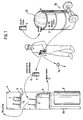
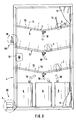
- waste oil cans 1 are collected in a barrel 2, which, for. B. get the customers at gas stations, and such collected waste oil cans are deburred using a deburring pliers 3, after which the waste oil can has a smooth opening edge 6 and is considered prepared.
- the prepared waste oil cans 1 are placed in an oil drip box 4, which has slanted drip trays 5 with which the opening edge 6 of the prepared waste can in Is brought into contact.
- the cans 1 are slightly inclined on the draining plates 5.
- This edge contact creates a continuous surface between the draining surface 5 and the interior of the prepared waste can, so that the surface tension of the remaining fresh oil in the can does not prevent the fresh oil from being completely removed from the can to drain.
- This remaining fresh oil flows along the drip tray 5 into a channel 7 and can be collected in a vessel 8.
- a barrel 9 can be placed below an oil drain screw on the oil drip box 4 to collect the oil.
- the draining time of the prepared waste oil cans 1 in the drainer 4 can be selected to be very long, for example over a day, practically no residual oil is found in the waste oil cans, and plastic material can be obtained again from the waste oil cans (recycling).
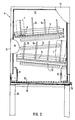
- FIGS. 1 and 3 show the oil drip box 4 from the front and from the side, respectively, in FIG. 2 the door 11 being largely broken away to reveal the view inside the box.
- Rails 13 are attached to the rear wall 12, with a certain slope, as can be seen.
- the drains 5 made of sheet metal are suspended in these rails and also have a certain slope to the front, as shown in FIGS. 1 and 3.
- a number of pins 14 are attached to the drains 5, the length of which is selected to match the size of the waste oil cans to be completely emptied.
- the waste oil cans 1 must rest on one side with their edge 6 on the surface of the drainer 5, which is why the pins 14 must not be too long, while on the other hand the waste oil cans 1 should be prevented from falling over.
- the wall bottom 15 of the oil drip box 4 is inclined and leads to an oil drain screw 16, which can also be arranged differently from FIG. 2 below the oil box 4.
- a grate can be 17 can be arranged, on which the oil collecting vessels 8 can be placed, as shown.
- the upper drip tray 5 is inclined to the left in the drawing, so that the recovered oil collects in the left vessel 8, while the lower drip tray 5 is inclined to the right, with the result that the recovered fresh oil is found in the right vessel 8.
- the rear wall 12 is retracted at its upper end and forms a rear gripping strip 18, so that the oil drip box can be hung on a wall.
- a base frame 19 it is also possible to provide a base frame 19 in order to mount the oil drain box 4 in a free-standing manner.
- FIG. 4 shows an enlarged detail Z from FIG. 3.
- the pin 14 can consist of a screw bolt 21 and a tightly wound coil spring 22 which is attached to the upper end of the screw bolt 21 and optionally also soldered on.
- the fastening in a hole in the sheet metal 5 takes place via two nuts 23 which clamp the edge of the hole.
- the coil spring 22 can be easily shortened if necessary so that the appropriate length of the pin 14 can be adapted to the requirements.
- the deburring pliers 3 are shown, with which the waste oil can can be prepared in such a way that the opening edge becomes burr-free in order to enable the fresh oil to be completely emptied.
- the deburring pliers have two legs 31, 32 which are connected to one another via an axle rivet 33 and can be pivoted against one another in order to widen and close the jaws 30.
- the pliers have handles 34.
- the legs 31, 32 each curve around the pliers mouth 30, in which the neck of the waste oil can is to be grasped.
- the legs 31 and 32 have respective guide edges 35 and 36 which are to be placed on the opening edge of the waste oil can from above.
- Arc-shaped extend parallel to the guide edges 35, 36 Retaining tabs 37, 38, on which cutting blades 39, 40 are attached, the cutting edges being opposed and projecting into the pliers mouth 30.
- the front end of the deburring pliers can also be designed as scissors 41.
- the pliers jaw 30 takes on a shape which matches the neck of the oil can, and the support edges 35, 36 form a guide for the upper edge of the oil can so that it can be rotated.
- the cutting edges of the blades 39, 40 come into engagement with the neck of the oil can, and by rotating the pliers relative to the oil can, a neck ring 1 a can be separated off, so that the prepared waste oil can is obtained, which has a burr-free edge 6 .
- the blades 39, 40 are fastened interchangeably, for example screwed on, and can be exchanged for new blades if required.
- the area 42 between the legs 31, 32 can also be designed with notched, curved edges, in order to be able to grip screw closures better.
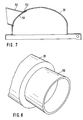
- FIG. 7 and 8 show a curved barrel lid 20 which is provided with a tubular insertion channel 50 for waste oil cans.
- the insertion channel 50 is long enough and approximately horizontally arranged to shield rain from its interior. For this reason, the front edge of the insertion channel 50 is slightly overhanging and sloping.
- the curved barrel cover 20 has a circular cutout in the region of the insertion channel 50, and this circular cutout is covered by a rubber flap 51 which is fastened at 52 inside the barrel cover 20.
- the rubber material of the flap 51 is sufficiently flexible so that waste oil cans can be pushed into the interior of the barrel lid 20 and resilient enough to cover and close the cut-out opening.
- the barrel lid 20 is attached to the barrel 2 with a clamping ring, not shown, which, moreover, with a transport cart 70 can be moved. (Further details are disclosed in applicant's EP 88 106 176.6.)
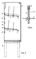
- FIG. 9 shows a second embodiment of the oil drip box 4 with the door 11 largely broken away, the same reference numerals being used as in the first embodiment according to FIGS. 2 and 3.
- the oil drip box is intended to be placed on the floor, and there are three drip trays 5 and space for three vessels 8 which are connected to the deepest points of the trays 5 via respective hose lines 10.
- the bottoms 5 are slightly inclined towards the center and towards the front in order to open into a channel 7, as is similarly shown in FIG. 3.
- a device 60 for making an opening with an outlet rim 6 on a bottle or can 1 is provided on the drainer according to FIG. 9.
- the device 60 comprises a foot lever 61, as shown in more detail in FIG. 10, and an actuating device 62 for a beak-like tool 63 (FIG. 11).
- the actuating device 62 has a working cylinder 64 with a piston rod 65 and two interconnected double-armed levers 66 and 67, which are each pivotably mounted at 68 and 69 and coupled to one another at 71.
- the piston rod 65 is coupled to the lever 66 at 72. Accordingly, when the working cylinder 64 makes a working stroke, the lever 66 in FIG.
- the contact jaws 73 serve to support a bottle or can 1 into which an opening with an outlet edge 6 is to be torn.
- the tool 63 has a certain resemblance to the beak of a bird of prey, ie the cutting edges are arcuate and meet at an acute angle in a tip which first penetrates the wall of the bottle or can 1. In the illustrated embodiment, this is a Can jacket from which a triangular piece is cut. It is important, however, that the bottom of the can 1 is cut through from above by the tool 63, so that the edge of the outlet opening formed is provided with a ridge which forms a good drip edge.
- an edge formed in this way is referred to as an outlet edge.
- a barrier edge In the usual way of opening cans, a barrier edge has always been created, which is why the cans cannot be completely emptied.
- the new way of creating the opening with burrs pointing outwards enables complete emptying of cans.
- the device 60 for attaching an outlet opening can be operated pneumatically, hydraulically or electrically, but also with foot power.
- a cap 74 is pivoted over the tool 63 and the lever 67 is secured by means of a bolt 75.
- Fig. 12 shows that in addition to the pin 14, a further pin 76 can be provided, which is provided with a tip.
- the outlet edge 6 should touch the respective inclined floor 5. So that this is retained, a certain fixation of the can or bottle 1 is desirable, which is done with the aid of the pin 76.
- the pin 14 can also be fir-tree shaped, namely slimmer (Fig. 13) or wider (Fig. 14) in order to support different types of bottles and cans in a suitable manner.
Landscapes
- Engineering & Computer Science (AREA)
- Mechanical Engineering (AREA)
- Loading And Unloading Of Fuel Tanks Or Ships (AREA)
- Processing Of Solid Wastes (AREA)
- Devices For Opening Bottles Or Cans (AREA)
- Lubrication Details And Ventilation Of Internal Combustion Engines (AREA)
- Control And Other Processes For Unpacking Of Materials (AREA)
- Discharge Of Articles From Conveyors (AREA)
Claims (12)
- Procédé pour vider autant que possible le contenu résiduel de bouteilles ou de bidons avec les caractéristiques suivantes :
les bouteilles ou bidons (1) avec liquide résiduel sont collectés ;
les bouteilles ou bidons collectés (1) sont préparés en vue d'un bord de vidange (6) qui soit est sans bavure, soit présente des bavures dans la direction d'écoulement ;
les bouteilles ou bidons préparés (1) sont positionnés légèrement inclinés avec leur bord de vidange (6) sur le fond correspondant (5) d'une armoire d'égouttage (4) de sorte à créer un film continu de liquide entre l'intérieur de la bouteille ou du bidon (1) et la surface du fond (5) ;
le liquide résiduel s'écoule pendant un temps suffisant par le bord de vidange (6) et est conduit dans un collecteur (8, 9) ;
les bouteilles ou bidons (1) sont retirés de l'armoire d'égouttage (4) et peuvent être dirigées vers leur utilisation ultérieure ;
le liquide résiduel qui s'est accumulé dans le collecteur (8, 9) est dirigé vers son utilisation prévue. - Procédé selon la revendication 1,
caractérisé par ce que le liquide est de l'huile pour moteur. - Dispositif pour vider des bouteilles ou bidons
avec une armoire d'égouttage (4),
un fond (5) pour recueillir le liquide résiduel et
un collecteur (8, 9),
caractérisé de la manière suivante :
le fond (5) du dispositif présente des supports (14) réalisés de sorte que les bouteilles ou bidons (1) dotés d'un bord de vidange (6) préparé avec une pince à ébavurer, reposent inclinés sur le fond de manière qu'une surface continue se forme entre l'intérieur de la bouteille ou du bidon (1) et le fond (5) et que le liquide puisse s'écouler pratiquement sans résidu. - Dispositif selon la revendication 3,
caractérisé par ce que
une base (76) est associée au support (14) de sorte que cette base maintienne les bouteilles ou bidons (1) inclinés sur le fond (5). - Dispositif selon la revendication 3,
caractérisé par ce que
le support (14) est en forme d'arête de poisson. - Dispositif selon l'une des revendications 3 à 5,
caractérisé par ce que
l'armoire d'égouttage (4) possède une porte avant (11) qui ouvre l'accès à au moins deux fonds (5) superposés et que
la paroi arrière (12) comprend des moyens de fixation superposés (13) pour les fonds (5). - Dispositif selon l'une des revendications 3 à 6,
caractérisé par ce que
les fonds (5) possèdent une gouttière (7) en leur partie antérieure. - Pince à ébavurer pour la préparation du bord de vidange de bouteilles ou de bidons en plastique selon les revendications 1 ou 3,
caractérisée par ce que
la pince à ébavurer (3) présente des bords de guidage (35, 36) pour assurer l'appui sur le goulot de la bouteille ou du bidon (1) et que des lames de coupe (39, 40) sont placées parallèlement aux bords de guidage (35, 36) de sorte que, lorsque la pince est ouverte, ces lames pénètrent dans une gueule de pince cylindrique (30) et permettent de détacher un bord annulaire (1a) de la bouteille ou du bidon (1). - Dispositif de coupe pour la préparation du bord de vidange de bouteilles ou de bidons selon les revendications 1 ou 3,
caractérisé par ce que
sont prévus un dispositif d'entraînement (62) et un outil entraîné en forme de rabot ou de bec de rapace (63) qui permet de couper le fond de la bouteille ou du bidon (1) depuis le haut de sorte que les bavures soient dirigées vers le bas. - Dispositif de coupe selon la revendication 9,
caractérisé par ce que
sont prévues deux surfaces d'appui (73) pour le fond de la bouteille ou du bidon (1) entre lesquelles existe un espace libre destiné à accepter l'outil (63) après que celui-ci ait coupé depuis l'intérieur le fond de la bouteille ou du bidon (1). - Dispositif de collecte pour la réalisation du procédé selon l'une des revendications 1 ou 2,
caractérisé par ce que
un container de collecte (2) est prévu pour les bouteilles ou bidons avec contenu résiduel, ledit container (2) présente un couvercle bombé (20) et un conduit d'introduction (50). - Dispositif de collecte selon la revendication 11,
caractérisé par ce que
le conduit d'introduction (50) a d'une forme qui empêche l'entrée d'eau de pluie et qu'un clapet (51) referme l'ouverture pratiquée dans le couvercle (20).
Priority Applications (1)
| Application Number | Priority Date | Filing Date | Title |
|---|---|---|---|
| AT89116510T ATE101583T1 (de) | 1988-09-13 | 1989-09-07 | Vorrichtung und verfahren zur restlosen entleerung von dosen und flaschen. |
Applications Claiming Priority (2)
| Application Number | Priority Date | Filing Date | Title |
|---|---|---|---|
| DE19883831154 DE3831154A1 (de) | 1988-09-13 | 1988-09-13 | System zur restlosen entleerung von dosen und flaschen |
| DE3831154 | 1988-09-13 |
Publications (2)
| Publication Number | Publication Date |
|---|---|
| EP0359115A1 EP0359115A1 (fr) | 1990-03-21 |
| EP0359115B1 true EP0359115B1 (fr) | 1994-02-16 |
Family
ID=6362885
Family Applications (1)
| Application Number | Title | Priority Date | Filing Date |
|---|---|---|---|
| EP89116510A Expired - Lifetime EP0359115B1 (fr) | 1988-09-13 | 1989-09-07 | Dispositif et procédé pour vider le contenu résiduel de bidons ou de bouteilles |
Country Status (3)
| Country | Link |
|---|---|
| EP (1) | EP0359115B1 (fr) |
| AT (1) | ATE101583T1 (fr) |
| DE (2) | DE3831154A1 (fr) |
Cited By (1)
| Publication number | Priority date | Publication date | Assignee | Title |
|---|---|---|---|---|
| WO2024110003A1 (fr) * | 2022-11-22 | 2024-05-30 | Knauf Gips Kg | Support pour fixer une charge à une structure de construction sèche, kit et structure de construction sèche comprenant ledit support, et procédé de fixation de charges à une structure de construction sèche |
Families Citing this family (1)
| Publication number | Priority date | Publication date | Assignee | Title |
|---|---|---|---|---|
| AT411593B (de) * | 2002-05-16 | 2004-03-25 | Meier Erich | Vorrichtung zur restentleerung von flüssigkeitsbehältern, insbesondere für schmieröl |
Family Cites Families (2)
| Publication number | Priority date | Publication date | Assignee | Title |
|---|---|---|---|---|
| US2199970A (en) * | 1938-06-22 | 1940-05-07 | Mitchell Metal Products Inc | Combination oil salvage and refuse container and display rack |
| CH287172A (fr) * | 1950-10-18 | 1952-11-30 | Mercier Robert | Support pour bidons. |
-
1988
- 1988-09-13 DE DE19883831154 patent/DE3831154A1/de not_active Withdrawn
-
1989
- 1989-09-07 DE DE89116510T patent/DE58906977D1/de not_active Expired - Fee Related
- 1989-09-07 EP EP89116510A patent/EP0359115B1/fr not_active Expired - Lifetime
- 1989-09-07 AT AT89116510T patent/ATE101583T1/de not_active IP Right Cessation
Cited By (1)
| Publication number | Priority date | Publication date | Assignee | Title |
|---|---|---|---|---|
| WO2024110003A1 (fr) * | 2022-11-22 | 2024-05-30 | Knauf Gips Kg | Support pour fixer une charge à une structure de construction sèche, kit et structure de construction sèche comprenant ledit support, et procédé de fixation de charges à une structure de construction sèche |
Also Published As
| Publication number | Publication date |
|---|---|
| DE3831154A1 (de) | 1990-03-22 |
| ATE101583T1 (de) | 1994-03-15 |
| EP0359115A1 (fr) | 1990-03-21 |
| DE58906977D1 (de) | 1994-03-24 |
Similar Documents
| Publication | Publication Date | Title |
|---|---|---|
| DE19633038C2 (de) | Schere | |
| EP0318700B1 (fr) | Emballage pour le transport et la mise en vente de petits objets | |
| EP0045378B1 (fr) | Dispositif pour vider et pour recueillir de l'huile | |
| EP0401528A2 (fr) | Dispositif pour maintenir des volailles abattues pendant leur traitement | |
| DE69509740T2 (de) | Automat für die Rücknahme von gebrauchten Bechern | |
| EP0359115B1 (fr) | Dispositif et procédé pour vider le contenu résiduel de bidons ou de bouteilles | |
| EP0702905A2 (fr) | Procédé et dispositif pour la vidage d'un récipient | |
| DE69300074T2 (de) | Vorrichtung zum Öffnen und Entleeren von gefüllten Konservendosen. | |
| DE4034639A1 (de) | Automatisches geraet mit einzel-greifvorrichtung fuer unterteilungen oder waben, die nacheinander entnommen, geoeffnet und in behaelter oder kartons fuer flascheen und aehnliches eingesetzt werden | |
| DE2659150A1 (de) | Mit beschlaegen versehener leitstreifen fuer eine anschlagmaschine | |
| DE4314729A1 (de) | Verfahren und Vorrichtung zum Reinigen der äußeren Oberfläche von (Wertstoff-)Sammelbehältern | |
| DE112008004271B4 (de) | Verschlussmaschine | |
| EP1390272B1 (fr) | Support pour bouteilles recyclables et bouteille recyclable | |
| DE3403029A1 (de) | Vorrichtung zur einzelentnahme von materialstangen aus lagerkassetten | |
| DE69804819T2 (de) | Vorrichtung zum Herstellen eines an einem Ende offenen Behälters aus einer an beiden Enden geschlossenen Dose | |
| DE19508817C2 (de) | Verfahren und Vorrichtung zur Herstellung von Behältern mit einer Bodenwand, einer Seitenwand und einer offenen Oberseite aus einem thermoplastischen Materialstreifen | |
| DE69600830T2 (de) | Vorrichtung und Verfahren zum Ausschneiden von blasgeformten Flaschen an ihren Hälsen | |
| DE60225913T2 (de) | Vorrichtung zum lösbaren Befestigen und Haltern von biegsamen und/oder flachen Gegenständen | |
| DE3515584A1 (de) | Rueckgewinnungs-kombinationsbehaelter | |
| DE102012103102A1 (de) | Abfallbehälter | |
| DE4322459A1 (de) | Farbbehälter-Restentleerung | |
| DE19509596A1 (de) | Verfahren und Vorrichtung zur Aufbereitung von Einwegbehältern | |
| DE4013345A1 (de) | Vorrichtung zum verbinden von folienbahnen an verpackungsmaschinen | |
| DE4435697C2 (de) | Zahnarzt-Hilfsgerät | |
| EP0687638A2 (fr) | Récipient pour outils de forage et de burinage |
Legal Events
| Date | Code | Title | Description |
|---|---|---|---|
| PUAI | Public reference made under article 153(3) epc to a published international application that has entered the european phase |
Free format text: ORIGINAL CODE: 0009012 |
|
| AK | Designated contracting states |
Kind code of ref document: A1 Designated state(s): AT BE CH DE ES FR GB GR IT LI LU NL SE |
|
| 17P | Request for examination filed |
Effective date: 19900908 |
|
| 17Q | First examination report despatched |
Effective date: 19920708 |
|
| GRAA | (expected) grant |
Free format text: ORIGINAL CODE: 0009210 |
|
| AK | Designated contracting states |
Kind code of ref document: B1 Designated state(s): AT BE CH DE ES FR GB GR IT LI LU NL SE |
|
| PG25 | Lapsed in a contracting state [announced via postgrant information from national office to epo] |
Ref country code: IT Free format text: LAPSE BECAUSE OF FAILURE TO SUBMIT A TRANSLATION OF THE DESCRIPTION OR TO PAY THE FEE WITHIN THE PRE;WARNING: LAPSES OF ITALIAN PATENTS WITH EFFECTIVE DATE BEFORE 2007 MAY HAVE OCCURRED AT ANY TIME BEFORE 2007. THE CORRECT EFFECTIVE DATE MAY BE DIFFERENT FROM THE ONE RECORDED.SCRIBED TIME-LIMIT Effective date: 19940216 Ref country code: BE Effective date: 19940216 Ref country code: GR Free format text: LAPSE BECAUSE OF FAILURE TO SUBMIT A TRANSLATION OF THE DESCRIPTION OR TO PAY THE FEE WITHIN THE PRESCRIBED TIME-LIMIT Effective date: 19940216 Ref country code: FR Free format text: THE PATENT HAS BEEN ANNULLED BY A DECISION OF A NATIONAL AUTHORITY Effective date: 19940216 Ref country code: SE Effective date: 19940216 Ref country code: NL Effective date: 19940216 Ref country code: ES Free format text: THE PATENT HAS BEEN ANNULLED BY A DECISION OF A NATIONAL AUTHORITY Effective date: 19940216 Ref country code: GB Effective date: 19940216 |
|
| REF | Corresponds to: |
Ref document number: 101583 Country of ref document: AT Date of ref document: 19940315 Kind code of ref document: T |
|
| REF | Corresponds to: |
Ref document number: 58906977 Country of ref document: DE Date of ref document: 19940324 |
|
| EN | Fr: translation not filed | ||
| NLV1 | Nl: lapsed or annulled due to failure to fulfill the requirements of art. 29p and 29m of the patents act | ||
| GBV | Gb: ep patent (uk) treated as always having been void in accordance with gb section 77(7)/1977 [no translation filed] |
Effective date: 19940216 |
|
| PG25 | Lapsed in a contracting state [announced via postgrant information from national office to epo] |
Ref country code: AT Effective date: 19940907 |
|
| PG25 | Lapsed in a contracting state [announced via postgrant information from national office to epo] |
Ref country code: LU Free format text: LAPSE BECAUSE OF NON-PAYMENT OF DUE FEES Effective date: 19940930 Ref country code: CH Effective date: 19940930 Ref country code: LI Effective date: 19940930 |
|
| PLBE | No opposition filed within time limit |
Free format text: ORIGINAL CODE: 0009261 |
|
| STAA | Information on the status of an ep patent application or granted ep patent |
Free format text: STATUS: NO OPPOSITION FILED WITHIN TIME LIMIT |
|
| 26N | No opposition filed | ||
| REG | Reference to a national code |
Ref country code: CH Ref legal event code: PL |
|
| PGFP | Annual fee paid to national office [announced via postgrant information from national office to epo] |
Ref country code: DE Payment date: 19951125 Year of fee payment: 7 |
|
| PG25 | Lapsed in a contracting state [announced via postgrant information from national office to epo] |
Ref country code: DE Effective date: 19970603 |