EP0359115B1 - Device and method for emptying tins and bottles without leaving a residue - Google Patents
Device and method for emptying tins and bottles without leaving a residue Download PDFInfo
- Publication number
- EP0359115B1 EP0359115B1 EP89116510A EP89116510A EP0359115B1 EP 0359115 B1 EP0359115 B1 EP 0359115B1 EP 89116510 A EP89116510 A EP 89116510A EP 89116510 A EP89116510 A EP 89116510A EP 0359115 B1 EP0359115 B1 EP 0359115B1
- Authority
- EP
- European Patent Office
- Prior art keywords
- bottles
- tins
- oil
- bottle
- tin
- Prior art date
- Legal status (The legal status is an assumption and is not a legal conclusion. Google has not performed a legal analysis and makes no representation as to the accuracy of the status listed.)
- Expired - Lifetime
Links
- 238000000034 method Methods 0.000 title claims description 8
- 239000007788 liquid Substances 0.000 claims abstract description 12
- 239000010705 motor oil Substances 0.000 claims abstract description 9
- 239000004033 plastic Substances 0.000 claims description 8
- 229920003023 plastic Polymers 0.000 claims description 8
- ATJFFYVFTNAWJD-UHFFFAOYSA-N Tin Chemical compound [Sn] ATJFFYVFTNAWJD-UHFFFAOYSA-N 0.000 claims 11
- 230000000779 depleting effect Effects 0.000 claims 1
- 239000003921 oil Substances 0.000 abstract description 66
- 239000002699 waste material Substances 0.000 abstract description 25
- 238000011084 recovery Methods 0.000 abstract 1
- 239000000463 material Substances 0.000 description 7
- 238000003780 insertion Methods 0.000 description 5
- 230000037431 insertion Effects 0.000 description 5
- 238000004064 recycling Methods 0.000 description 4
- 230000004888 barrier function Effects 0.000 description 2
- 239000012528 membrane Substances 0.000 description 2
- 239000002184 metal Substances 0.000 description 2
- 230000035515 penetration Effects 0.000 description 2
- 230000001154 acute effect Effects 0.000 description 1
- 210000003323 beak Anatomy 0.000 description 1
- 239000000945 filler Substances 0.000 description 1
- 230000000717 retained effect Effects 0.000 description 1
- 238000004904 shortening Methods 0.000 description 1
- XLYOFNOQVPJJNP-UHFFFAOYSA-N water Substances O XLYOFNOQVPJJNP-UHFFFAOYSA-N 0.000 description 1
Images


Classifications
-
- B—PERFORMING OPERATIONS; TRANSPORTING
- B65—CONVEYING; PACKING; STORING; HANDLING THIN OR FILAMENTARY MATERIAL
- B65F—GATHERING OR REMOVAL OF DOMESTIC OR LIKE REFUSE
- B65F1/00—Refuse receptacles; Accessories therefor
- B65F1/0033—Refuse receptacles; Accessories therefor specially adapted for segregated refuse collecting, e.g. receptacles with several compartments; Combination of receptacles
-
- B—PERFORMING OPERATIONS; TRANSPORTING
- B67—OPENING, CLOSING OR CLEANING BOTTLES, JARS OR SIMILAR CONTAINERS; LIQUID HANDLING
- B67B—APPLYING CLOSURE MEMBERS TO BOTTLES JARS, OR SIMILAR CONTAINERS; OPENING CLOSED CONTAINERS
- B67B7/00—Hand- or power-operated devices for opening closed containers
- B67B7/24—Hole-piercing devices
-
- B—PERFORMING OPERATIONS; TRANSPORTING
- B67—OPENING, CLOSING OR CLEANING BOTTLES, JARS OR SIMILAR CONTAINERS; LIQUID HANDLING
- B67B—APPLYING CLOSURE MEMBERS TO BOTTLES JARS, OR SIMILAR CONTAINERS; OPENING CLOSED CONTAINERS
- B67B7/00—Hand- or power-operated devices for opening closed containers
- B67B7/30—Hand-operated cutting devices
-
- B—PERFORMING OPERATIONS; TRANSPORTING
- B67—OPENING, CLOSING OR CLEANING BOTTLES, JARS OR SIMILAR CONTAINERS; LIQUID HANDLING
- B67C—CLEANING, FILLING WITH LIQUIDS OR SEMILIQUIDS, OR EMPTYING, OF BOTTLES, JARS, CANS, CASKS, BARRELS, OR SIMILAR CONTAINERS, NOT OTHERWISE PROVIDED FOR; FUNNELS
- B67C9/00—Devices for emptying bottles, not otherwise provided for
-
- B—PERFORMING OPERATIONS; TRANSPORTING
- B65—CONVEYING; PACKING; STORING; HANDLING THIN OR FILAMENTARY MATERIAL
- B65F—GATHERING OR REMOVAL OF DOMESTIC OR LIKE REFUSE
- B65F2240/00—Types of refuse collected
- B65F2240/152—Oil
-
- Y—GENERAL TAGGING OF NEW TECHNOLOGICAL DEVELOPMENTS; GENERAL TAGGING OF CROSS-SECTIONAL TECHNOLOGIES SPANNING OVER SEVERAL SECTIONS OF THE IPC; TECHNICAL SUBJECTS COVERED BY FORMER USPC CROSS-REFERENCE ART COLLECTIONS [XRACs] AND DIGESTS
- Y02—TECHNOLOGIES OR APPLICATIONS FOR MITIGATION OR ADAPTATION AGAINST CLIMATE CHANGE
- Y02W—CLIMATE CHANGE MITIGATION TECHNOLOGIES RELATED TO WASTEWATER TREATMENT OR WASTE MANAGEMENT
- Y02W30/00—Technologies for solid waste management
- Y02W30/10—Waste collection, transportation, transfer or storage, e.g. segregated refuse collecting, electric or hybrid propulsion
Definitions
- the invention relates to a method for largely emptying bottles or cans, to a device for emptying bottles or cans, to a deburring pliers for preparing the outlet rim of plastic bottles and cans, to a device for preparing the outlet rim of bottles or cans and on a collecting device when carrying out the method.
- Oil cans are usually opened with a mandrel that forms penetration openings with inwardly extending ridges on the bottom of the oil can.
- a drainer with a top flap is provided, which gives access to an obliquely arranged plate which is provided with a multiplicity of openings.
- the respective edge of the opening is provided with a ring of wires extending downwards, which are arranged along a conical jacket. Opened oil cans with residual contents can be hung diagonally down into the plate openings and the wire wreaths, and dripping oil is collected on a floor and collected in a collecting vessel.
- the residual content of the bottles or cans obtained with the method according to the invention can be put to a reasonable use.
- the cans or bottles are pre-cleaned to such an extent that the material of these cans or bottles can be reused.
- the emptying process can be applied in particular to motor oil, the adhesiveness of which is particularly high, so that larger amounts of such motor oil can be found in cans or bottles which are emptied per se and the yield with the system according to the invention becomes profitable.
- the material of the emptied cans or bottles is sent for recycling.
- the system according to the invention has a drip tray which has inclined drip trays or trays.
- these draining trays or trays can be moved around, which is why guides are provided on the rear wall of the box, into which these draining trays are suspended.
- the draining trays or trays are designed in the form of a gutter at their front edge. In this way, the liquid obtained can be passed directly into collecting vessels. However, it is also possible to collect the recovered liquid in the lower part of the drip box and to drain it into a collecting vessel via a drain screw or the like.
- the drainer holders have e.g. B. in the form of pens.
- the length of the pins above the drains can be changed, either by shortening the pins or by screwing them further into the plane of the drains.
- the holders can have a fir tree-like cross section.
- the neck rim of the waste cans can be trimmed free of burrs to completely empty cans for motor oil.
- special deburring pliers are provided, which make the opening edge of plastic cans free of burrs.
- a device for attaching an outlet opening with an outlet rim to a bottle or can which has a planer-like or bird of prey-like tool that cuts the outlet opening from the inside of the can or bottle, so that the opening edge with burrs pointing outwards is provided, which also favor the discharge of viscous liquid.
- the overall system also includes a collecting vessel for the bottles or cans with residual contents to be emptied.
- a domed lid with a feed channel is provided for the collecting vessel.
- the throw-in channel is designed as protection against the ingress of rainwater, and a flap through the opening through the lid ensures that the anteroom to the collecting vessel is also protected from the wind.
- Oil cans are usually made of plastic and have an approximate bottle shape, the neck opening being closed with a membrane which has to be pierced in order to remove the fresh oil. Because of this membrane, which forms a ridge, the oil can cannot empty completely, even if the driver holds the oil can for a very long time on the oil filler neck of his engine.
- the lack of emptying of the motor oil can is unfortunate not only because of the loss of fresh oil, but also with regard to recycling the plastic material of the oil can.
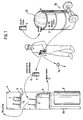
- waste oil cans 1 are collected in a barrel 2, which, for. B. get the customers at gas stations, and such collected waste oil cans are deburred using a deburring pliers 3, after which the waste oil can has a smooth opening edge 6 and is considered prepared.
- the prepared waste oil cans 1 are placed in an oil drip box 4, which has slanted drip trays 5 with which the opening edge 6 of the prepared waste can in Is brought into contact.
- the cans 1 are slightly inclined on the draining plates 5.
- This edge contact creates a continuous surface between the draining surface 5 and the interior of the prepared waste can, so that the surface tension of the remaining fresh oil in the can does not prevent the fresh oil from being completely removed from the can to drain.
- This remaining fresh oil flows along the drip tray 5 into a channel 7 and can be collected in a vessel 8.
- a barrel 9 can be placed below an oil drain screw on the oil drip box 4 to collect the oil.
- the draining time of the prepared waste oil cans 1 in the drainer 4 can be selected to be very long, for example over a day, practically no residual oil is found in the waste oil cans, and plastic material can be obtained again from the waste oil cans (recycling).
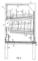
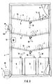
- FIGS. 1 and 3 show the oil drip box 4 from the front and from the side, respectively, in FIG. 2 the door 11 being largely broken away to reveal the view inside the box.
- Rails 13 are attached to the rear wall 12, with a certain slope, as can be seen.
- the drains 5 made of sheet metal are suspended in these rails and also have a certain slope to the front, as shown in FIGS. 1 and 3.
- a number of pins 14 are attached to the drains 5, the length of which is selected to match the size of the waste oil cans to be completely emptied.
- the waste oil cans 1 must rest on one side with their edge 6 on the surface of the drainer 5, which is why the pins 14 must not be too long, while on the other hand the waste oil cans 1 should be prevented from falling over.
- the wall bottom 15 of the oil drip box 4 is inclined and leads to an oil drain screw 16, which can also be arranged differently from FIG. 2 below the oil box 4.
- a grate can be 17 can be arranged, on which the oil collecting vessels 8 can be placed, as shown.
- the upper drip tray 5 is inclined to the left in the drawing, so that the recovered oil collects in the left vessel 8, while the lower drip tray 5 is inclined to the right, with the result that the recovered fresh oil is found in the right vessel 8.
- the rear wall 12 is retracted at its upper end and forms a rear gripping strip 18, so that the oil drip box can be hung on a wall.
- a base frame 19 it is also possible to provide a base frame 19 in order to mount the oil drain box 4 in a free-standing manner.
- FIG. 4 shows an enlarged detail Z from FIG. 3.
- the pin 14 can consist of a screw bolt 21 and a tightly wound coil spring 22 which is attached to the upper end of the screw bolt 21 and optionally also soldered on.
- the fastening in a hole in the sheet metal 5 takes place via two nuts 23 which clamp the edge of the hole.
- the coil spring 22 can be easily shortened if necessary so that the appropriate length of the pin 14 can be adapted to the requirements.
- the deburring pliers 3 are shown, with which the waste oil can can be prepared in such a way that the opening edge becomes burr-free in order to enable the fresh oil to be completely emptied.
- the deburring pliers have two legs 31, 32 which are connected to one another via an axle rivet 33 and can be pivoted against one another in order to widen and close the jaws 30.
- the pliers have handles 34.
- the legs 31, 32 each curve around the pliers mouth 30, in which the neck of the waste oil can is to be grasped.
- the legs 31 and 32 have respective guide edges 35 and 36 which are to be placed on the opening edge of the waste oil can from above.
- Arc-shaped extend parallel to the guide edges 35, 36 Retaining tabs 37, 38, on which cutting blades 39, 40 are attached, the cutting edges being opposed and projecting into the pliers mouth 30.
- the front end of the deburring pliers can also be designed as scissors 41.
- the pliers jaw 30 takes on a shape which matches the neck of the oil can, and the support edges 35, 36 form a guide for the upper edge of the oil can so that it can be rotated.
- the cutting edges of the blades 39, 40 come into engagement with the neck of the oil can, and by rotating the pliers relative to the oil can, a neck ring 1 a can be separated off, so that the prepared waste oil can is obtained, which has a burr-free edge 6 .
- the blades 39, 40 are fastened interchangeably, for example screwed on, and can be exchanged for new blades if required.
- the area 42 between the legs 31, 32 can also be designed with notched, curved edges, in order to be able to grip screw closures better.
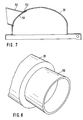
- FIG. 7 and 8 show a curved barrel lid 20 which is provided with a tubular insertion channel 50 for waste oil cans.
- the insertion channel 50 is long enough and approximately horizontally arranged to shield rain from its interior. For this reason, the front edge of the insertion channel 50 is slightly overhanging and sloping.
- the curved barrel cover 20 has a circular cutout in the region of the insertion channel 50, and this circular cutout is covered by a rubber flap 51 which is fastened at 52 inside the barrel cover 20.
- the rubber material of the flap 51 is sufficiently flexible so that waste oil cans can be pushed into the interior of the barrel lid 20 and resilient enough to cover and close the cut-out opening.
- the barrel lid 20 is attached to the barrel 2 with a clamping ring, not shown, which, moreover, with a transport cart 70 can be moved. (Further details are disclosed in applicant's EP 88 106 176.6.)
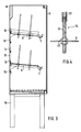
- FIG. 9 shows a second embodiment of the oil drip box 4 with the door 11 largely broken away, the same reference numerals being used as in the first embodiment according to FIGS. 2 and 3.
- the oil drip box is intended to be placed on the floor, and there are three drip trays 5 and space for three vessels 8 which are connected to the deepest points of the trays 5 via respective hose lines 10.
- the bottoms 5 are slightly inclined towards the center and towards the front in order to open into a channel 7, as is similarly shown in FIG. 3.
- a device 60 for making an opening with an outlet rim 6 on a bottle or can 1 is provided on the drainer according to FIG. 9.
- the device 60 comprises a foot lever 61, as shown in more detail in FIG. 10, and an actuating device 62 for a beak-like tool 63 (FIG. 11).
- the actuating device 62 has a working cylinder 64 with a piston rod 65 and two interconnected double-armed levers 66 and 67, which are each pivotably mounted at 68 and 69 and coupled to one another at 71.
- the piston rod 65 is coupled to the lever 66 at 72. Accordingly, when the working cylinder 64 makes a working stroke, the lever 66 in FIG.
- the contact jaws 73 serve to support a bottle or can 1 into which an opening with an outlet edge 6 is to be torn.
- the tool 63 has a certain resemblance to the beak of a bird of prey, ie the cutting edges are arcuate and meet at an acute angle in a tip which first penetrates the wall of the bottle or can 1. In the illustrated embodiment, this is a Can jacket from which a triangular piece is cut. It is important, however, that the bottom of the can 1 is cut through from above by the tool 63, so that the edge of the outlet opening formed is provided with a ridge which forms a good drip edge.
- an edge formed in this way is referred to as an outlet edge.
- a barrier edge In the usual way of opening cans, a barrier edge has always been created, which is why the cans cannot be completely emptied.
- the new way of creating the opening with burrs pointing outwards enables complete emptying of cans.
- the device 60 for attaching an outlet opening can be operated pneumatically, hydraulically or electrically, but also with foot power.
- a cap 74 is pivoted over the tool 63 and the lever 67 is secured by means of a bolt 75.
- Fig. 12 shows that in addition to the pin 14, a further pin 76 can be provided, which is provided with a tip.
- the outlet edge 6 should touch the respective inclined floor 5. So that this is retained, a certain fixation of the can or bottle 1 is desirable, which is done with the aid of the pin 76.
- the pin 14 can also be fir-tree shaped, namely slimmer (Fig. 13) or wider (Fig. 14) in order to support different types of bottles and cans in a suitable manner.
Landscapes
- Engineering & Computer Science (AREA)
- Mechanical Engineering (AREA)
- Processing Of Solid Wastes (AREA)
- Devices For Opening Bottles Or Cans (AREA)
- Lubrication Details And Ventilation Of Internal Combustion Engines (AREA)
- Discharge Of Articles From Conveyors (AREA)
- Control And Other Processes For Unpacking Of Materials (AREA)
- Loading And Unloading Of Fuel Tanks Or Ships (AREA)
Abstract
Description
Die Erfindung bezieht sich auf ein Verfahren zur weitestgehenden Entleerung von Flaschen oder Dosen, auf eine Vorrichtung zur Entleerung von Flaschen oder Dosen, auf eine Entgratungszange zum Präparieren des Auslaufrandes von Kunststoffflaschen und -dosen, auf eine Vorrichtung zum Präparieren des Auslaufrandes von Flaschen oder Dosen sowie auf eine Sammelvorrichtung bei der Durchführung des Verfahrens.The invention relates to a method for largely emptying bottles or cans, to a device for emptying bottles or cans, to a deburring pliers for preparing the outlet rim of plastic bottles and cans, to a device for preparing the outlet rim of bottles or cans and on a collecting device when carrying out the method.
Öldosen werden üblicherweise mit einem Dorn geöffnet, der Durchstoßöffnungen mit nach innen reichenden Graten am Öldosenboden bildet. Bei einer bekannten Vorrichtung zur Nachentleerung von so geöffneten Dosen (US-A-2 199 970) ist ein Abtropfkasten mit oberseitiger Klappe vorgesehen, die Zugang zu einer schräg angeordneten Platte gewährt, die mit einer Vielzahl von Öffnungen versehen ist. Der jeweilige Öffnungsrand ist mit einem Kranz nach unten reichender Drähte versehen, die entlang eines konischen Mantels angeordnet sind. Geöffnete Öldosen mit einem Restinhalt können schräg nach unten in die Plattenöffnungen und die Drahtkränze gehängt werden, und abtropfendes Öl wird auf einem Boden aufgefangen und in einem Auffanggefäß gesammelt. Da die Durchstoßöffnungen im Öldosenboden praktisch niemals am Dosenmantel angeordnet sind, verbleibt in der Öldose ein toter Winkel, aus dem das Restöl bei schräger Stellung der Dose nicht auslaufen kann. Deshalb und wegen der nach innen gerichteten Grate an den Durchstoßöffnungen ist eine restlose Entleerung der Dosen nicht möglich.Oil cans are usually opened with a mandrel that forms penetration openings with inwardly extending ridges on the bottom of the oil can. In a known device for the subsequent emptying of cans opened in this way (US-A-2 199 970), a drainer with a top flap is provided, which gives access to an obliquely arranged plate which is provided with a multiplicity of openings. The respective edge of the opening is provided with a ring of wires extending downwards, which are arranged along a conical jacket. Opened oil cans with residual contents can be hung diagonally down into the plate openings and the wire wreaths, and dripping oil is collected on a floor and collected in a collecting vessel. Since the penetration openings in the bottom of the oil can are practically never arranged on the can jacket, a dead angle remains in the oil can, from which the residual oil cannot run out when the can is at an angle. Because of this and because of the inward burrs at the through openings, a complete emptying of the cans is not possible.
Bei der Entsorgung von Abfallöldosen ist es lästig, daß in diesen Abfalldosen noch eine Restmenge an Frischöl haftet. Im Falle von Flaschen oder Dosen aus Kunststoff könnte das Wandmaterial wiederverwendet (recycled) werden, wenn die Beseitigung des Restöls gelänge.When disposing of waste oil cans, it is troublesome that a residual amount of fresh oil still adheres to these waste cans. In the case of bottles or cans made of plastic, the wall material could be reused (recycled) if the residual oil could be removed.
Die Aufgabe, Dosen und Flaschen weitgehend zu entleeren, wird durch die kennzeichnenden Merkmale der Ansprüche 1 und 3 gelöst.The task of largely emptying cans and bottles is solved by the characterizing features of
Der mit dem erfindungsgemäßen Verfahren gewonnene Restinhalt der Flaschen oder Dosen kann einer sinnvollen Verwendung zugeführt werden. Die Dosen oder Flaschen sind nach der erfindungsgemäßen Behandlung soweit vorgereinigt, daß das Material dieser Dosen oder Flaschen einer Wieder verwendung zugeführt werden kann.The residual content of the bottles or cans obtained with the method according to the invention can be put to a reasonable use. After the treatment according to the invention, the cans or bottles are pre-cleaned to such an extent that the material of these cans or bottles can be reused.
Das Entleerungsverfahren kann insbesondere auf Motoröl angewendet werden, dessen Haftfähigkeit besonders groß ist, so daß sich in an sich entleerten Dosen oder Flaschen größere Restmengen an solchem Motoröl finden und die Ausbeute mit dem erfindungsgemäßen System lohnend wird. Das Material der entleerten Dosen oder Flaschen wird dem Recycling zugeführt.The emptying process can be applied in particular to motor oil, the adhesiveness of which is particularly high, so that larger amounts of such motor oil can be found in cans or bottles which are emptied per se and the yield with the system according to the invention becomes profitable. The material of the emptied cans or bottles is sent for recycling.
Gerätemäßig weist das erfindungsgemäße System einen Abtropfkasten auf, der geneigte Abtropfböden oder -bleche aufweist. Zur Anpassung an unterschiedliche Größen der Dosen oder Flaschen können diese Abtropfböden oder -bleche umgehängt werden, weswegen Führungen an der Rückwand des Kastens vorgesehen sind, in welche diese Abtropfbleche eingehängt sind. Die Abtropfböden oder -bleche sind an ihrem vorderen Rand im Sinne einer Rinne ausgebildet. Auf diese Weise kann die gewonnene Flüssigkeit unmittelbar in Auffanggefäße geleitet werden. Es ist aber auch möglich, die wiedergewonnene Flüssigkeit im unteren Teil des Abtropfkastens zu sammeln und über eine Ablaßschraube oder dergleichen in ein Auffanggefäß abzulassen.In terms of equipment, the system according to the invention has a drip tray which has inclined drip trays or trays. To adapt to different sizes of cans or bottles, these draining trays or trays can be moved around, which is why guides are provided on the rear wall of the box, into which these draining trays are suspended. The draining trays or trays are designed in the form of a gutter at their front edge. In this way, the liquid obtained can be passed directly into collecting vessels. However, it is also possible to collect the recovered liquid in the lower part of the drip box and to drain it into a collecting vessel via a drain screw or the like.
Zum gekippten Halten der Flaschen oder Dosen weisen die Abtropfböden Halter z. B. in Form von Stiften auf. Die Länge der Stifte oberhalb der Abtropfböden kann verändert werden, sei es, daß die Stifte gekürzt werden, sei es, daß diese weiter in die Ebene des Abtropfbodens hineingeschraubt werden. Die Halter können einen tannenbaumartigen Querschnitt aufweisen.To hold the bottles or cans tilted, the drainer holders have e.g. B. in the form of pens. The length of the pins above the drains can be changed, either by shortening the pins or by screwing them further into the plane of the drains. The holders can have a fir tree-like cross section.
Zur weitgehend restlosen Entleerung von Dosen für Motoröl kann der Halsrand der Abfalldosen gratfrei abgeschnitten werden. Zu diesem Zweck ist eine spezielle Entgratungszange vorgesehen, welche den Öffnungsrand von Kunststoffdosen gratfrei zu machen ermöglicht. Es kann aber auch eine Vorrichtung zum Anbringen einer Auslauföffnung mit Auslaufrand an einer Flasche oder Dose vorgesehen sein, die ein hobelartiges oder Raubvogelschnabel-artiges Werkzeug aufweist, das die Auslauföffnung vom Inneren der Dose oder Flasche schneidet, so daß der Öffnungsrand mit nach außen gerichteten Graten versehen ist, welche den Auslauf auch von zäher Flüssigkeit begünstigen. Bei solchen präparierten Dosen wird eine restlose Entleerung erzielt, d. h. die Restmenge ist weniger als ein Tropfen Motoröl.The neck rim of the waste cans can be trimmed free of burrs to completely empty cans for motor oil. To For this purpose, special deburring pliers are provided, which make the opening edge of plastic cans free of burrs. But it can also be provided a device for attaching an outlet opening with an outlet rim to a bottle or can, which has a planer-like or bird of prey-like tool that cuts the outlet opening from the inside of the can or bottle, so that the opening edge with burrs pointing outwards is provided, which also favor the discharge of viscous liquid. With such prepared cans, complete emptying is achieved, ie the remaining amount is less than a drop of engine oil.
Das Gesamtsystem umfaßt auch ein Sammelgefäß für die zu entleerenden Flaschen oder Dosen mit Restinhalt. Zum Schutz gegen eindringendes Wasser, welches das wiederzugewinnende Motorfrischöl verderben könnte, ist ein gewölbter Deckel mit Einwurfkanal für das Sammelgefäß vorgesehen. Der Einwurfkanal ist als Schutz gegen eindringendes Regenwasser ausgebildet, und eine Klappe durch die Durchbruchsöffnung durch den Deckel sorgt dafür, daß auch der Vorraum zum Sammelgefäß windgeschützt ist.The overall system also includes a collecting vessel for the bottles or cans with residual contents to be emptied. To protect against the ingress of water, which could spoil the fresh engine oil to be recovered, a domed lid with a feed channel is provided for the collecting vessel. The throw-in channel is designed as protection against the ingress of rainwater, and a flap through the opening through the lid ensures that the anteroom to the collecting vessel is also protected from the wind.
Die Erfindung wird anhand der Zeichnung besprochen. Dabei zeigt:
- Fig. 1
- das Gesamtsystem in schematischer Darstellung,
- Fig. 2
- einen Ölabtropfkasten, teilweise aufgeschnitten,
- Fig. 3
- den Ölabtropfkasten, von der Seite gesehen, im Schnitt,
- Fig. 4
- eine vergrößerte Einzelheit aus Fig. 3,
- Fig. 5
- eine Entgratzange, von der Seite gesehen,
- Fig. 6
- die Entgratzange im Draufblick,
- Fig. 7
- einen Faßdeckel mit Einwurfkanal und
- Fig. 8
- den Einwurfkanal in perspektivischer Darstellung,
- Fig. 9
- eine zweite Ausführungsform des Ölabtropfkastens,
- Fig. 10
- eine Einzelheit V in vergrößerter Darstellung aus Fig. 9,
- Fig. 11
- eine Einzelheit W in vergrößerter Darstellung aus Fig. 9,
- Fig. 12
- eine Einzelheit X in vergrößerter Darstellung aus Fig. 9,
- Fig. 13
- eine Einzelheit Y in vergrößerter Darstellung aus Fig. 9 und
- Fig. 14
- eine Einzelheit Z in vergrößerter Darstellung aus Fig. 9.
- Fig. 1
- the overall system in a schematic representation,
- Fig. 2
- an oil drainer, partially cut open,
- Fig. 3
- the oil drain box, seen from the side, in section,
- Fig. 4
- 3 shows an enlarged detail from FIG. 3,
- Fig. 5
- a deburring tool, seen from the side,
- Fig. 6
- the deburring pliers at a glance,
- Fig. 7
- a barrel lid with a slot and
- Fig. 8
- the insertion channel in perspective,
- Fig. 9
- a second embodiment of the Oil drain box,
- Fig. 10
- a detail V in an enlarged view of FIG. 9,
- Fig. 11
- 4 shows a detail W in an enlarged illustration from FIG. 9,
- Fig. 12
- 4 shows a detail X in an enlarged representation from FIG. 9,
- Fig. 13
- a detail Y in an enlarged view of Fig. 9 and
- Fig. 14
- a detail Z in an enlarged view from FIG. 9.
Wenn Autofahrer Motoröl nachfüllen, fällt eine Abfallöldose an, in der gewöhnlich noch eine Menge Frischöl haftet, welches bisher verloren geht. Öldosen sind gewöhnlich aus Kunststoff und haben eine angenäherte Flaschenform, wobei die Halsöffnung mit einer Membran verschlossen ist, die zur Entnahme des Frischöls durchstoßen werden muß. Wegen dieser Membran, die einen Grat bildet, kann sich die Öldose nicht völlig entleeren, auch wenn der Autofahrer die Öldose sehr lange an den Öleinfüllstutzen seines Motors hält. Die mangelnde Entleerung der Motoröldose ist nicht nur wegen des Verlustes an Frischöl bedauernswert, sondern auch im Hinblick auf Recycling des Kunststoffmaterials der Öldose schädlich.When drivers refill motor oil, a waste oil can is produced, in which there is usually still a lot of fresh oil that has been lost so far. Oil cans are usually made of plastic and have an approximate bottle shape, the neck opening being closed with a membrane which has to be pierced in order to remove the fresh oil. Because of this membrane, which forms a ridge, the oil can cannot empty completely, even if the driver holds the oil can for a very long time on the oil filler neck of his engine. The lack of emptying of the motor oil can is unfortunate not only because of the loss of fresh oil, but also with regard to recycling the plastic material of the oil can.
Mit dem erfindungsgemäßen System soll das restliche Frischöl in der Abfallöldose wiedergewonnen werden, und es soll diese Abfallöldose für das Recycling des Kunststoffmaterials vorbereitet werden. Wie aus Fig. 1 ersichtlich, werden Abfallöldosen 1 in einem Faß 2 gesammelt, was z. B. die Kunden an Tankstellen besorgen, und solche gesammelten Abfallöldosen werden mittels einer Entgratungszange 3 entgratet, wonach die Abfallöldose einen glatten Öffnungsrand 6 aufweist und als präpariert gilt. Die präparierten Abfallöldosen 1 werden in einen Ölabtropfkasten 4 gesteckt, welcher schräg angeordnete Abtropfböden 5 aufweist, mit denen der Öffnungsrand 6 der präparierten Abfalldose in Berührung gebracht wird. Die Dosen 1 stehen ein wenig schräg auf den Abtropfböden 5. Durch diese Kantenberührung kommt eine durchgehende Oberfläche zwischen Abtropffläche 5 und dem Inneren der präparierten Abfalldose zustande, so daß die Oberflächenspannung des restlichen Frischöls in der Dose das Frischöl nicht daran hindert, restlos aus der Dose abzufließen. Dieses restliche Frischöl fließt entlang dem Abtropfboden 5 in eine Rinne 7 und kann in einem Gefäß 8 aufgefangen werden. Alternativ kann ein Faß 9 unterhalb einer Ölablaßschraube am Ölabtropfkasten 4 aufgestellt werden, um das Öl aufzufangen.With the system according to the invention, the remaining fresh oil is to be recovered in the waste oil can, and this waste oil can is to be prepared for the recycling of the plastic material. As can be seen from Fig. 1, waste oil cans 1 are collected in a
Da die Abtropfzeit der präparierten Abfallöldosen 1 in dem Abtropfkasten 4 sehr lang, beispielsweise über einen Tag, gewählt werden kann, wird praktisch kein Restöl in den Abfallöldosen angetroffen, und aus den Abfallöldosen kann erneut Kunststoffmaterial gewonnen werden (Recycling).Since the draining time of the prepared waste oil cans 1 in the drainer 4 can be selected to be very long, for example over a day, practically no residual oil is found in the waste oil cans, and plastic material can be obtained again from the waste oil cans (recycling).
Fig. 2 und 3 zeigen den Ölabtropfkasten 4 von vorne bzw. der Seite, wobei in Fig. 2 die Tür 11 größtenteils weggebrochen ist, um den Blick ins Innere des Kastens freizugeben. An der Rückwand 12 sind Schienen 13 angebracht, und zwar mit einem gewissen Gefälle, wie ersichtlich. In diese Schienen sind die aus Blech gefertigten Abtropfböden 5 eingehängt, welche außerdem ein gewisses Gefälle nach vorne aufweisen, wie in den Fig. 1 und 3 dargestellt. Auf den Abtropfböden 5 ist eine Reihe von Stiften 14 angebracht, deren Länge passend zur Größe der restlos zu entleerenden Abfallöldosen gewählt ist. Wie bereits erwähnt, müssen die Abfallöldosen 1 mit ihrem Rand 6 auf der Oberfläche des Abtropfbodens 5 einseitig aufliegen, weswegen die Stifte 14 nicht allzu lang sein dürfen, während andererseits ein Herumfallen der Abfallöldosen 1 verhindert werden soll.2 and 3 show the oil drip box 4 from the front and from the side, respectively, in FIG. 2 the
Der Wandboden 15 des Ölabtropfkastens 4 ist geneigt und führt zu einer Ölablaßschraube 16, die im übrigen auch abweichend von Fig. 2 unterhalb des Ölkastens 4 angeordnet sein kann. Oberhalb des geneigten Wandbodens 15 kann ein Rost 17 angeordnet sein, auf den die Ölauffanggefäße 8 gestellt werden können, wie dargestellt. Das obere Abtropfblech 5 ist in der Zeichnung nach links geneigt, so daß sich das wiedergewonnene Öl im linken Gefäß 8 sammelt, während das untere Abtropfblech 5 nach rechts geneigt ist mit der Folge, daß sich im rechten Gefäß 8 das wiedergewonnene Frischöl wiederfindet.The
Wie aus Fig. 3 hervorgeht, ist die Rückwand 12 an ihrem oberen Ende eingezogen und bildet eine Hintergreifleiste 18, so daß der Ölabtropfkasten an einer Wand aufgehängt werden kann. Es ist aber auch möglich, ein Fußgestell 19 vorzusehen, um den Ölabtropfkasten 4 freistehend zu montieren.As is apparent from Fig. 3, the
Fig. 4 zeigt eine vergrößerte Einzelheit Z aus Fig. 3. Wie ersichtlich, kann der Stift 14 aus einem Schraubbolzen 21 und einer eng gewickelten Schraubenfeder 22 bestehen, die auf das obere Ende des Schraubbolzens 21 aufgesteckt und gegebenenfalls auch angelötet ist. Die Befestigung in einer Bohrung im Blech 5 erfolgt über zwei Muttern 23, die den Bohrungsrand einklemmen. Die Schraubfeder 22 kann bei Bedarf leicht gekürzt werden, so daß die passende Länge des Stiftes 14 den Erfordernissen angepaßt werden kann.FIG. 4 shows an enlarged detail Z from FIG. 3. As can be seen, the
In den Fig. 5 und 6 ist die Entgratungszange 3 gezeigt, mit der die Abfallöldose so präpariert werden kann, daß der Öffnungsrand gratlos wird, um die restlose Entleerung des Frischöls zu ermöglichen. Die Entgratungszange besitzt zwei Schenkel 31, 32, die über einen Achsniet 33 miteinander verbunden sind und gegeneinander geschwenkt werden können, um das Zangenmaul 30 zu erweitern und zu schließen. Zur bequemeren Handhabung besitzt die Zange Griffe 34. Die Schenkel 31, 32 machen jeweils einen Bogen um das Zangenmaul 30 herum, in welchem der Hals der Abfallöldose zu erfassen ist. Zu diesem Zweck weisen die Schenkel 31 und 32 jeweilige Führungsränder 35 und 36 auf, die von oben her auf den Öffnungsrand der Abfallöldose zu legen sind. Parallel zu den Führungsrändern 35, 36 erstrecken sich bogenförmige Haltelappen 37, 38, an denen Schneidklingen 39, 40 befestigt sind, wobei sich die Schneiden gegenüberstehen und in das Zangenmaul 30 hineinragen. Das vordere Ende der Entgratungszange kann noch als Schere 41 ausgebildet sein.5 and 6, the
Wenn die Entgratungszange 3 geöffnet wird, nimmt das Zangenmaul 30 eine Form passend zum Hals der Öldose an, und die Auflageränder 35, 36 bilden eine Führung für den oberen Rand der Öldose, so daß diese gedreht werden kann. Durch entsprechendes Schließen der Zange kommen die Schneiden der Klingen 39, 40 mit dem Hals der Öldose in Eingriff, und durch Drehen der Zange relativ zur Öldose kann ein Halsring 1a abgetrennt werden, so daß die präparierte Abfallöldose erhalten wird, welche einen gratfreien Rand 6 besitzt.When the
Die Klingen 39, 40 sind austauschbar befestigt, beispielsweise angeschraubt, und können gegen neue Klingen ausgetauscht werden, falls benötigt. Der Bereich 42 zwischen den Schenkeln 31, 32 kann im übrigen auch mit gekerbten, gebogenen Rändern gestaltet sein, um Schraubverschlüsse besser greifen zu können.The
Fig. 7 und 8 zeigen einen gewölbten Faßdeckel 20, der mit einem rohrförmigen Einwurfkanal 50 für Abfallöldosen versehen ist. Der Einwurfkanal 50 ist genügend lang und etwa horizontal angeordnet, um Regen von seinem Inneren abzuschirmen. Deswegen ist der vordere Rand des Einwurfkanals 50 leicht überhängend-schräg gestaltet. Der gewölbte Faßdeckel 20 weist einen kreisförmigen Ausschnitt im Bereich des Einwurfkanals 50 auf, und dieser kreisförmige Ausschnitt wird von einer Gummiklappe 51 abgedeckt, die im Inneren des Faßdeckels 20 bei 52 befestigt ist. Das Gummimaterial der Klappe 51 ist genügend nachgiebig, so daß Abfallöldosen in das Rauminnere des Faßdeckels 20 geschoben werden können, und genügend elastisch rückfedernd, um die ausgeschnittene Öffnung abzudecken und zu verschließen.7 and 8 show a
Der Faßdeckel 20 ist mit einem nicht dargestellten Spannring auf dem Faß 2 befestigt, welches im übrigen mit einer Transportkarre 70 verfahren werden kann. (Nähere Einzelheiten sind in EP 88 106 176.6 des Anmelders offenbart.)The
Fig. 9 zeigt eine zweite Ausführungsform des Ölabtropfkastens 4 bei größtenteils weggebrochener Tür 11, wobei die gleichen Bezugszeichen wie bei der ersten Ausführungsform nach Fig. 2 und 3 benutzt werden. Der Ölabtropfkasten ist zum Aufstellen auf dem Boden gedacht, und es sind drei Abtropfböden 5 sowie Raum für drei Gefäße 8 vorgesehen, die über jeweilige Schlauchleitungen 10 mit den tiefsten Stellen der Böden 5 verbunden sind. Die Böden 5 sind nach der Mitte zu und nach vorne hin leicht geneigt, um in eine Rinne 7 einzumünden, wie diese ähnlich in Fig. 3 dargestellt ist.FIG. 9 shows a second embodiment of the oil drip box 4 with the
An dem Abtropfkasten nach Fig. 9 ist eine Vorrichtung 60 zum Anbringen einer Öffnung mit Auslaufrand 6 an einer Flasche oder Dose 1 vorgesehen. Die Vorrichtung 60 umfaßt einen Fußhebel 61, wie er in Fig. 10 näher dargestellt ist, und eine Betätigungseinrichtung 62 für ein schnabelartiges Werkzeug 63 (Fig. 11). Die Betätigungseinrichtung 62 weist einen Arbeitszylinder 64 mit Kolbenstange 65 und zwei miteinander verbundene doppelarmige Hebel 66 und 67 auf, die bei 68 und 69 jeweils schwenkbar gelagert und bei 71 miteinander gekoppelt sind. Die Kolbenstange 65 ist mit dem Hebel 66 bei 72 gekoppelt. Wenn demnach der Arbeitszylinder 64 einen Arbeitshub macht, wird der Hebel 66 in Fig. 2 entgegen dem Uhrzeigersinn und der Hebel 67 im Uhrzeigersinn geschwenkt, wobei sich das Werkzeug 63 in einen Raum zwischen zwei Anlagebacken 73 bewegt. Die Anlagebacken 73 dienen zur Aufstützung einer Flasche oder Dose 1, in die eine Öffnung mit Auslaufrand 6 gerissen werden soll. Das Werkzeug 63 hat eine gewisse Ähnlichkeit mit dem Schnabel eines Greifvogels, d. h. die schneidenden Ränder sind bogenförmig und treffen sich im spitzen Winkel in einer Spitze, die als erstes in die Wandung der Flasche oder Dose 1 eindringt. Im dargestellten Ausführungsbeispiel ist dies ein Dosenmantel, aus dem ein dreieckförmiges Stück geschnitten wird. Wichtig ist jedoch, daß der Boden der Dose 1 durch das Werkzeug 63 von oben her durchtrennt wird, so daß der Rand der gebildeten Auslaßöffnung mit einem Grat nach unten versehen wird, der eine gute Abtropfkante bildet. Ein so ausgebildeter Rand wird als Auslaufrand bezeichnet. Wenn demgegenüber die Öffnung so gebildet wird, daß der Grat ins Doseninnere weist, wird ein solcher Öffnungsrand als Sperrand bezeichnet. Bei der bisher üblichen Art der Öffnung von Dosen ist immer ein Sperrand erzeugt worden, weswegen sich eben die Dosen nicht vollständig leeren lassen. Durch die neue Art der Erzeugung der Öffnung mit nach außen gerichteten Graten ist dagegen eine vollständige Entleerung von Dosen möglich.A
Die Vorrichtung 60 zum Anbringen einer Auslauföffnung kann pneumatisch, hydraulisch oder elektrisch, aber auch mit Fußkraft betrieben werden. In der Ruhestellung des Geräts wird eine Kappe 74 über das Werkzeug 63 geschwenkt, und der Hebel 67 wird mittels eines Riegels 75 gesichert.The
Fig. 12 zeigt, daß neben dem Stift 14 noch ein weiterer Stift 76 vorgesehen sein kann, der mit einer Spitze versehen ist. Um Flaschen oder Dosen 1 restlos zu entleeren, sollte nämlich der Auslaufrand 6 den jeweiligen geneigten Boden 5 berühren. Damit dies beibehalten bleibt, ist eine gewisse Fixierung der Dose oder Flasche 1 wünschenswert, was mit Hilfe des Stiftes 76 geschieht.Fig. 12 shows that in addition to the
Wie die Fig. 13 und 14 zeigen, kann der Stift 14 auch tannenbaumartig gestaltet sein, und zwar schlanker (Fig. 13) oder breiter (Fig. 14), um unterschiedliche Arten von Flaschen und Dosen in geeigneter Weise zu stützen.As shown in Figs. 13 and 14, the
Claims (12)
- A method for extensively clearing of tins or bottles comprising the following steps:
collecting bottles or tins (1) having remnants of liquid;
preparing the collected bottles or tins (1) in respect to a draining rim (6) which is either free of burrs or has a burr in draining direction;
positioning the draining rim (6) of the prepared bottles or tins (1) onto a respective base (5) of a drip box (4) in a slightly tilted manner so as to create a liquid film which is uninterrupted between the interior of the bottle or tin (1) and the surface of the base (5);
causing the remnant liquid to flow out over the draining rim (6) during a sufficient duration of time and passing same into a collecting vessel (8, 9);
drawing the bottles or tins (1) from the drip box (4) for being devoted to further use; and
devoting the remnant liquid collected in the collection vessel (8, 9) to the provided use. - The method of claim 1
wherein the liquid is motor oil. - A device for depleting bottles or tins, comprising
a drip box (4),
a base (5) for collecting remnant liquid and
a collecting vessel (8, 9),
characterized in that
the base (5) of the device comprises a supporting means (14) adapted to hold the bottles or tins (1) having a draining rim (6) prepared by deflashing nippers so that these bottles or tins stand tilted on the base, providing an uninterrupted surface between the interior of the bottle or tin (1) and the base (5) so that the liquid can flow out essentially completely. - The device according to claim 3,
wherein a holding means (76) is assigned to the supporting means (14), the holding means holding the bottles or tins (1) in a tilted condition on the basis (5). - The device according to claim 3
wherein the supporting means (14) is configured firtree-like. - The device according to one of the claims 3 through 5, wherein the drip box (4) comprises a door (11) on the frontside providing access to at least two bottoms (5) arranged one above the other and wherein a rear wall (12) comprises fixing means (13) for the bottoms (5) being arranged one above the other.
- A device according to one of the claims 3 through 6 wherein each bottom (5) has a forward rim which is configured as a channel (7).
- Deflashing nippers for preparing the draining rim of bottles or tins made of plastics according to claims 1 or 3,
wherein the deflashing nippers (3) comprise leading rims (35, 36) for positioning the opening of the bottle or tin thereonto and
wherein cutting knives (39, 40) are arranged in a distance parallel to the leading rims (34, 36), the cutting knives extending into a cylindric mouth (30) of the nippers when the same is opened and being able to cut an annular rim (1a) from the bottle or tin. - Cutting device for preparing the draining rim of bottles or tins according to claims 1 or 3,
wherein a drive means (62) and a driven tool (63) which is plane-like or beak-like are provided to cut through the bottom of the bottle or tin (1) from above and with a flash directed downwardly. - Cutting device according to claim 9,
wherein a pair of engagement surfaces (73) are provided for the bottom wall of the bottle or tin (1), a clearance space being left therebetween to take up the tool (63) which may enter therein after having cut through the bottom wall of the bottle or tin (1) from the inside. - Collecting device useful for carrying out the method according to one of the claims 1 or 2,
wherein a collecting vessel (2) for bottles or tins with remnants is provided which comprises a concave lid (20) and an input channel (50). - Collecting device according to claim 11,
wherein the input passage (50) is configured as a protection against rainwater and
wherein a flapper (51) shuts the entering opening through the lid (20).
Priority Applications (1)
| Application Number | Priority Date | Filing Date | Title |
|---|---|---|---|
| AT89116510T ATE101583T1 (en) | 1988-09-13 | 1989-09-07 | DEVICE AND METHOD FOR THE COMPLETE EMPTYING OF CANS AND BOTTLES. |
Applications Claiming Priority (2)
| Application Number | Priority Date | Filing Date | Title |
|---|---|---|---|
| DE3831154 | 1988-09-13 | ||
| DE19883831154 DE3831154A1 (en) | 1988-09-13 | 1988-09-13 | SYSTEM FOR COMPLETELY EMPTYING CAN AND BOTTLES |
Publications (2)
| Publication Number | Publication Date |
|---|---|
| EP0359115A1 EP0359115A1 (en) | 1990-03-21 |
| EP0359115B1 true EP0359115B1 (en) | 1994-02-16 |
Family
ID=6362885
Family Applications (1)
| Application Number | Title | Priority Date | Filing Date |
|---|---|---|---|
| EP89116510A Expired - Lifetime EP0359115B1 (en) | 1988-09-13 | 1989-09-07 | Device and method for emptying tins and bottles without leaving a residue |
Country Status (3)
| Country | Link |
|---|---|
| EP (1) | EP0359115B1 (en) |
| AT (1) | ATE101583T1 (en) |
| DE (2) | DE3831154A1 (en) |
Cited By (1)
| Publication number | Priority date | Publication date | Assignee | Title |
|---|---|---|---|---|
| WO2024110003A1 (en) * | 2022-11-22 | 2024-05-30 | Knauf Gips Kg | Holder for fastening a load to a dry-construction structure, a kit and a dry-construction structure comprising such a holder, and a method of fastening loads to a dry-construction structure |
Families Citing this family (1)
| Publication number | Priority date | Publication date | Assignee | Title |
|---|---|---|---|---|
| AT411593B (en) * | 2002-05-16 | 2004-03-25 | Meier Erich | DEVICE FOR REMOVING LIQUID TANKS, ESPECIALLY FOR LUBRICATING OIL |
Family Cites Families (2)
| Publication number | Priority date | Publication date | Assignee | Title |
|---|---|---|---|---|
| US2199970A (en) * | 1938-06-22 | 1940-05-07 | Mitchell Metal Products Inc | Combination oil salvage and refuse container and display rack |
| CH287172A (en) * | 1950-10-18 | 1952-11-30 | Mercier Robert | Support for cans. |
-
1988
- 1988-09-13 DE DE19883831154 patent/DE3831154A1/en not_active Withdrawn
-
1989
- 1989-09-07 AT AT89116510T patent/ATE101583T1/en not_active IP Right Cessation
- 1989-09-07 EP EP89116510A patent/EP0359115B1/en not_active Expired - Lifetime
- 1989-09-07 DE DE89116510T patent/DE58906977D1/en not_active Expired - Fee Related
Cited By (1)
| Publication number | Priority date | Publication date | Assignee | Title |
|---|---|---|---|---|
| WO2024110003A1 (en) * | 2022-11-22 | 2024-05-30 | Knauf Gips Kg | Holder for fastening a load to a dry-construction structure, a kit and a dry-construction structure comprising such a holder, and a method of fastening loads to a dry-construction structure |
Also Published As
| Publication number | Publication date |
|---|---|
| EP0359115A1 (en) | 1990-03-21 |
| ATE101583T1 (en) | 1994-03-15 |
| DE3831154A1 (en) | 1990-03-22 |
| DE58906977D1 (en) | 1994-03-24 |
Similar Documents
| Publication | Publication Date | Title |
|---|---|---|
| DE19808903A1 (en) | Waste bin with slide-on lid | |
| DE2658432A1 (en) | METHOD AND DEVICE FOR ATTACHING CONTAINERS TO A FRAME AND CLOSING THEM | |
| DE19633038A1 (en) | Shears for objects made from slippery material | |
| EP0045378B1 (en) | Device for draining and collecting oil | |
| EP0401528A2 (en) | Support device for slaughtered poultry during treatment | |
| DE4024048C2 (en) | Beverage can press | |
| DE69509740T2 (en) | Automatic machine for taking back used cups | |
| EP0359115B1 (en) | Device and method for emptying tins and bottles without leaving a residue | |
| EP0702905A2 (en) | Process and apparatus for emptying a container | |
| DE69300074T2 (en) | Device for opening and emptying filled cans. | |
| DE4034639A1 (en) | Bottle carton partition deployment machine - has single pick=up head with intermittent drive from rotary motor | |
| DE20317895U1 (en) | Device for cleaning drinking vessels | |
| DE2659150A1 (en) | FITTED GUIDELINES FOR A STOP MACHINE | |
| DE4314729A1 (en) | Process and apparatus for cleaning the outer surface of (useful-material) collecting containers | |
| EP1390272B1 (en) | Holder for recycling bottles and recycling bottle | |
| DE69804819T2 (en) | Device for making a container open at one end from a can closed at both ends | |
| DE3403029A1 (en) | Device for the individual removal of rods of material from storage cartridges | |
| DE60225913T2 (en) | Device for the releasable fastening and holding of flexible and / or flat objects | |
| DE3515584A1 (en) | Recovery combination container | |
| DE102012103102A1 (en) | Waste container has pallet which is provided on upper edge of container wall to hold waste bag, and cover that is arranged on pallet and is moved relative to pallet | |
| DE1621874A1 (en) | Method and device for applying a plastic stain to mass-produced articles | |
| DE19509596A1 (en) | Disposable industrial plastic drum cleaning, disassembly and recycling or disposal process | |
| DE102021100633A1 (en) | UNPACKING A CONTAINER | |
| DE1918331U (en) | DEVICE FOR COLLECTING SUBSTANCES, IN PARTICULAR LIQUID SUBSTANCES. | |
| DE4013345A1 (en) | Connecting foil webs on packing machines - involves system for complete removal of seam overlaps |
Legal Events
| Date | Code | Title | Description |
|---|---|---|---|
| PUAI | Public reference made under article 153(3) epc to a published international application that has entered the european phase |
Free format text: ORIGINAL CODE: 0009012 |
|
| AK | Designated contracting states |
Kind code of ref document: A1 Designated state(s): AT BE CH DE ES FR GB GR IT LI LU NL SE |
|
| 17P | Request for examination filed |
Effective date: 19900908 |
|
| 17Q | First examination report despatched |
Effective date: 19920708 |
|
| GRAA | (expected) grant |
Free format text: ORIGINAL CODE: 0009210 |
|
| AK | Designated contracting states |
Kind code of ref document: B1 Designated state(s): AT BE CH DE ES FR GB GR IT LI LU NL SE |
|
| PG25 | Lapsed in a contracting state [announced via postgrant information from national office to epo] |
Ref country code: IT Free format text: LAPSE BECAUSE OF FAILURE TO SUBMIT A TRANSLATION OF THE DESCRIPTION OR TO PAY THE FEE WITHIN THE PRE;WARNING: LAPSES OF ITALIAN PATENTS WITH EFFECTIVE DATE BEFORE 2007 MAY HAVE OCCURRED AT ANY TIME BEFORE 2007. THE CORRECT EFFECTIVE DATE MAY BE DIFFERENT FROM THE ONE RECORDED.SCRIBED TIME-LIMIT Effective date: 19940216 Ref country code: BE Effective date: 19940216 Ref country code: GR Free format text: LAPSE BECAUSE OF FAILURE TO SUBMIT A TRANSLATION OF THE DESCRIPTION OR TO PAY THE FEE WITHIN THE PRESCRIBED TIME-LIMIT Effective date: 19940216 Ref country code: FR Free format text: THE PATENT HAS BEEN ANNULLED BY A DECISION OF A NATIONAL AUTHORITY Effective date: 19940216 Ref country code: SE Effective date: 19940216 Ref country code: NL Effective date: 19940216 Ref country code: ES Free format text: THE PATENT HAS BEEN ANNULLED BY A DECISION OF A NATIONAL AUTHORITY Effective date: 19940216 Ref country code: GB Effective date: 19940216 |
|
| REF | Corresponds to: |
Ref document number: 101583 Country of ref document: AT Date of ref document: 19940315 Kind code of ref document: T |
|
| REF | Corresponds to: |
Ref document number: 58906977 Country of ref document: DE Date of ref document: 19940324 |
|
| EN | Fr: translation not filed | ||
| NLV1 | Nl: lapsed or annulled due to failure to fulfill the requirements of art. 29p and 29m of the patents act | ||
| GBV | Gb: ep patent (uk) treated as always having been void in accordance with gb section 77(7)/1977 [no translation filed] |
Effective date: 19940216 |
|
| PG25 | Lapsed in a contracting state [announced via postgrant information from national office to epo] |
Ref country code: AT Effective date: 19940907 |
|
| PG25 | Lapsed in a contracting state [announced via postgrant information from national office to epo] |
Ref country code: LU Free format text: LAPSE BECAUSE OF NON-PAYMENT OF DUE FEES Effective date: 19940930 Ref country code: CH Effective date: 19940930 Ref country code: LI Effective date: 19940930 |
|
| PLBE | No opposition filed within time limit |
Free format text: ORIGINAL CODE: 0009261 |
|
| STAA | Information on the status of an ep patent application or granted ep patent |
Free format text: STATUS: NO OPPOSITION FILED WITHIN TIME LIMIT |
|
| 26N | No opposition filed | ||
| REG | Reference to a national code |
Ref country code: CH Ref legal event code: PL |
|
| PGFP | Annual fee paid to national office [announced via postgrant information from national office to epo] |
Ref country code: DE Payment date: 19951125 Year of fee payment: 7 |
|
| PG25 | Lapsed in a contracting state [announced via postgrant information from national office to epo] |
Ref country code: DE Effective date: 19970603 |