EP0354751B1 - Rail car dumpers - Google Patents
Rail car dumpers Download PDFInfo
- Publication number
- EP0354751B1 EP0354751B1 EP89308021A EP89308021A EP0354751B1 EP 0354751 B1 EP0354751 B1 EP 0354751B1 EP 89308021 A EP89308021 A EP 89308021A EP 89308021 A EP89308021 A EP 89308021A EP 0354751 B1 EP0354751 B1 EP 0354751B1
- Authority
- EP
- European Patent Office
- Prior art keywords
- platform
- track
- rail car
- section
- dumper
- Prior art date
- Legal status (The legal status is an assumption and is not a legal conclusion. Google has not performed a legal analysis and makes no representation as to the accuracy of the status listed.)
- Expired - Lifetime
Links
- 238000005452 bending Methods 0.000 claims description 11
- 238000009434 installation Methods 0.000 claims description 8
- 230000005540 biological transmission Effects 0.000 claims description 3
- 230000007246 mechanism Effects 0.000 description 12
- 230000033001 locomotion Effects 0.000 description 5
- 238000010276 construction Methods 0.000 description 4
- 230000005484 gravity Effects 0.000 description 4
- 238000007599 discharging Methods 0.000 description 3
- 239000000463 material Substances 0.000 description 3
- 230000000694 effects Effects 0.000 description 2
- 239000003082 abrasive agent Substances 0.000 description 1
- 239000013590 bulk material Substances 0.000 description 1
- 230000008878 coupling Effects 0.000 description 1
- 238000010168 coupling process Methods 0.000 description 1
- 238000005859 coupling reaction Methods 0.000 description 1
- 238000006073 displacement reaction Methods 0.000 description 1
- 239000012530 fluid Substances 0.000 description 1
- 230000002035 prolonged effect Effects 0.000 description 1
- 230000002040 relaxant effect Effects 0.000 description 1
- 238000005728 strengthening Methods 0.000 description 1
Images


Classifications
-
- B—PERFORMING OPERATIONS; TRANSPORTING
- B65—CONVEYING; PACKING; STORING; HANDLING THIN OR FILAMENTARY MATERIAL
- B65G—TRANSPORT OR STORAGE DEVICES, e.g. CONVEYORS FOR LOADING OR TIPPING, SHOP CONVEYOR SYSTEMS OR PNEUMATIC TUBE CONVEYORS
- B65G67/00—Loading or unloading vehicles
- B65G67/02—Loading or unloading land vehicles
- B65G67/24—Unloading land vehicles
- B65G67/32—Unloading land vehicles using fixed tipping installations
- B65G67/48—Vehicle tipplers
- B65G67/50—Rotary vehicle tipplers, i.e. rotating through 360 degrees
Definitions
- This invention relates to rail car dumpers, and in particular to rotary dumpers, for discharging bulk materials from rail cars by tipping.
- Rotary dumpers generally comprise a rigid cylindrical cage within which a rail track section is supported to run parallel to the central axis of the cage.
- the cage is rotated about its axis while a rail car is held on the track section to dump the contents of the rail car into a hopper below.
- the rail track section is mounted in a cage the central, rotary axis of which is defined by coaxial ring members at or adjacent the ends of the structure supported on fixed mountings, and the rail track section is mounted on longitudinal members of the cage running between and fixed to the end rings.
- Rapid wear and damage can occur in this latter type of dumper, however, because the supporting rings are located directly in the path of the bulk material being tipped from an inverted rail car, so it is not generally employed in heavy duty applications, such as for the discharging of unit trains, nor in handling abrasive materials. Furthermore the reduction of bending loading achieved by the mounting of the rail track section can have only a limited effect because the supporting rings will be subject to bending loads from other parts of the tipping structure, such as the clamping means which apply pressure to hold the rail car on the platform.
- a rotary dumper having a tipping structure
- means carrying a platform for a rail car and coaxial ring members at or adjacent the ends of the structure, clamping means mounted on said structure for clamping a car on said platform, said ring members being supported on mountings for rotation of said structure about the axis of the ring members to dump the contents of a car clamped on the platform, said carrying means forming a rigid assembly and flexible connections being provided between said assembly and the ring members for limiting the transmission of bending moments therebetween.
- the flexible connections may comprise pin joints with their rotary axes transverse to the rotary axis of the tipping structure and at least approximately parallel to the rail car platform.
- the end ring members are subjected to substantially lower bending loads and, at the same time, it may be possible to tolerate a greater degree of bending deflection in the load-carrying structure flexibly connected to the ring members so that this structure also can be of a lighter construction.
- this structure By using ball joints at the flexible connections, it will be understood that the limitation of the transfer of bending moments is independent of the tipping angle.
- the tipping structure comprises a main load carrying member or members extending uninterruptedly between the end ring members and preferably below the level of a rail track on the rail car platform.
- rotary dumpers may be used for handling unit trains, ie. trains in which the rail cars are provided with swivel couplings aligned with the rotary axis of the dumper that allow the cars to remain coupled together while each in turn is tipped to discharge its load.
- Dumper installations designed for this purpose can only handle rail cars of a specified length; it will be understood that the rotary structure must be at least equal to the length of the rail car being tipped, but must not be so long that an adjacent rail car overhangs it.
- a dumper installation that can operate with different lengths of rail car, the installation having a rail track comprising a first section mounted on a displaceable platform, the platform being part of a tipping structure having means for clamping a rail car on said first section of track on the platform while the structure is rotated to dump the contents of the rail car, adjacent at least at one end of the platform there being a fixed second section of track with which said first section can be aligned, said first and second sections of track having a spacing between them that is spanned by a linking section of track, said linking section forming an extension of said first rotary section and being secured to said first section, or forming an extension of said second fixed section and being secured to said second section, whereby to vary the operative length of the rotary rail car platform.
- Such an arrangement is not limited to use with rotary dumpers and can be applied to other tipping rail car dumpers intended for use with unit trains, such as crescent dumpers.
- said linking section of track is provided alternatively by a length of track carried by the tipping structure or by a length of track supported from a fixed structure and independently of the tipping structure, said lengths of track being locatable alternatively in an operative position in which said first and second track sections are linked in a continuous track length.
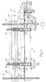
- the illustrated dumper comprises a tipping structure 2 with a rail car platform 4 formed a rail track 4′ secured on a bottom beam 6, comprising two elongate box sections 6a with integral webs 6b, which extends between respective end rings 8 of the structure that are mounted on rollers 10 for rotation of the structure about a common centre of the rings.
- Drive means (not shown) to rotate the structure may be of conventional form, eg. comprising an electric motor acting on gear rings fixed on one or both end rings.
- the bottom beam carries top clamping means 12 for a rail car on the platform.
- the tipping structure also includes side beams at opposite sides of the rail car platform.
- Each beam consists of a main length 16 extending between and secured to the horns 14 of the clamping means on that side of the platform, and end portions 18,20 that project from the horns through the end rings 8 to terminate in or near the same vertical plane as the corresponding end of the rail car platform 4.
- the bottom beam 6, horns 14 and side beams 16 are an essentially rigid, eg. welded, assembly.
- the end rings 8 are pin-jointed to the welded assembly by connecting pins 20 and the side beam extensions are pin-jointed to their end rings and the welded structure, by connecting pins 22,24 respectively.
- the pins 20,22,24 have their axes horizontal in the upright position of the dumper shown in Fig.
- the clamping mechanism mounted in each pair of horns 14 comprises a clamping bar 30 disposed between the horns of the pair and connected to the horns through a parallel motion linkage comprising a pair of links 32, so that a hook 34 at the top of the bar 30 can be moved into and out of engagement with the top of a rail car R on the platform.
- each hook With the tipping structure upright, each hook is held in a raised, inoperative position by a counter-weight 36 that is connected to the links 32 to pivot therewith.
- the mechanism appearing on the left-hand side of the platform in Fig. 2 has the counter-weight 36 on the end of an arm 38 secured to a torque bar 40 that is fixed to and forms the pivot connection of the lower link to its horn.
- the counter-weight 36 is on one end of a cranked lever 42 the pivot 44 of which is fixed relative to the horns 14, the other end of the lever being connected by a further link 46 to the lower of the parallel motion links 32; the difference between the mechanisms is due to the different clearance needs for the movement of the counter-weights on each side of the platform 4 to operate the clamping hooks 34 when the structure is rotated anti-clockwise, as indicated by the arrow A, to dump the contents of the rail car into a hopper H directly below the dumper.
- Fig. 2 also illustrates a fairing 52 provided over the side beam 16,18,20 on the left-hand side of the platform for guidance of the material being dumped into the hopper H as the rotary structure begins to be tipped.
- a rail car is driven onto the rail track 4′ on the platform 4 from the fixed track 50 while the platform is in its upright position shown in Figs. 1 and 2.
- the tipping structure is then rotated in the direction A and, as the platform begins to tilt, the side of the rail car comes to bear against the side beam 16,18,20 on the left-hand side of Fig. 2.
- the counter-weights 36 still hold the clamping hooks 34 raised because they lie to the left of their suspending pivots 40,44 as seen in Fig. 2.
- the tipping angle reaches some 10°, the centre of gravity of each counter-weight passes through a vertical plane from the respective pivot.
- locking devices which may be of conventional form, such as single-acting hydraulic cylinders, are connected to each clamping mechanism to be actuated by trip means once the hooks have engaged the rail car.
- Alternative locking devices are illustrated, however, in the form of "BEAR-LOC” friction units 54 (from Sacol Powerline Limited of Totton, Victoria, UK) connected to each clamping mechanism.
- These proprietary units comprise concentric inner and outer sleeves 56 through which a rod 58 extends. The sleeves are axially fixed relative to each other and the rod is normally locked frictionally by an interference fit with the inner sleeve.
- Hydraulic fluid can be supplied under pressure to the interface between the rod and the inner sleeve, so relaxing the interference fit and allowing the rod to slide in the sleeve. In its inoperative position, therefore, while the clamping hooks 34 are raised, hydraulic pressure is applied to the locking devices to allow the rods to move freely.
- the hooks are locked in their operative position by trips (not shown) between the clamping mechanisms and the tipping structure releasing the hydraulic pressure.
- the trips act conversely to reapply hydraulic pressure to the locking devices as the emptied rail car is returned to the upright position.
- the gravity operated clamping mechanism raises the hooks.
- the dumper is designed for discharging unit trains, in which rail cars remain coupled together with a limited fixed spacing between adjacent cars.
- Known installations of this kind have to be designed for a specific length of rail car.
- the illustrated installation is arranged to be capable of dealing with two different standard lengths of rail car, ie. a shorter length car R′ in addition to the car R shown on the tipping structure in Fig. 1.
- there is an intermediate linking section of track between the rail track on the rail car platform and the fixed track leading to the platform this section being formed alternatively by an extension 60 on the platform or by an extension 60a of the adjacent fixed track section, both sections carrying rails that can be aligned with the main track section of the platform and with the adjacent fixed track.
- the platform extension 60 is shown in operative position in Fig. 1 to deal with the longer length rail car R.
- the platform extension 60 is connected to the platform through a hinge 62 and is supported in its operative position by struts 64 pivoted on lugs 66 projecting from the bottom beam 6.
- a hydraulic ram 68 has pivot connections 70,72 to the bottom beam and the struts respectively.
- Each strut 64 carries a roller 74 that bears on a cam track 76 depending from the platform extension and in the state shown the ram 68 has been extended to bring the roller to the lower end of the cam track so that the struts support the extension 60 in its horizontal, linking position.
- the rollers 74 ride along the cam track 76 to its upper end as the extension 60 is allowed to swing down under its own weight to a substantially vertical position.
- the fixed track extension 60a and its displacement mechanism are identical and in mirror image to the platform extension 60; the parts are indicated by the same reference numbers but with the suffix "a".
- Fig. 1 the fixed track extension is of course shown in its substantially vertical collapsed condition and the manner of its adjustment will be clear from the preceding description of the tipping structure extension.
- the counterpart extension 60a on the fixed track can be raised to the linking position, forming a projecting end of the fixed track to the shorter length rotary tipping structure for the rail car R′.
Landscapes
- Engineering & Computer Science (AREA)
- Aviation & Aerospace Engineering (AREA)
- Mechanical Engineering (AREA)
- Refuge Islands, Traffic Blockers, Or Guard Fence (AREA)
- Body Structure For Vehicles (AREA)
- Vehicle Cleaning, Maintenance, Repair, Refitting, And Outriggers (AREA)
- Platform Screen Doors And Railroad Systems (AREA)
- Pivots And Pivotal Connections (AREA)
Applications Claiming Priority (2)
| Application Number | Priority Date | Filing Date | Title |
|---|---|---|---|
| GB888819012A GB8819012D0 (en) | 1988-08-10 | 1988-08-10 | Rail car dumpers |
| GB8819012 | 1988-08-10 |
Publications (3)
| Publication Number | Publication Date |
|---|---|
| EP0354751A2 EP0354751A2 (en) | 1990-02-14 |
| EP0354751A3 EP0354751A3 (en) | 1991-06-05 |
| EP0354751B1 true EP0354751B1 (en) | 1995-01-11 |
Family
ID=10641913
Family Applications (1)
| Application Number | Title | Priority Date | Filing Date |
|---|---|---|---|
| EP89308021A Expired - Lifetime EP0354751B1 (en) | 1988-08-10 | 1989-08-07 | Rail car dumpers |
Country Status (8)
| Country | Link |
|---|---|
| US (1) | US5017077A (ref) |
| EP (1) | EP0354751B1 (ref) |
| CN (1) | CN1019184B (ref) |
| CA (1) | CA1301547C (ref) |
| DE (1) | DE68920505T2 (ref) |
| GB (1) | GB8819012D0 (ref) |
| IN (1) | IN173318B (ref) |
| ZW (2) | ZW9489A1 (ref) |
Cited By (2)
| Publication number | Priority date | Publication date | Assignee | Title |
|---|---|---|---|---|
| DE202010007494U1 (de) | 2010-06-01 | 2010-08-26 | ThyssenKrupp Fördertechnik GmbH | Entladevorrichtung für offene Transportwagen |
| DE102010022384A1 (de) | 2010-06-01 | 2011-12-01 | ThyssenKrupp Fördertechnik GmbH | Entladevorrichtung für offene Transportwagen |
Families Citing this family (14)
| Publication number | Priority date | Publication date | Assignee | Title |
|---|---|---|---|---|
| US5509723A (en) * | 1993-10-15 | 1996-04-23 | Columbia Trailer Co., Inc. | Portable rotary trailer tipper |
| GB9507981D0 (en) * | 1995-04-19 | 1995-06-07 | Strachan & Henshaw Ltd | Dumper installations |
| US7322785B2 (en) | 2001-05-31 | 2008-01-29 | Air Cure, Inc. | Car dumper dust collection method and apparatus |
| US6960054B2 (en) | 2001-05-31 | 2005-11-01 | Air Cure, Inc. | Car dumper dust collection method and apparatus |
| US7083375B2 (en) * | 2001-12-27 | 2006-08-01 | Cargill, Incorporated | System and method for transporting and handling bulk quantities of bulk feed |
| BRPI0721030B1 (pt) * | 2007-02-08 | 2018-08-14 | Dalian Huarui Heavy Industry Group Co., Ltd. | Dispositivo da reviravolta do amortecimento do carro |
| DE102008047716B8 (de) * | 2008-09-18 | 2010-08-05 | ThyssenKrupp Fördertechnik GmbH | Verfahren und Drehkipper zum Entleeren von oben offenen Eisenbahnwaggons |
| US7959398B2 (en) | 2008-12-11 | 2011-06-14 | Air-Cure Incorporated | Car dumper dust control system |
| US9090415B2 (en) | 2012-09-05 | 2015-07-28 | General Electric Company | System and method for rolling a vehicle to unload cargo |
| CN104973003B (zh) * | 2014-11-06 | 2017-11-28 | 陈从龙 | 汽车行驶不翻车的安全装置 |
| DE102015000667A1 (de) * | 2015-01-23 | 2016-07-28 | Thyssenkrupp Ag | Kippvorrichtung sowie Verfahren zum Betreiben einer Kippvorrichtung |
| CN105540293B (zh) * | 2016-01-26 | 2017-11-10 | 周艳 | 用于矿山轨道车辆的卸载装置 |
| US10364107B2 (en) | 2016-05-27 | 2019-07-30 | Richmond Engineering Works L.L.C. | Trunnion assembly for rotary dumper |
| CN113911763B (zh) * | 2020-09-04 | 2023-03-28 | 安徽省凯杰机械制造有限公司 | 散粮后卸平台专用接粮仓 |
Family Cites Families (11)
| Publication number | Priority date | Publication date | Assignee | Title |
|---|---|---|---|---|
| US1821217A (en) * | 1928-05-07 | 1931-09-01 | Link Belt Co | Hydraulic clamp for rotary car dumpers |
| US2533090A (en) * | 1948-05-17 | 1950-12-05 | Bur Armand | Car dumper sampling apparatus |
| GB802172A (en) * | 1956-01-14 | 1958-10-01 | Strachan & Henshaw Ltd | Improvements in or relating to rotary tipplers |
| US2896935A (en) * | 1956-03-08 | 1959-07-28 | Heyl & Patterson | Car dumper |
| DE1115640B (de) * | 1959-11-04 | 1961-10-19 | Krupp Ardelt Gmbh | Rundkipper fuer Wagen oder Behaelter, insbesondere Eisenbahn-Waggons |
| US3116843A (en) * | 1961-03-22 | 1964-01-07 | Anaconda Co | Rotary car dumper |
| US3220576A (en) * | 1963-04-24 | 1965-11-30 | Mcdowell Wellman Eng Co | Rotary railroad car dumping apparatus |
| US3373829A (en) * | 1966-07-20 | 1968-03-19 | Link Bell Company | Weighing mechanism for railroad car dumpers |
| GB1271687A (en) * | 1969-04-22 | 1972-04-26 | Strachan & Henshaw Ltd | Improvements in or relating to tipplers |
| US4024962A (en) * | 1975-10-06 | 1977-05-24 | The Mcdowell-Wellman Engineering Company | Car dumper scale |
| US4043467A (en) * | 1976-10-07 | 1977-08-23 | Fmc Corporation | Rotary car dumper with shiftable frame |
-
1988
- 1988-08-10 GB GB888819012A patent/GB8819012D0/en active Pending
-
1989
- 1989-08-02 CN CN89106312.9A patent/CN1019184B/zh not_active Expired
- 1989-08-03 US US07/389,171 patent/US5017077A/en not_active Expired - Fee Related
- 1989-08-07 EP EP89308021A patent/EP0354751B1/en not_active Expired - Lifetime
- 1989-08-07 DE DE68920505T patent/DE68920505T2/de not_active Expired - Fee Related
- 1989-08-08 IN IN587MA1989 patent/IN173318B/en unknown
- 1989-08-09 ZW ZW94/89A patent/ZW9489A1/xx unknown
- 1989-08-09 ZW ZW95/89A patent/ZW9589A1/xx unknown
- 1989-08-09 CA CA000607850A patent/CA1301547C/en not_active Expired - Lifetime
Cited By (3)
| Publication number | Priority date | Publication date | Assignee | Title |
|---|---|---|---|---|
| DE202010007494U1 (de) | 2010-06-01 | 2010-08-26 | ThyssenKrupp Fördertechnik GmbH | Entladevorrichtung für offene Transportwagen |
| DE102010022384A1 (de) | 2010-06-01 | 2011-12-01 | ThyssenKrupp Fördertechnik GmbH | Entladevorrichtung für offene Transportwagen |
| DE102010022384B4 (de) * | 2010-06-01 | 2020-10-08 | Thyssenkrupp Industrial Solutions Ag | Entladevorrichtung für offene Transportwagen |
Also Published As
| Publication number | Publication date |
|---|---|
| DE68920505D1 (de) | 1995-02-23 |
| CN1045747A (zh) | 1990-10-03 |
| ZW9589A1 (en) | 1990-02-14 |
| ZW9489A1 (en) | 1990-02-14 |
| EP0354751A2 (en) | 1990-02-14 |
| CA1301547C (en) | 1992-05-26 |
| DE68920505T2 (de) | 1995-07-13 |
| GB8819012D0 (en) | 1988-09-14 |
| CN1019184B (zh) | 1992-11-25 |
| US5017077A (en) | 1991-05-21 |
| EP0354751A3 (en) | 1991-06-05 |
| IN173318B (ref) | 1994-04-02 |
Similar Documents
| Publication | Publication Date | Title |
|---|---|---|
| EP0354751B1 (en) | Rail car dumpers | |
| US5203442A (en) | Cantilever conveying techniques | |
| WO2017212115A1 (en) | Load handling device for a transportation unit, and a transportation unit with said device | |
| US4922832A (en) | Intermodal road/rail transportation system | |
| US6425333B2 (en) | Loading car for bulk materials | |
| CN114655264A (zh) | 单侧倾卸的铁路自翻车 | |
| US3532061A (en) | Separable wheeled freight vehicle | |
| RU2106985C1 (ru) | Транспортное средство с опрокидывающимся кузовом | |
| US4592693A (en) | Carrying platform for receiving a goods van or container and provided with means for its adaptation to transport by road, rail and sea | |
| US6494330B1 (en) | Variable length crane jib with automatic balancing | |
| US3865347A (en) | Apparatus for unloading bulk material | |
| GB2212132A (en) | Apparatus for a folding-down loader tailboard | |
| US8062579B2 (en) | Device for moving a runner | |
| CA2254702A1 (en) | Portable overhead bin | |
| SU1586936A2 (ru) | Приспособление к автосамосвалу дл загрузки сельскохоз йственных машин | |
| US3268099A (en) | Universal power conveyor | |
| EP3684721A1 (en) | Trolley of a crane | |
| CN100379605C (zh) | 升降装卸平台系统 | |
| US20230339522A1 (en) | Large plate tilt railroad car | |
| NL1011906C2 (nl) | Hijskraan. | |
| US12509129B2 (en) | Large plate tilt railroad car | |
| US4981410A (en) | Swinging-linkages rotary loader | |
| KR100218192B1 (ko) | 화물 운반장치 | |
| SU998251A1 (ru) | Ленточный конвейер | |
| US3305111A (en) | Elevator gate |
Legal Events
| Date | Code | Title | Description |
|---|---|---|---|
| PUAI | Public reference made under article 153(3) epc to a published international application that has entered the european phase |
Free format text: ORIGINAL CODE: 0009012 |
|
| AK | Designated contracting states |
Kind code of ref document: A2 Designated state(s): BE DE FR GB IT NL SE |
|
| PUAL | Search report despatched |
Free format text: ORIGINAL CODE: 0009013 |
|
| AK | Designated contracting states |
Kind code of ref document: A3 Designated state(s): BE DE FR GB IT NL SE |
|
| 17P | Request for examination filed |
Effective date: 19910909 |
|
| 17Q | First examination report despatched |
Effective date: 19920707 |
|
| GRAA | (expected) grant |
Free format text: ORIGINAL CODE: 0009210 |
|
| AK | Designated contracting states |
Kind code of ref document: B1 Designated state(s): BE DE FR GB IT NL SE |
|
| REF | Corresponds to: |
Ref document number: 68920505 Country of ref document: DE Date of ref document: 19950223 |
|
| ITF | It: translation for a ep patent filed | ||
| ET | Fr: translation filed | ||
| PLBE | No opposition filed within time limit |
Free format text: ORIGINAL CODE: 0009261 |
|
| STAA | Information on the status of an ep patent application or granted ep patent |
Free format text: STATUS: NO OPPOSITION FILED WITHIN TIME LIMIT |
|
| 26N | No opposition filed | ||
| REG | Reference to a national code |
Ref country code: GB Ref legal event code: 732E |
|
| REG | Reference to a national code |
Ref country code: GB Ref legal event code: IF02 |
|
| PGFP | Annual fee paid to national office [announced via postgrant information from national office to epo] |
Ref country code: GB Payment date: 20020805 Year of fee payment: 14 |
|
| PGFP | Annual fee paid to national office [announced via postgrant information from national office to epo] |
Ref country code: FR Payment date: 20020821 Year of fee payment: 14 |
|
| PGFP | Annual fee paid to national office [announced via postgrant information from national office to epo] |
Ref country code: DE Payment date: 20020824 Year of fee payment: 14 |
|
| PGFP | Annual fee paid to national office [announced via postgrant information from national office to epo] |
Ref country code: SE Payment date: 20020826 Year of fee payment: 14 |
|
| PGFP | Annual fee paid to national office [announced via postgrant information from national office to epo] |
Ref country code: NL Payment date: 20020827 Year of fee payment: 14 |
|
| PGFP | Annual fee paid to national office [announced via postgrant information from national office to epo] |
Ref country code: BE Payment date: 20020829 Year of fee payment: 14 |
|
| PG25 | Lapsed in a contracting state [announced via postgrant information from national office to epo] |
Ref country code: GB Free format text: LAPSE BECAUSE OF NON-PAYMENT OF DUE FEES Effective date: 20030807 |
|
| PG25 | Lapsed in a contracting state [announced via postgrant information from national office to epo] |
Ref country code: SE Free format text: LAPSE BECAUSE OF NON-PAYMENT OF DUE FEES Effective date: 20030808 |
|
| PG25 | Lapsed in a contracting state [announced via postgrant information from national office to epo] |
Ref country code: BE Free format text: LAPSE BECAUSE OF NON-PAYMENT OF DUE FEES Effective date: 20030831 |
|
| BERE | Be: lapsed |
Owner name: *STRACHAN & HENSHAW LTD Effective date: 20030831 |
|
| PG25 | Lapsed in a contracting state [announced via postgrant information from national office to epo] |
Ref country code: NL Free format text: LAPSE BECAUSE OF NON-PAYMENT OF DUE FEES Effective date: 20040301 |
|
| PG25 | Lapsed in a contracting state [announced via postgrant information from national office to epo] |
Ref country code: DE Free format text: LAPSE BECAUSE OF NON-PAYMENT OF DUE FEES Effective date: 20040302 |
|
| EUG | Se: european patent has lapsed | ||
| GBPC | Gb: european patent ceased through non-payment of renewal fee |
Effective date: 20030807 |
|
| PG25 | Lapsed in a contracting state [announced via postgrant information from national office to epo] |
Ref country code: FR Free format text: LAPSE BECAUSE OF NON-PAYMENT OF DUE FEES Effective date: 20040430 |
|
| NLV4 | Nl: lapsed or anulled due to non-payment of the annual fee |
Effective date: 20040301 |
|
| REG | Reference to a national code |
Ref country code: FR Ref legal event code: ST |
|
| PG25 | Lapsed in a contracting state [announced via postgrant information from national office to epo] |
Ref country code: IT Free format text: LAPSE BECAUSE OF NON-PAYMENT OF DUE FEES;WARNING: LAPSES OF ITALIAN PATENTS WITH EFFECTIVE DATE BEFORE 2007 MAY HAVE OCCURRED AT ANY TIME BEFORE 2007. THE CORRECT EFFECTIVE DATE MAY BE DIFFERENT FROM THE ONE RECORDED. Effective date: 20050807 |