EP0353763B2 - Kraftstoffversorgungsvorrichtung eines Motors - Google Patents
Kraftstoffversorgungsvorrichtung eines Motors Download PDFInfo
- Publication number
- EP0353763B2 EP0353763B2 EP89114397A EP89114397A EP0353763B2 EP 0353763 B2 EP0353763 B2 EP 0353763B2 EP 89114397 A EP89114397 A EP 89114397A EP 89114397 A EP89114397 A EP 89114397A EP 0353763 B2 EP0353763 B2 EP 0353763B2
- Authority
- EP
- European Patent Office
- Prior art keywords
- needle
- insertion bore
- needle insertion
- pressurized air
- nozzle
- Prior art date
- Legal status (The legal status is an assumption and is not a legal conclusion. Google has not performed a legal analysis and makes no representation as to the accuracy of the status listed.)
- Expired - Lifetime
Links
- 239000000446 fuel Substances 0.000 title claims description 82
- 230000037431 insertion Effects 0.000 claims description 50
- 238000003780 insertion Methods 0.000 claims description 50
- 238000002347 injection Methods 0.000 claims description 5
- 239000007924 injection Substances 0.000 claims description 5
- 238000002485 combustion reaction Methods 0.000 description 9
- 230000006835 compression Effects 0.000 description 4
- 238000007906 compression Methods 0.000 description 4
- 239000007788 liquid Substances 0.000 description 3
- OKTJSMMVPCPJKN-UHFFFAOYSA-N Carbon Chemical compound [C] OKTJSMMVPCPJKN-UHFFFAOYSA-N 0.000 description 2
- 229910052799 carbon Inorganic materials 0.000 description 2
- 230000000873 masking effect Effects 0.000 description 2
- 230000001788 irregular Effects 0.000 description 1
- 239000000203 mixture Substances 0.000 description 1
- 230000002093 peripheral effect Effects 0.000 description 1
- 230000002000 scavenging effect Effects 0.000 description 1
Images

Classifications
-
- F—MECHANICAL ENGINEERING; LIGHTING; HEATING; WEAPONS; BLASTING
- F02—COMBUSTION ENGINES; HOT-GAS OR COMBUSTION-PRODUCT ENGINE PLANTS
- F02M—SUPPLYING COMBUSTION ENGINES IN GENERAL WITH COMBUSTIBLE MIXTURES OR CONSTITUENTS THEREOF
- F02M51/00—Fuel-injection apparatus characterised by being operated electrically
- F02M51/06—Injectors peculiar thereto with means directly operating the valve needle
- F02M51/061—Injectors peculiar thereto with means directly operating the valve needle using electromagnetic operating means
- F02M51/0625—Injectors peculiar thereto with means directly operating the valve needle using electromagnetic operating means characterised by arrangement of mobile armatures
- F02M51/0664—Injectors peculiar thereto with means directly operating the valve needle using electromagnetic operating means characterised by arrangement of mobile armatures having a cylindrically or partly cylindrically shaped armature, e.g. entering the winding; having a plate-shaped or undulated armature entering the winding
- F02M51/0671—Injectors peculiar thereto with means directly operating the valve needle using electromagnetic operating means characterised by arrangement of mobile armatures having a cylindrically or partly cylindrically shaped armature, e.g. entering the winding; having a plate-shaped or undulated armature entering the winding the armature having an elongated valve body attached thereto
-
- F—MECHANICAL ENGINEERING; LIGHTING; HEATING; WEAPONS; BLASTING
- F02—COMBUSTION ENGINES; HOT-GAS OR COMBUSTION-PRODUCT ENGINE PLANTS
- F02M—SUPPLYING COMBUSTION ENGINES IN GENERAL WITH COMBUSTIBLE MIXTURES OR CONSTITUENTS THEREOF
- F02M51/00—Fuel-injection apparatus characterised by being operated electrically
- F02M51/02—Fuel-injection apparatus characterised by being operated electrically specially for low-pressure fuel-injection
-
- F—MECHANICAL ENGINEERING; LIGHTING; HEATING; WEAPONS; BLASTING
- F02—COMBUSTION ENGINES; HOT-GAS OR COMBUSTION-PRODUCT ENGINE PLANTS
- F02M—SUPPLYING COMBUSTION ENGINES IN GENERAL WITH COMBUSTIBLE MIXTURES OR CONSTITUENTS THEREOF
- F02M51/00—Fuel-injection apparatus characterised by being operated electrically
- F02M51/06—Injectors peculiar thereto with means directly operating the valve needle
- F02M51/061—Injectors peculiar thereto with means directly operating the valve needle using electromagnetic operating means
- F02M51/0625—Injectors peculiar thereto with means directly operating the valve needle using electromagnetic operating means characterised by arrangement of mobile armatures
- F02M51/0664—Injectors peculiar thereto with means directly operating the valve needle using electromagnetic operating means characterised by arrangement of mobile armatures having a cylindrically or partly cylindrically shaped armature, e.g. entering the winding; having a plate-shaped or undulated armature entering the winding
- F02M51/0671—Injectors peculiar thereto with means directly operating the valve needle using electromagnetic operating means characterised by arrangement of mobile armatures having a cylindrically or partly cylindrically shaped armature, e.g. entering the winding; having a plate-shaped or undulated armature entering the winding the armature having an elongated valve body attached thereto
- F02M51/0675—Injectors peculiar thereto with means directly operating the valve needle using electromagnetic operating means characterised by arrangement of mobile armatures having a cylindrically or partly cylindrically shaped armature, e.g. entering the winding; having a plate-shaped or undulated armature entering the winding the armature having an elongated valve body attached thereto the valve body having cylindrical guiding or metering portions, e.g. with fuel passages
-
- F—MECHANICAL ENGINEERING; LIGHTING; HEATING; WEAPONS; BLASTING
- F02—COMBUSTION ENGINES; HOT-GAS OR COMBUSTION-PRODUCT ENGINE PLANTS
- F02M—SUPPLYING COMBUSTION ENGINES IN GENERAL WITH COMBUSTIBLE MIXTURES OR CONSTITUENTS THEREOF
- F02M51/00—Fuel-injection apparatus characterised by being operated electrically
- F02M51/06—Injectors peculiar thereto with means directly operating the valve needle
- F02M51/08—Injectors peculiar thereto with means directly operating the valve needle specially for low-pressure fuel-injection
-
- F—MECHANICAL ENGINEERING; LIGHTING; HEATING; WEAPONS; BLASTING
- F02—COMBUSTION ENGINES; HOT-GAS OR COMBUSTION-PRODUCT ENGINE PLANTS
- F02M—SUPPLYING COMBUSTION ENGINES IN GENERAL WITH COMBUSTIBLE MIXTURES OR CONSTITUENTS THEREOF
- F02M53/00—Fuel-injection apparatus characterised by having heating, cooling or thermally-insulating means
- F02M53/04—Injectors with heating, cooling, or thermally-insulating means
- F02M53/08—Injectors with heating, cooling, or thermally-insulating means with air cooling
-
- F—MECHANICAL ENGINEERING; LIGHTING; HEATING; WEAPONS; BLASTING
- F02—COMBUSTION ENGINES; HOT-GAS OR COMBUSTION-PRODUCT ENGINE PLANTS
- F02M—SUPPLYING COMBUSTION ENGINES IN GENERAL WITH COMBUSTIBLE MIXTURES OR CONSTITUENTS THEREOF
- F02M61/00—Fuel-injectors not provided for in groups F02M39/00 - F02M57/00 or F02M67/00
- F02M61/04—Fuel-injectors not provided for in groups F02M39/00 - F02M57/00 or F02M67/00 having valves, e.g. having a plurality of valves in series
- F02M61/08—Fuel-injectors not provided for in groups F02M39/00 - F02M57/00 or F02M67/00 having valves, e.g. having a plurality of valves in series the valves opening in direction of fuel flow
-
- F—MECHANICAL ENGINEERING; LIGHTING; HEATING; WEAPONS; BLASTING
- F02—COMBUSTION ENGINES; HOT-GAS OR COMBUSTION-PRODUCT ENGINE PLANTS
- F02M—SUPPLYING COMBUSTION ENGINES IN GENERAL WITH COMBUSTIBLE MIXTURES OR CONSTITUENTS THEREOF
- F02M67/00—Apparatus in which fuel-injection is effected by means of high-pressure gas, the gas carrying the fuel into working cylinders of the engine, e.g. air-injection type
- F02M67/02—Apparatus in which fuel-injection is effected by means of high-pressure gas, the gas carrying the fuel into working cylinders of the engine, e.g. air-injection type the gas being compressed air, e.g. compressed in pumps
-
- F—MECHANICAL ENGINEERING; LIGHTING; HEATING; WEAPONS; BLASTING
- F02—COMBUSTION ENGINES; HOT-GAS OR COMBUSTION-PRODUCT ENGINE PLANTS
- F02M—SUPPLYING COMBUSTION ENGINES IN GENERAL WITH COMBUSTIBLE MIXTURES OR CONSTITUENTS THEREOF
- F02M67/00—Apparatus in which fuel-injection is effected by means of high-pressure gas, the gas carrying the fuel into working cylinders of the engine, e.g. air-injection type
- F02M67/10—Injectors peculiar thereto, e.g. valve less type
- F02M67/12—Injectors peculiar thereto, e.g. valve less type having valves
-
- F—MECHANICAL ENGINEERING; LIGHTING; HEATING; WEAPONS; BLASTING
- F02—COMBUSTION ENGINES; HOT-GAS OR COMBUSTION-PRODUCT ENGINE PLANTS
- F02M—SUPPLYING COMBUSTION ENGINES IN GENERAL WITH COMBUSTIBLE MIXTURES OR CONSTITUENTS THEREOF
- F02M69/00—Low-pressure fuel-injection apparatus ; Apparatus with both continuous and intermittent injection; Apparatus injecting different types of fuel
- F02M69/08—Low-pressure fuel-injection apparatus ; Apparatus with both continuous and intermittent injection; Apparatus injecting different types of fuel characterised by the fuel being carried by compressed air into main stream of combustion-air
-
- F—MECHANICAL ENGINEERING; LIGHTING; HEATING; WEAPONS; BLASTING
- F02—COMBUSTION ENGINES; HOT-GAS OR COMBUSTION-PRODUCT ENGINE PLANTS
- F02B—INTERNAL-COMBUSTION PISTON ENGINES; COMBUSTION ENGINES IN GENERAL
- F02B75/00—Other engines
- F02B75/02—Engines characterised by their cycles, e.g. six-stroke
- F02B2075/022—Engines characterised by their cycles, e.g. six-stroke having less than six strokes per cycle
- F02B2075/025—Engines characterised by their cycles, e.g. six-stroke having less than six strokes per cycle two
Definitions
- the present invention relates to a fuel supply device of an engine according to the preamble of claim 1.
- JP-A-61 104 154 there is disclosed a generic fuel supply device, wherein the opening and closing operation of a nozzle opening is controlled by a needle to inject a fuel by pressurized air.
- a pressurized air passage extending from the nozzle opening along the needle is formed around the needle, thereby forming a needle insertion bore.
- a pressurized air outflow passage extends from a pressurized fuel source to one end of the needle insertion bore located opposite to the nozzle opening.
- the pressurized air introduced from the pressurized air outflow passage into the needle insertion bore substantially flows in such a manner that fuel accumulates on the inner wall of the deep portion of the needle insertion near the connecting portion with the pressurized air outflow passage.
- An object of the present invention is to provide a fuel supply device capable of injecting the entire fuel, injected by means of the fuel injector, from the nozzle opening of the fuel supply device.
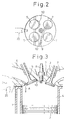
- Masking walls 10, each masking the valve opening formed between the valve seat and the peripheral portion of the intake valve 5, which is located on the exhaust valve side, for the entire time for which the intake valve 5 is open, are formed on the inner wall of the cylinder head 3. Consequently, when the intake valves 5 open, fresh air flows into the combustion chamber 4 from the valve opening which is located at a position opposite to the exhaust valves 7, as illustrated by the arrow A in Fig. 3.
- a fuel supply device 20 is arranged on the inner wall of the cylinder head 3 between the intake valves 5.
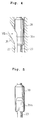
- the fuel supply device 20 in Fig. 1 does not show the invention, but only illustrates features which are present in an embodiment of the invention shown in Figs. 4 and 5.
- a straight needle insertion bore 22 is formed in the housing 21 of the fuel supply device 20, and a needle 23 having a diameter smaller than that of the needle insertion bore 22 is inserted into the needle insertion bore 22.
- a nozzle opening 24 is formed at one end of the needle insertion bore 22, and the opening and closing operation of the nozzle opening 24 is carried out by the valve head 25 formed on the tip of the needle 23.
- the nozzle opening 24 is arranged in the combustion chamber 4.
- a spring retainer 26 is mounted on the needle 23, and a compression spring 27 is inserted between the spring retainer 26 and the housing 21. The nozzle opening 24 is normally closed by the valve head 25 of the needle 23 due to the spring force of the compression spring 27.
- a movable core 28 continuously abuts against the end portion of the needle 23, which is positioned opposite to the valve head 25, due to the spring force of the compression spring 27, and a solenoid 30 and a stator 31 are arranged in the housing 21 to attract the movable core 28.
- the solenoid 30 is energized, the movable core 28 moves toward the stator 31.
- the needle 23 moves toward the nozzle opening 24 against the compression spring 27, the nozzle opening 24 is opened.
- a nozzle chamber 32 having a cylindrical shape is formed in the housing 21.
- the nozzle chamber 32 has an air inlet 32a and an air outlet 32b separately formed from and spaced from the air inlet 32a.
- the air inlet 32a is connected to a pressurized air source 34 via a pressurized air inflow passage 33, and the air outlet 32b is connected to the needle insertion bore 22 via a pressurized air outflow passage 35.
- the nozzle 37 of a fuel injector 36 is arranged in the nozzle chamber 32 at a position between the air inlet 32a and the air outlet 32b.
- the pressurized air outlet passage 35 extends straight.
- the nozzle 37 of the fuel injector 36 is arranged on the axis of the pressurized air outlet passage 35, and fuel having a small spread angle is injected from the nozzle 37 along the axis of the pressurized air outflow passage 35.
- the pressurized air outlet passage 35 extends obliquely to the needle insertion bore 22 toward the nozzle opening 24 and is obliquely connected to the needle insertion bore 22 at an angle of 20 through 40 degrees with respect to the axis of the needle insertion bore 22.
- the needle insertion bore 22, the nozzle chamber 32, and the pressurized air outflow passage 35 are connected to the pressurized air source 34 via the pressurized air inflow passage 33 and thus filled with pressurized air.
- Fuel is injected into the pressurized air from the nozzle 37 along the axis of the pressurized air outflow passage 35. Since the pressurized air outflow passage 35 is obliquely connected to the needle insertion bore 22, a large part of the injected fuel reaches the interior of the needle insertion bore 22 around the needle 23 near the valve head 25. At this time, a part of the injected fuel is stuck to both the inner wall of the pressurized air outflow passage 35 and the inner wall of the nozzle chamber 32.
- the needle 23 opens the nozzle opening 24.
- both the fuel and the pressurized air are injected together from the nozzle opening 24 into the combustion chamber 4 (Fig. 3) as soon as the needle 23 opens the nozzle opening 24.
- pressurized air flows into the nozzle chamber 32 from the pressurized air inflow passage 33 and then flows toward the nozzle opening 24 via the pressurized air outflow passage 35. Consequently, the fuel stuck to the inner wall of the pressurized air outflow passage 35 and the inner wall of the nozzle chamber 32 is carried away by the pressurized air and then injected from the nozzle opening 24.
- the needle 23 opens the nozzle opening 24
- the entire injected fuel is injected from the nozzle opening 24 and, after the injection of the entire injected fuel is completed, only the pressurized air is injected from the nozzle opening 24.
- the solenoid 30 is deenergized, and thus the needle 23 closes the nozzle opening 24. Consequently, only the pressurized air is injected from the nozzle opening 24 immediately before the needle 23 closes the nozzle opening 24.
- an enlarged portion 38 closing the entire cross-section of the needle insertion bore 22 is integrally formed on the needle 23 at a position adjacent to the connecting portion between the pressurized air outflow passage 35 and the needle insertion bore 22 and opposite to the nozzle opening 24.
- the enlarged portion 38 By forming the enlarged portion 38 on the needle 23, when fuel is injected from the nozzle 37 of the fuel injector 36, the enlarged portion 38 prevents the injected fuel from entering into the deep interior of the needle insertion bore 22, that is, entering into the needle insertion bore 22 located above the enlarged portion 38, and prevents the injected fuel from being stuck to the inner wall of the deep interior of the needle insertion bore 22. Consequently, the entire fuel injected from the nozzle 37 can be injected from the nozzle opening 24. In addition, when the needle 23 opens the nozzle opening 24, the enlarged portion 38 moves toward the nozzle opening 24. At this time, the fuel stuck onto the inner wall of the needle insertion bore 22 near the enlarged portion 38 is wiped off by the lower end face of the enlarged portion 38. Consequently, it is possible to prevent the fuel from accumulating on the inner wall of the needle insertion bore 22 near the enlarged portion 38.
- the enlarged portion 38 also serves to retain the needle 23 at a regular position in the needle insertion bore 22.
- Figure 3 illustrates the case where the fuel supply device 20 is used for a two-stroke engine, and the injection of fuel by the fuel supply device 20 is started a little while before the intake valves 5 close.
- FIGs 4 and 5 illustrate an embodiment of the fuel supply device according to the invention.
- the enlarged portion 39 of the needle 23 is arranged to cover the opening of the pressurized air outflow passage 35, and a cutaway portion 39a is formed on the outer circumferential wall of the enlarged portion 41 at a position which faces the opening of the pressurized air outflow passage 35.
- the fuel injected from the nozzle 37 (Fig. 1) impinges upon the surface of the cutaway portion 41a, which has a small surface area, the amount of fuel stuck to the wall around the opening of the pressurized air outflow passage 35 becomes small. Consequently, in this embodiment, there is an advantage that the amount of the injected fuel which reaches the needle insertion bore 22 near the valve head 25 can be increased.
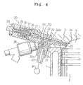
- FIG. 6 illustrates a further embodiment of the fuel supply device.
- another air outlet 32c is formed on the inner circumferential wall of the nozzle chamber 32 at a position opposite to the air inlet 32a with respect to the axis of the pressurized air outflow passage 35.
- This air outlet 32c is obliquely connected to the nozzle insertion bore 22 via a bypass passage 70 so that the distance between the nozzle opening 24 and the connecting portion of the pressurized air outlet passage 35 and the needle insertion bore 22 is approximately one half of the distance between the nozzle opening 24 and the connecting portion of the bypass passage 70 and the needle insertion bore 22.
- the entire fuel injected from the fuel injector is injected from the nozzle opening together with the pressurized air, there is no danger that the amount of fuel injected from the nozzle opening becomes irregular, and thus it is possible to obtain stable combustion.
Landscapes
- Engineering & Computer Science (AREA)
- Chemical & Material Sciences (AREA)
- Combustion & Propulsion (AREA)
- Mechanical Engineering (AREA)
- General Engineering & Computer Science (AREA)
- Physics & Mathematics (AREA)
- Electromagnetism (AREA)
- Fuel-Injection Apparatus (AREA)
Claims (7)
- Kraftstoffversorgungsvorrichtung eines Motors, miteiner Düsenöffnung (24) zum Einspritzen von Kraftstoff und unter Druck gesetzter Luft,einer Ventileinrichtung (20) mit einer Nadel (23), die in einer Nadeleinführbohrung (22) mit einem Durchmesser größer als der der Nadel angeordnet ist, zum elektromagnetischen Steuern des Öffnungsvorgangs der Düsenöffnung (24), die an einem Spitzenende der Nadeleinführbohrung ausgebildet ist;einer Düsenkammer (32) mit einem mit einer Druckluftquelle (34) verbundenen Lufteinlaß (32a) und einem getrennt vom ausgebildeten und im Abstand vom Lufteinlaß angeordneten und mit der Nadeleinführbohrung über einen Druckluftausströmdurchlaß (35) verbundenen Luftauslaß (32b);einer in der Düsenkammer angeordneten Kraftstoffeinspritzeinrichtung (36) zum Einspritzen von Kraftstoff, dadurch gekennzeichnet, daß die Nadel (23) einen daran ausgebildeten vergrößerten Abschnitt (39) hat, wobei der vergrößerte Abschnitt den gesamten Querschnitt der Nadeleinführbohrung schließt und gleitfähig in die Nadeleinführbohrung (22) eingepaßt ist bei einer zu der Düsenöffnung (24) entgegengesetzten Stelle bezüglich einem Verbindungsabschnitt des Druckluftausströmdurchlasses (35) und der Nadeleinführbohrung, wobei der Druckluftausströmdurchlaß (35) schräg mit der Nadeleinführbohrung (22) verbunden ist und der vergrößerte Abschnitt (39) einen Einschnittabschnitt (39a) hat, der den Druckluftausströmdurchlaß (35) mit der Düsenöffnung (24) verbindet.
- Kraftstoffversorgungsvorrichtung nach Anspruch 1, dadurch gekennzeichnet, daß die Ventileinrichtung (20) weiterhin einen Elektromagneten (30) aufweist, der die Nadel (23) betätigt und einen an der Nadel (23) ausgebildeten Ventilkopf (25), um den Öffnungsvorgang der Düsenöffnung (24) zu steuern.
- Kraftstoffversorgungsvorrichtung nach Anspruch 1, dadurch gekennzeichnet, daß die Düsenkammer (32) eine sich um eine Achse der Düsenkammer (32) umfangsseitig erstreckende innere Umfangswand aufweist und daß der Lufteinlaß (32a) an der Umfangswand der Düsenkammer (32) ausgebildet ist, wobei der Luftauslaß (32b) an der Achse der Düsenkammer (32) ausgebildet ist.
- Kraftstoffversorgungsvorrichtung nach Anspruch 3, dadurch gekennzeichnet, daß die Kraftstoffeinspritzeinrichtung (36) eine an der Achse der Düsenkammer (32) angeordnete Düse (37) aufweist, um Kraftstoff aus der Düse (37) entlang der Achse der Düsenkammer (32) einzuspritzen.
- Kraftstoffversorgungsvorrichtung nach Anspruch 4, dadurch gekennzeichnet, daß der Luftauslaß (32b) über einen Druckluftausströmdurchlaß (35), der sich geradlinig an der Achse der Düsenkammer (32) erstreckt, mit der Düsenöffnung (24) verbunden ist.
- Kraftstoffversorgungsvorrichtung eines Motors mitdie Nadel (23) einen daran ausgebildeten vergrößerten Abschnitt (39) hat, wobei der vergrößerte Abschnitt den gesamten Querschnitt der Nadeleinführbohrung schließt und gleitfähig in die Nadeleinführbohrung (22) eingepaßt ist bei einer zu der Düsenöffnung (24) entgegengesetzten Stelle bezüglich dem Verbindungsabschnitt des Bypassdurchlasses (70) und der Nadeleinführbohrung, undeiner Düsenöffnung (24) zum Einspritzen von Kraftstoff und unter Druck gesetzter Luft,einer Ventileinrichtung (20) mit einer Nadel (23), die in einer Nadeleinführbohrung (22) mit einem Durchmesser größer als der der Nadel angeordnet ist, zum elektromagnetischen Steuern des Öffnungsvorgangs der Düsenöffnung (24), die an einem Spitzenende der Nadeleinführbohrung ausgebildet ist;einer Düsenkammer (32) mit einem mit einer Druckluftquelle (34) verbundenen Lufteinlaß (32a) und einem getrennt vom ausgebildeten und im Abstand vom Lufteinlaß angeordneten und mit der Nadeleinführbohrung über einen Druckluftausströmdurchlaß (35) verbundenen Luftauslaß (32b); undeiner in der Düsenkammer angeordneten Kraftstoffeinspritzeinrichtung (36) zum Einspritzen von Kraftstoff, dadurch gekennzeichnet, daß die Düsenkammer (32) einen anderen Luftauslaß (32c) hat, der an der inneren Umfangswand der Düsenkammer ausgebildet ist und über einen Bypassdurchlaß (70) bei einer Stelle mit der Nadeleinführbohrung (22) verbunden ist, die entgegengesetzt zu der Düsenöffnung (24) ist bezüglich einem Verbindungsabschnitt des Druckluftausströmdurchlasses (35) und der Nadeleinführbohrung (22), wobei
wobei der Druckluftausströmdurchlaß (35) schräg mit der Nadeleinführbohrung (22) verbunden ist. - Kraftstoffversorgungsvorrichtung nach Anspruch 6, dadurch gekennzeichnet, daß der andere Luftauslaß (32c) bei einer Stelle entgegengesetzt zu dem Lufteinlaß (32a) bezüglich der Achse der Düsenkammer (32) angeordnet ist.
Applications Claiming Priority (12)
| Application Number | Priority Date | Filing Date | Title |
|---|---|---|---|
| JP102691/88U | 1988-08-04 | ||
| JP10269188U JPH0636289Y2 (ja) | 1988-08-04 | 1988-08-04 | 内燃機関の燃料噴射装置 |
| JP10269188U | 1988-08-04 | ||
| JP10406188U | 1988-08-08 | ||
| JP10406188 | 1988-08-08 | ||
| JP104061/88U | 1988-08-08 | ||
| JP115904/88U | 1988-09-05 | ||
| JP1988115904U JP2518278Y2 (ja) | 1988-09-05 | 1988-09-05 | 内燃機関の燃料噴射装置 |
| JP11590488U | 1988-09-05 | ||
| JP63326124A JP2668130B2 (ja) | 1988-08-08 | 1988-12-26 | 内燃機関の燃料噴射装置 |
| JP32612488 | 1988-12-26 | ||
| JP326124/88 | 1988-12-26 |
Publications (3)
| Publication Number | Publication Date |
|---|---|
| EP0353763A1 EP0353763A1 (de) | 1990-02-07 |
| EP0353763B1 EP0353763B1 (de) | 1993-11-10 |
| EP0353763B2 true EP0353763B2 (de) | 1999-07-07 |
Family
ID=27469037
Family Applications (1)
| Application Number | Title | Priority Date | Filing Date |
|---|---|---|---|
| EP89114397A Expired - Lifetime EP0353763B2 (de) | 1988-08-04 | 1989-08-03 | Kraftstoffversorgungsvorrichtung eines Motors |
Country Status (3)
| Country | Link |
|---|---|
| US (1) | US4986247A (de) |
| EP (1) | EP0353763B2 (de) |
| DE (1) | DE68910604T3 (de) |
Families Citing this family (11)
| Publication number | Priority date | Publication date | Assignee | Title |
|---|---|---|---|---|
| JPH02221649A (ja) * | 1989-02-22 | 1990-09-04 | Yamaha Motor Co Ltd | 燃料噴射装置 |
| JP2726702B2 (ja) * | 1989-06-19 | 1998-03-11 | 三信工業株式会社 | 燃料噴射装置の水抜き装置 |
| US5101800A (en) * | 1990-12-07 | 1992-04-07 | General Motors Corporation | Fuel injection |
| US5119792A (en) * | 1991-01-07 | 1992-06-09 | Industrial Technology Research Institute | Electromagnetic fuel injector with central air blow and poppet valve |
| JPH07259701A (ja) * | 1994-03-25 | 1995-10-09 | Keihin Seiki Mfg Co Ltd | 電磁式燃料噴射弁 |
| US5730369A (en) * | 1994-04-25 | 1998-03-24 | General Motors Corporation | Fuel injection |
| JP3926426B2 (ja) * | 1997-05-23 | 2007-06-06 | 本田技研工業株式会社 | 混合気開閉弁用電磁コイルの決定方法 |
| DE19956134C2 (de) * | 1999-11-23 | 2003-04-03 | Daimler Chrysler Ag | Mit Kraftstoffeinspritzung und Fremdzündung arbeitende, ventilgesteuerte Hubkolben-Brennkraftmaschine |
| DE10212439B4 (de) * | 2002-03-21 | 2004-10-07 | Kaibel, Jens, Dipl.-Ing. | Vorrichtung und Verfahren zum Erzeugen feiner Tropfen |
| DE102008033750A1 (de) | 2008-07-18 | 2010-01-21 | Audi Ag | Verfahren zum Betreiben eines Verbrennungsmotors sowie Kraftfahrzeug |
| DE102009054176A1 (de) | 2009-11-21 | 2011-05-26 | Dr. Ing. H.C. F. Porsche Aktiengesellschaft | Vorrichtung zum direkten Einspritzen von Kraftstoff in einen Brennraum |
Family Cites Families (13)
| Publication number | Priority date | Publication date | Assignee | Title |
|---|---|---|---|---|
| US1980743A (en) * | 1932-01-04 | 1934-11-13 | Patrick B Mcnamara | Oil fuel feed device |
| US4462760A (en) * | 1978-04-14 | 1984-07-31 | Orbital Engine Company Proprietary Limited | Method and apparatus for metering liquids |
| JPS58160520A (ja) * | 1981-12-31 | 1983-09-24 | オ−ビタル・エンジン・カンパニイ・プロプライエタリ・リミテツド | 内燃機関用燃料噴射装置 |
| JPS58155269A (ja) * | 1981-12-31 | 1983-09-14 | オ−ビタル・エンジン・カンパニイ・プロプライエタリ・リミテイツド | エンジンにガス圧により液体燃料を供給する方法及びその装置 |
| PH25880A (en) * | 1983-08-05 | 1991-12-02 | Orbital Eng Pty | Fuel injection method and apparatus |
| JPS61104154A (ja) * | 1984-10-25 | 1986-05-22 | Aisan Ind Co Ltd | シリンダ内燃料噴射装置 |
| JP2584207B2 (ja) * | 1985-06-29 | 1997-02-26 | ヤマハ発動機株式会社 | エンジンの燃料噴射装置 |
| CA1279798C (en) * | 1985-07-19 | 1991-02-05 | Peter William Ragg | Fuel injection |
| DE3808671A1 (de) * | 1987-03-13 | 1988-09-22 | Orbital Eng Pty | Vorrichtung und verfahren zur kraftstoffeinspritzung |
| MX169738B (es) * | 1987-04-03 | 1993-07-22 | Orbital Eng Pty | Sistema de inyeccion de combustible para un motor de combustion interna de cilindros multiples |
| US4771754A (en) * | 1987-05-04 | 1988-09-20 | General Motors Corporation | Pneumatic direct cylinder fuel injection system |
| US4794901A (en) * | 1987-06-16 | 1989-01-03 | Industrial Technology Research Institute | Low pressure air assisted fuel injection apparatus for engine |
| US4823756A (en) * | 1988-03-24 | 1989-04-25 | North Dakota State University Of Agriculture And Applied Science | Nozzle system for engines |
-
1989
- 1989-07-31 US US07/386,609 patent/US4986247A/en not_active Expired - Lifetime
- 1989-08-03 DE DE68910604T patent/DE68910604T3/de not_active Expired - Fee Related
- 1989-08-03 EP EP89114397A patent/EP0353763B2/de not_active Expired - Lifetime
Also Published As
| Publication number | Publication date |
|---|---|
| EP0353763A1 (de) | 1990-02-07 |
| AU3919289A (en) | 1990-02-08 |
| DE68910604T3 (de) | 2000-04-06 |
| DE68910604T2 (de) | 1994-03-17 |
| AU602819B2 (en) | 1990-10-25 |
| US4986247A (en) | 1991-01-22 |
| DE68910604D1 (de) | 1993-12-16 |
| EP0353763B1 (de) | 1993-11-10 |
Similar Documents
| Publication | Publication Date | Title |
|---|---|---|
| US5048497A (en) | Fuel injection unit | |
| US5245953A (en) | Emulsion fuel engine | |
| EP0375789B1 (de) | Zweitaktverbrennungsmotor | |
| US5063886A (en) | Two-stroke engine | |
| EP0353763B2 (de) | Kraftstoffversorgungsvorrichtung eines Motors | |
| DE59502083D1 (de) | Einspritzventil für eine insbesondere als Dieselmotor vorgesehene Brennkraftmaschine | |
| US5172865A (en) | Fuel supply device of an engine | |
| KR20220017355A (ko) | 대형 디젤 엔진을 위한 연료 분사 밸브와 연료 분사 방법, 및 대형 디젤 엔진 | |
| CA2159608C (en) | Fuel injected internal combustion engine | |
| JP4304858B2 (ja) | 燃料噴射弁 | |
| JP2761422B2 (ja) | 燃料噴射式エンジン | |
| EP0377784B1 (de) | Kraftstoffversorgungsvorrichtung eines Motors | |
| JPS63167071A (ja) | 筒内噴射装置および燃料噴射弁 | |
| JPH0636289Y2 (ja) | 内燃機関の燃料噴射装置 | |
| JP2518278Y2 (ja) | 内燃機関の燃料噴射装置 | |
| JP2602710B2 (ja) | 内燃機関の燃料噴射装置 | |
| JP2531526Y2 (ja) | 内燃機関の燃料噴射装置 | |
| KR100398518B1 (ko) | 가솔린직접분사식 인젝터 | |
| JP2668130B2 (ja) | 内燃機関の燃料噴射装置 | |
| JPH0636290Y2 (ja) | 内燃機関の燃料供給装置 | |
| JP2523138Y2 (ja) | 内燃機関の燃料噴射弁 | |
| JP3254086B2 (ja) | 2サイクルガソリンエンジンの燃焼装置 | |
| JPH0634611Y2 (ja) | 内燃機関の燃料噴射装置 | |
| JPH02305362A (ja) | 2サイクルエンジンの筒内燃料噴射装置 | |
| JPH02119670A (ja) | エンジンの燃料噴射装置 |
Legal Events
| Date | Code | Title | Description |
|---|---|---|---|
| PUAI | Public reference made under article 153(3) epc to a published international application that has entered the european phase |
Free format text: ORIGINAL CODE: 0009012 |
|
| 17P | Request for examination filed |
Effective date: 19890803 |
|
| AK | Designated contracting states |
Kind code of ref document: A1 Designated state(s): DE FR GB |
|
| 17Q | First examination report despatched |
Effective date: 19910510 |
|
| GRAA | (expected) grant |
Free format text: ORIGINAL CODE: 0009210 |
|
| AK | Designated contracting states |
Kind code of ref document: B1 Designated state(s): DE FR GB |
|
| REF | Corresponds to: |
Ref document number: 68910604 Country of ref document: DE Date of ref document: 19931216 |
|
| ET | Fr: translation filed | ||
| PLBI | Opposition filed |
Free format text: ORIGINAL CODE: 0009260 |
|
| 26 | Opposition filed |
Opponent name: ORBITAL ENGINE COMPANY (AUSTRALIA) PTY LIMITED Effective date: 19940808 |
|
| RAP2 | Party data changed (patent owner data changed or rights of a patent transferred) |
Owner name: DENSO CORPORATION Owner name: TOYOTA JIDOSHA KABUSHIKI KAISHA |
|
| APAC | Appeal dossier modified |
Free format text: ORIGINAL CODE: EPIDOS NOAPO |
|
| PLAW | Interlocutory decision in opposition |
Free format text: ORIGINAL CODE: EPIDOS IDOP |
|
| PLAW | Interlocutory decision in opposition |
Free format text: ORIGINAL CODE: EPIDOS IDOP |
|
| PUAH | Patent maintained in amended form |
Free format text: ORIGINAL CODE: 0009272 |
|
| STAA | Information on the status of an ep patent application or granted ep patent |
Free format text: STATUS: PATENT MAINTAINED AS AMENDED |
|
| 27A | Patent maintained in amended form |
Effective date: 19990707 |
|
| AK | Designated contracting states |
Kind code of ref document: B2 Designated state(s): DE FR GB |
|
| ET3 | Fr: translation filed ** decision concerning opposition | ||
| REG | Reference to a national code |
Ref country code: GB Ref legal event code: IF02 |
|
| PGFP | Annual fee paid to national office [announced via postgrant information from national office to epo] |
Ref country code: GB Payment date: 20020731 Year of fee payment: 14 |
|
| PGFP | Annual fee paid to national office [announced via postgrant information from national office to epo] |
Ref country code: DE Payment date: 20020807 Year of fee payment: 14 |
|
| PGFP | Annual fee paid to national office [announced via postgrant information from national office to epo] |
Ref country code: FR Payment date: 20020808 Year of fee payment: 14 |
|
| PG25 | Lapsed in a contracting state [announced via postgrant information from national office to epo] |
Ref country code: GB Free format text: LAPSE BECAUSE OF NON-PAYMENT OF DUE FEES Effective date: 20030803 |
|
| PG25 | Lapsed in a contracting state [announced via postgrant information from national office to epo] |
Ref country code: DE Free format text: LAPSE BECAUSE OF NON-PAYMENT OF DUE FEES Effective date: 20040302 |
|
| GBPC | Gb: european patent ceased through non-payment of renewal fee |
Effective date: 20030803 |
|
| PG25 | Lapsed in a contracting state [announced via postgrant information from national office to epo] |
Ref country code: FR Free format text: LAPSE BECAUSE OF NON-PAYMENT OF DUE FEES Effective date: 20040430 |
|
| REG | Reference to a national code |
Ref country code: FR Ref legal event code: ST |
|
| APAH | Appeal reference modified |
Free format text: ORIGINAL CODE: EPIDOSCREFNO |