EP0351449B1 - Verriegelbare Tür, Klappe o.dgl. - Google Patents
Verriegelbare Tür, Klappe o.dgl. Download PDFInfo
- Publication number
- EP0351449B1 EP0351449B1 EP88117195A EP88117195A EP0351449B1 EP 0351449 B1 EP0351449 B1 EP 0351449B1 EP 88117195 A EP88117195 A EP 88117195A EP 88117195 A EP88117195 A EP 88117195A EP 0351449 B1 EP0351449 B1 EP 0351449B1
- Authority
- EP
- European Patent Office
- Prior art keywords
- flap
- door
- unloading
- actuating shaft
- bearing
- Prior art date
- Legal status (The legal status is an assumption and is not a legal conclusion. Google has not performed a legal analysis and makes no representation as to the accuracy of the status listed.)
- Expired - Lifetime
Links
- 229910000831 Steel Inorganic materials 0.000 claims description 4
- 239000010959 steel Substances 0.000 claims description 4
- XAGFODPZIPBFFR-UHFFFAOYSA-N aluminium Chemical compound [Al] XAGFODPZIPBFFR-UHFFFAOYSA-N 0.000 claims description 3
- 229910052782 aluminium Inorganic materials 0.000 claims description 3
- 229910000838 Al alloy Inorganic materials 0.000 claims 1
- 239000004411 aluminium Substances 0.000 claims 1
- 239000012530 fluid Substances 0.000 claims 1
- 239000000463 material Substances 0.000 claims 1
- 101001017827 Mus musculus Leucine-rich repeat flightless-interacting protein 1 Proteins 0.000 description 24
- 238000007789 sealing Methods 0.000 description 7
- 239000002390 adhesive tape Substances 0.000 description 3
- 208000012886 Vertigo Diseases 0.000 description 2
- 238000010276 construction Methods 0.000 description 2
- 230000015572 biosynthetic process Effects 0.000 description 1
- 239000013590 bulk material Substances 0.000 description 1
- 230000007797 corrosion Effects 0.000 description 1
- 238000005260 corrosion Methods 0.000 description 1
- 230000005484 gravity Effects 0.000 description 1
- XLYOFNOQVPJJNP-UHFFFAOYSA-N water Substances O XLYOFNOQVPJJNP-UHFFFAOYSA-N 0.000 description 1
Images



Classifications
-
- B—PERFORMING OPERATIONS; TRANSPORTING
- B65—CONVEYING; PACKING; STORING; HANDLING THIN OR FILAMENTARY MATERIAL
- B65D—CONTAINERS FOR STORAGE OR TRANSPORT OF ARTICLES OR MATERIALS, e.g. BAGS, BARRELS, BOTTLES, BOXES, CANS, CARTONS, CRATES, DRUMS, JARS, TANKS, HOPPERS, FORWARDING CONTAINERS; ACCESSORIES, CLOSURES, OR FITTINGS THEREFOR; PACKAGING ELEMENTS; PACKAGES
- B65D90/00—Component parts, details or accessories for large containers
- B65D90/54—Gates or closures
- B65D90/62—Gates or closures having closure members movable out of the plane of the opening
- B65D90/626—Gates or closures having closure members movable out of the plane of the opening having a linear motion
Definitions
- the invention relates to a lockable door, flap or the like. for stationary or mobile silos, which are loaded in particular with free-flowing bulk goods, with at least one outlet opening which has a contact edge at the lower end against which an unloading flap attached to at least one door flap bearing acts.
- the unloading flap is designed to be self-locking, so that the force exerted on the flap when loaded counteracts a torque acting in the closing direction. This can be done with an additional securing device on the actuating shaft or with a self-locking actuating worm wheel.
- the charge pressure would have generated a torque constantly acting on the actuating shaft, which would mean a corresponding dimensioning and thus an additional weight of the overall construction.
- the invention has for its object a lockable door, flap or the like. for stationary or mobile silos, in particular for free-flowing bulk goods, which has a high rigidity with low weight and is self-locking.
- the object is achieved according to the invention by the features specified in the patent claims.
- the construction according to the invention enables a sequence of movements that reduces the effort required when opening the discharge flap. During the first part of the opening movement, the discharge flap and the part of the charge moved with it is lowered and not, as in most cases, raised up to now. There is also a circumferential locking mechanism which counteracts deformation of the discharge flap due to vibrations during the transport of heavy loads.
- the unloading flap 1 is connected to the actuating shaft 2 via the door flap bearing 5 and eccentric 3.
- the connecting line between the center of rotation of the actuating shaft 2 and the center of rotation of the axis 4 has a positive slope alpha in the direction of the silo interior 16.
- the eccentric 3 has a leg 11 with a stop surface 7 towards the unloading flap 1.
- the opposite part of the unloading flap 1 shows a buffer 14 and locking profiles 12, 13.
- a contact surface 6 is arranged on the flap bearing 5, which rests against the shaft 2 when the actuating shaft 2 rotates after unlocking.
- Swiveling release hooks 20, 21 are arranged on the flap bearing 5 on the one hand and on a profile flap 22 on the other hand. With 18 the silo edge and with 27 special sealing pastes or adhesive tapes are designated.
- the lower part of the unloading flap 1 and the silo 16 are shown in FIG. 2.
- 3 u. 4 shows the lateral locking of the unloading flap 1, this takes place via hooks 31, 32, 33 which are attached to the vertical silo edges 29 on the one hand and to the unloading flap 1 on the other hand. Furthermore, the seal 30 is shown with a sealing paste 27 in the closed state of the unloading flap.
- the one-piece unloading flap 1 is preferably rotatably mounted on the actuating shaft 2 via a plurality of flap bearings 5 with respect to the axes 4 attached through the horizontal center line running through the center of rotation.
- a combined lowering-pivoting movement is carried out by rotating the actuating shaft 2 with the eccentric 3 attached by a total of 45 degrees.
- At the beginning of the opening movement there is a downward vertical movement of the flap lower edge until the continuous locking edge 19 of the discharge flap is free relative to the flap contact edge 8.
- the continuation of the rotary movements of the actuating shaft 2 depends on the loading state of the silo interior 16.
- the actuating shaft is rotated further until the extension of the flap bearing 5 rests with its contact surface 6 on the actuating shaft 2. With further rotation, a torque is generated on the flap bearing 5, which swivels open the unloading flap 1 or keeps it open in the end position (FIGS. 5b, d).
- the actuating shaft 2 is rotated further - while the charge pressure subsides - until the surfaces 7 and 14 move away from one another and finally the end position according to FIG. 5d is reached, in which the flap is kept open until the silo has been completely emptied.
- the actuating shaft 2 is turned back, the contact surface 6 on the actuating shaft 2 remaining pressed due to the weight of the unloading flap 1 until the sealing rubber profiles 23, 30 and thus the unloading flap 1 on the corresponding silo edges 17, 18 or 29 is present.
- the contact surface 6 lifts off the actuating shaft 2.
- the flap is locked by a lifting movement.
- the center line of the eccentrically arranged axes 4 is somewhat above the center line of the actuating shaft 2, this ensures self-locking against unintentional opening, because when loading forces occur, a torque is generated around the actuating shaft 2, which acts in the closing direction of the unloading flap 1 .
- the unloading flap 1 is preferably made of extruded aluminum profiles, while the flap bearing 5, the rubber backing 35, the locking profile 9 and the sliding blocks 12 in the grooves 13 are preferably made of steel.
- the flap bearing 5, the rubber backing 35, the locking profile 9 and the sliding blocks 12 in the grooves 13 are preferably made of steel.
- the unloading flap 2 shows a special embodiment of the unloading flap 1, it has profile flags 24 which serve as deflectors for bulk material when the unloading flap 1 is opened in order to avoid the U-shaped locking profile 9 from overflowing.
- cutouts can be made in sections in the locking profile 9 in order to remove foreign objects or water that have penetrated from the locking area.
- the profile tabs 28 also shown in FIG. 2 serve as a drip edge against rainwater.
Landscapes
- Engineering & Computer Science (AREA)
- Mechanical Engineering (AREA)
- Filling Or Emptying Of Bunkers, Hoppers, And Tanks (AREA)
- Securing Of Glass Panes Or The Like (AREA)
- Storage Of Harvested Produce (AREA)
- Closing And Opening Devices For Wings, And Checks For Wings (AREA)
Description
- Die Erfindung betrifft eine verriegelbare Tür, Klappe o.dgl. für stationäre oder mobile Silos, die insbesondere mit rieselfähigem Schüttgut beladen sind, mit wenigstens einer Auslauföffnung, die am unteren Ende eine Anlagekante aufweist, gegen die eine an mindestens einem Tür-Klappenlager befestigte Entladeklappe angreift.
- Aus EP 0 262 094 ist eine Entladeklappe der eingangs genannten Art bekannt, bei der mittels Betätigungsgestänge und Blattfeder eine kombinierte Hub-Schwenkbewegung erzeugt wird. Am unteren Silorand ist gemäß EP 0 262 094 ein durchlaufendes Längsprofil zum Verschließen der Auslaßöffnung angebracht.
- In vielen Anwendungsfällen ist es wichtig, daß die Entladeklappe selbstsichernd ausgeführt ist, so daß der im beladenen Zustand auf die Klappe ausgeübten Kraft ein in Schließrichtung wirkendes Drehmoment entgegenwirkt. Dies kann durch eine zusätzliche Sicherung an der Betätigungswelle oder über ein selbsthemmendes Betätigungsschneckenrad erfolgen. Dabei hätte jedoch der Ladungsdruck ein ständig auf die Betätigungswelle einwirkendes Drehmoment erzeugt, was eine entsprechende Dimensionierung und damit auch ein Mehrgewicht der Gesamtkonstruktion bedeuten würde.
- Der Erfindung liegt die Aufgabe zugrunde, eine verriegelbare Tür, Klappe o.dgl. für stationäre oder mobile Silos, insbesondere für rieselfähiges Schüttgut zu schaffen, die eine hohe Steifigkeit bei gleichzeitig geringem Gewicht aufweist und selbstsichernd ist.
- Die Aufgabe wird erfindungsgemäß durch die in den Patentansprüchen angegebenen Merkmale gelöst. Durch die erfindungsgemäße Konstruktion wird eine Bewegungsablauf ermöglicht, der den Kraftaufwand beim Öffnen der Entladungsklappe vermindert. Beim ersten Teil der Öffnungsbewegung wird die Entladungsklappe und der damit bewegte Ladungsanteil abgesenkt und nicht wie in den meisten Fällen bisher angehoben. Ferner ist eine umlaufende Verriegelung vorhanden, die einer Verformung der Entladungsklappe durch Erschütterungen beim Transport schwerer Ladungsgüter entgegenwirkt.
- Die nachfolgend beschriebenen Figuren zeigen:
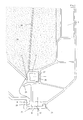
- Fig. 1 =
- Teilansicht der Entladungsklappe 1 mit der Betätigungswelle 2 (oberer Teil)
- Fig. 2 =
- Teilansicht der Entladungsklappe 1 im Bereich der Auslaßöffnung (unterer Teil der Entladeklappe)
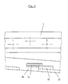
- Fig. 3 =
- Teilansicht im Seitenbereich der Siloauslaßöffnung
- Fig. 4 =
- Teilansicht in Richtung A gemäß Fig. 3 auf die Entladekappe 1 in verriegelter Stellung
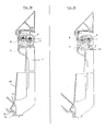
- Fig.5a bis 5d =
- Schematische Darstellungen des Bewegungsablaufes beim Öffnen der Entladeklappe bei leerem Silo
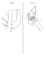
- Fig.6a bis 6d =
- Schematische Darstellungen des Bewegungsablaufes beim Öffnen der Entladeklappe bei beladenem Silo
- Gemäß Fig. 1 ist die Entladeklappe 1 über das Tür-Klappenlager 5 und Exzenter 3 mit der Betätigungswelle 2 verbunden. Die Verbindungslinie zwischen Drehmittelpunkt der Betätigungswelle 2 und Drehmittelpunkt der Achse 4 weist eine positive Steigung alpha in Richtung Siloinnenraum 16 auf. Der Exzenter 3 weist zur Entladeklappe 1 hin einen Schenkel 11 mit Anschlagfläche 7 auf. Das gegenüberliegende Teil der Entladeklappe 1 zeigt einen Puffer 14 sowie Verriegelungsprofile 12, 13.
- Oberhalb der Verbindungslinie der Drehmittelpunkte von Achse 4 und Betätigungswelle 2 ist an dem Klappenlager 5 eine Anlagefläche 6 angeordnet, die sich beim Drehen der Betätigungswelle 2 nach dem Entriegeln gegen die Welle 2 anlegt. Einschwenkbare Entriegelungshaken 20, 21 sind an dem Klappenlager 5 einerseits und an einem Profillappen 22 andererseits angeordnet. Mit 18 ist die Silokante und mit 27 sind spezielle Dichtpasten bzw. Klebebänder bezeichnet.
- Der untere Teil der Entladeklappe 1 und des Silos 16 sind in Fig. 2 dargestellt. Man erkennt die Unterkante (17) der Auslauföffnung, ein Dichtungsprofil 23 sowie Abweis- bzw. Abtropfkanten 24, 28. Die Klappenanlagekante 8 steht im Eingriff mit der Verriegelungskante 19 der Entladeklappe 1, die über ein Verriegelungsprofil 9 und Dichtpasten bzw. Klebebänder 27 mit der Entladeklappe 1 verschraubt ist. In dem Verriegelungsprofil 9 sind Ausfräsungen 25 eingebracht.
- In Fig. 3 u. 4 ist die seitliche Verriegelung der Entladeklappe 1 dargestellt, dies geschieht über Verhakungen 31, 32, 33, die einerseits an den vertikalen Silokanten 29 und andererseits an der Entladeklappe 1 angebracht sind. Ferner ist die Dichtung 30 mit einer Dichtpaste 27 im geschlossenen Zustand der Entladeklappe dargestellt.
- Der Bewegungsablauf beim Öffnen der Entladeklappe 1 und leerem Silo verläuft gem. Fig. 5 wie folgt:
- a) Klappe ist beschlossen und verriegelt,
- b) beim Drehen der Betätigungswelle 2 wird die Klappe 1 abgesenkt,
- c) nach weiterer Drehung der Betätigungswelle 2 wird die Verriegelung freigegeben und die Klappe durch das Antriebsmoment der Betätigungswelle 2 aufgeschwenkt,
- d) die aufgeschwenkte Entladungsklappe wird über die Betätigungswelle in der offenen Position gehalten.
- Der schematische Bewegungsablauf beim Öffnen der Entladungsklappe im beladenen Zustand des Silos 16 erfolgt gemäß Fig. 6 in der Reihenfolge:
- a) Klappe ist geschlossen und verriegelt,
- b) die Betätigungswelle 2 wird gedreht und die Klappe 1 abgesenkt,
- c) nach weiterer Drehung der Betätigungswelle 2 wird die Verriegelung freigegeben und die Entladungsklappe 1 durch Ladungsdruck aufgeschwenkt bis zum Anschlag der Flächen 7 und 14 (Fig. 1),
- d) das weitere Öffnen erfolgt durch Drehen der Betätigungswelle 2 mit Unterstützung durch Ladungskräfte. Endposition gem. Fig. 5d.
- Bevorzugt ist die einteilige Entladeklappe 1 über mehrere Klappenlager 5 an der Betätigungswelle 2 exzentrisch im bezug auf die durch den Drehmittelpunkt verlaufende horizontale Mittellinie angebrachten Achsen 4 drehbar gelagert. Durch Drehung der Betätigungswelle 2 mit aufgesetztem Exzenter 3 um insgesamt 45 Grad wird eine kombinierte Senk-Schwenkbewegung ausgeführt. Zu Beginn der Öffnungsbewegung erfolgt eine abwärtsgerichtete Vertikalbewegung der Klappenunterkante bis die durchlaufende Verriegelungskante 19 der Entladungsklappe gegenüber der Klappenanlagekante 8 frei wird. Die Fortsetzung der Drehbewegungen der Betätigungswelle 2 richtet sich nach dem Beladungszustand des Siloinnenraums 16.
- Die Betätigungswelle wird weiter gedreht, bis der Fortsatz des Klappenlagers 5 mit seiner Anlagefläche 6 an der Betätigungswelle 2 anliegt. Bei weiterer Drehung entsteht am Klappenlager 5 ein Drehmoment, das die Entladeklappe 1 aufschwenkt bzw. in Endposition offen hält (Fig. 5b, d).
- Nach Freiwerden der Verriegelung 8, 19 wird die Entladeklappe 1 durch die von der Ladung her ausgeübte Kraft um einige Winkelgrade bis zur Anlage des Puffers 14 an die Anschlagfläche 7 des Schenkels 11 des Exzenters 3 aufgeschwenkt (Fig. 6c).
- Die Betätigungswelle 2 wird - während der Ladungsdruck nachläßt - weiter gedreht bis sich die Flächen 7 und 14 voneinander entfernen und schließlich die Endposition nach Fig. 5d erreicht wird, in der die Klappe bis zur vollständigen Leerung des Silos offengehalten wird.
- Zum Schließen der Entladeklappe bei entleertem Silo wird die Betätigungswelle 2 zurückgedreht, wobei die Anlagefläche 6 an der Betätigungswelle 2 aufgrund des Eigengewichtes der Entladeklappe 1 angedrückt bleibt, bis die Dichtgummiprofile 23,30 und damit die Entladeklappe 1 an den entsprechenden Silokanten 17, 18 bzw. 29 anliegt.
- Je nach der notwendigen Andrückkraft gegen die Dichtgummis und der Schwerkraftkomponente der Entladeklappe in Schließrichtung ist des vorteilhaft, zusätzliche Schließfedern, wie Z.B. Schenkel- oder Drehfedern zwischen den Achsen 4 und dem Klappenlagern 5 vorzusehen. Dadurch wird ein Andrücken der Entladeklappe 1 bewirkt und das ordnungsgemäße Ineinandergreifen der Verriegelungshaken 20, 21, 8, 19, 31, 32 sichergestellt.
- Während der verbleibenden Drehbewegung hebt die Anlagefläche 6 von der Betätigungswelle 2 ab. Die Klappe wird durch eine Hubbewegung verriegelt. In der Ruhestellung der geschlossenen Entladeklappe liegt die Mittellinie der exzentrisch angeordneten Achsen 4 etwas oberhalb der Mittellinie der Betätigungswelle 2, dadurch wird eine Selbstsicherung gegen unbeabsichtigtes Öffnen bewirkt, denn bei auftretenden Ladungskräften entsteht ein Drehmoment um die Betätigungswelle 2, das in Schließrichtung der Entladeklappe 1 wirkt.
- Zusätzlich zu der durchlaufenden Verriegelung und Abdichtung an der Silounterkante gibt es bei der erfindungsgemäßen Lösung auch an der oberen horizontalen Abschlußkante der Entladeklappe 1 eine Verhakung 20, 21 in Verbindung mit dem Profillappen 22 und auch an den vertikalen Silokanten 29 eine Verhakung 31, 32, 33 in Verbindung mit den Dichtungen 30. Da die seitlichen Verhakungen nur örtlich sind, ist je nach Klappenhöhe eine entsprechende Anzahl zu wählen. Damit wird die Klappe ringsherum gehalten und abgedichtet, d.h. eine Spaltbildung bei Ladungsdruck und damit Undichtigkeit ausgeschlossen.
- Die Entladeklappe 1 besteht vorzugsweise aus Aluminiumstrangpreßprofilen, während das Klappenlager 5, die Dichtgummirückseiten 35, das Verriegelungsprofil 9 und die Nutensteine 12 in den Nuten 13 vorzugsweise aus Stahl gefertigt sind. Beim Zusammenbau der Aluminium- und Stahlteile sind direkter Kontakt der Einzelteile sowie Spalte durch eine Isolier- und Dichtpaste 27 oder durch spezielle Klebebänder zu vermeiden. Dadurch kann die Kontakt- und Spaltkorrosion weitgehend unterbunden werden.
- In Fig. 2 ist eine besondere Ausführungsform der Entladeklappe 1 dargestellt, sie weist Profilfahnen 24 auf, die als Abweiser für Schüttgut beim Öffnen der Entladeklappe 1 dienen, um ein Volllaufen des U-förmigen Verriegelungsprofils 9 zu vermeiden. Zusätzlich können in das Verriegelungsprofil 9 abschnittsweise Ausfräsungen eingebracht werden, um eingedrungene Fremdkörper oder Wasser aus dem Verriegelungsbereich zu entfernen. Die ebenfalls in Fig. 2 dargestellten Profillappen 28 dienen als Abtropfkante gegen Regenwasser.
Claims (5)
- Verriegelbare Tür, Klappe o.dgl. für stationäre oder mobile Silos, die insbesondere mit rieselfähigem Schüttgut beladen sind, mit wenigstens einer Auslauföffnung, die am unteren Ende eine Anlagekante (8) aufweist, gegen die eine an mindestens einem Tür-Klappenlager (5) befestigte Entladeklappe (1) angreift, dadurch gekennzeichnet, daß das obere Ende der Entladeklappe (1) exzentrisch über das Tür-Klappenlager (5) mit einer Achse (4) an einer Betätigungswelle (2) gelagert ist, wobei die Verbindungslinie zwischen Drehmittelpunkt der Achse (4) und Drehmittelpunkt der Betätigungswelle (2) im geschlossenen Zustand der Entladeklappe (1) eine positive Steigung von 2 bis 10 Grad zum Siloinnenraum hin aufweist und das Klappenlager (5) oberhalb der Verbindungslinie eine Anlagefläche (6) aufweist, die sich in der entriegelten Stellung der Entladeklappe (1) in Kontakt mit der Betätigungswelle (2) befindet
und der Exzenter (3) zur Entladeklappe (1) hin einen Schenkel (11) aufweist, der mit seiner Anschlagfläche (7) in Schließrichtung der Betätigungswelle (2) gegen einen an der Entladeklappe (1) befestigten Puffer (14) drückt. - Verriegelbare Tür-, Klappe o.dgl. nach Anspruch 1, dadurch gekennzeichnet, daß das Tür-Klappenlager (5) zum Siloinnenraum hin im verriegelten Zustand mit einem Profillappen (22) abgedeckt ist.
- Tür-, Klappe o.dgl. nach einem der vorhergehenden Ansprüche, dadurch gekennzeichnet, daß der Profillappen (22) einen Verriegelungshaken (20) aufweist, der in einen entsprechend ausgebildeten Gegenhaken (21) des Tür-Klappenlagers (5) eingreift.
- Tür-, Klappe o.dgl. nach einem der vorhergehenden Ansprüche, dadurch gekennzeichnet, daß die Entladeklappe (1) aus Aluminium oder einer Aluminiumlegierung besteht, wobei am unteren Ende der Entladeklappe (1) zur Anlagekante (8) hin ein Stahlprofil (9) angeordnet ist und die Stoßstelle zwischen Stahlprofil (9) und Entladeklappe (1) mit einer Abtropfkante (28) abgedeckt ist.
- Tür-, Klappe o.dgl. nach einem der vorhergehenden Ansprüche, dadurch gekennzeichnet, daß die Entladeklappe (1) eine Rundumverriegelung aufweist mit einer durchlaufenden Verriegelungskante (19) an der unteren Seite der Anlagekante (8), mit einschwenkbaren Verriegelungshaken (20,21) am oberen Ende in der Nähe des Klappenlagers (5) und einschiebbaren Verhakungen (31,32,33), die aus keilförmigen Abschnitten bestehen und an den Seitenflächen der Entladeklappe (1) bzw. der Siloseitenwand (34) befestigt sind.
Priority Applications (1)
| Application Number | Priority Date | Filing Date | Title |
|---|---|---|---|
| AT88117195T ATE80354T1 (de) | 1988-07-16 | 1988-10-15 | Verriegelbare tuer, klappe o.dgl. |
Applications Claiming Priority (2)
| Application Number | Priority Date | Filing Date | Title |
|---|---|---|---|
| DE3824216 | 1988-07-16 | ||
| DE3824216A DE3824216A1 (de) | 1988-07-16 | 1988-07-16 | Entladeklappe fuer rieselfaehiges schuettgut |
Publications (3)
| Publication Number | Publication Date |
|---|---|
| EP0351449A2 EP0351449A2 (de) | 1990-01-24 |
| EP0351449A3 EP0351449A3 (en) | 1990-10-17 |
| EP0351449B1 true EP0351449B1 (de) | 1992-09-09 |
Family
ID=6358860
Family Applications (1)
| Application Number | Title | Priority Date | Filing Date |
|---|---|---|---|
| EP88117195A Expired - Lifetime EP0351449B1 (de) | 1988-07-16 | 1988-10-15 | Verriegelbare Tür, Klappe o.dgl. |
Country Status (5)
| Country | Link |
|---|---|
| EP (1) | EP0351449B1 (de) |
| AT (1) | ATE80354T1 (de) |
| DE (2) | DE3824216A1 (de) |
| ES (1) | ES2034095T3 (de) |
| GR (1) | GR3006455T3 (de) |
Families Citing this family (2)
| Publication number | Priority date | Publication date | Assignee | Title |
|---|---|---|---|---|
| AT403686B (de) * | 1993-05-07 | 1998-04-27 | Zellinger Gmbh | Betätigungsvorrichtung für den aufklappbaren bodendeckel eines transportbehälters |
| CN114410319A (zh) * | 2021-12-23 | 2022-04-29 | 河北华丰能源科技发展有限公司 | 一种熄焦车的封门装置 |
Citations (1)
| Publication number | Priority date | Publication date | Assignee | Title |
|---|---|---|---|---|
| US2837040A (en) * | 1952-12-17 | 1958-06-03 | Youngstown Steel Door Co | Hatch frame and cover for covered hopper car |
Family Cites Families (4)
| Publication number | Priority date | Publication date | Assignee | Title |
|---|---|---|---|---|
| FR1118654A (fr) * | 1955-02-03 | 1956-06-08 | Charnière de porte | |
| GB1062911A (en) * | 1963-08-02 | 1967-03-22 | Horsfield & Co Ltd R | Installation for conveying,bunkering and discharging coal and other bulk materials |
| AR212043A1 (es) * | 1976-07-06 | 1978-04-28 | Bake W | Unidad para el traslado de los componentes dosificados y separados,necesarios para producir"in situ"cargas de hormigon |
| US4747742A (en) * | 1986-09-22 | 1988-05-31 | Swiss Aluminium Ltd. | Unloading flap for pourable particulate material |
-
1988
- 1988-07-16 DE DE3824216A patent/DE3824216A1/de not_active Withdrawn
- 1988-10-15 EP EP88117195A patent/EP0351449B1/de not_active Expired - Lifetime
- 1988-10-15 ES ES198888117195T patent/ES2034095T3/es not_active Expired - Lifetime
- 1988-10-15 AT AT88117195T patent/ATE80354T1/de not_active IP Right Cessation
- 1988-10-15 DE DE8888117195T patent/DE3874528D1/de not_active Expired - Lifetime
-
1992
- 1992-12-04 GR GR920402141T patent/GR3006455T3/el unknown
Patent Citations (1)
| Publication number | Priority date | Publication date | Assignee | Title |
|---|---|---|---|---|
| US2837040A (en) * | 1952-12-17 | 1958-06-03 | Youngstown Steel Door Co | Hatch frame and cover for covered hopper car |
Also Published As
| Publication number | Publication date |
|---|---|
| GR3006455T3 (de) | 1993-06-21 |
| EP0351449A3 (en) | 1990-10-17 |
| EP0351449A2 (de) | 1990-01-24 |
| ATE80354T1 (de) | 1992-09-15 |
| DE3824216A1 (de) | 1990-01-18 |
| DE3874528D1 (de) | 1992-10-15 |
| ES2034095T3 (es) | 1993-04-01 |
Similar Documents
| Publication | Publication Date | Title |
|---|---|---|
| DE60003193T2 (de) | Frachtcontainer | |
| DE2809375A1 (de) | Lastkraftwagen mit ladepritsche und aufbau | |
| DE2501798A1 (de) | Schwenkbare lastwagenklappe | |
| DE2915743A1 (de) | Deckelanordnung fuer einen behaelter, insbesondere lukenabdeckung fuer schiffe | |
| DE3905870C2 (de) | ||
| DE20117346U1 (de) | Ladewagen mit Entladungseinrichtung | |
| EP0351449A2 (de) | Verriegelbare Tür, Klappe o.dgl. | |
| EP1843909A1 (de) | Vorrichtung zum überführen der wand eines transportbehälters zwischen einer schliessstellung und einer offenstellung und transportbehälter | |
| DE1605012C3 (de) | Fahrzeug, insbesondere Eisenbahnwagen mit aufklappbarem Dach | |
| DE60306545T2 (de) | Behälter für schüttgut und transportsystem | |
| EP0262094B1 (de) | Entladeklappe für rieselfähiges Schüttgut | |
| DE3875086T2 (de) | Mehrzweck-container. | |
| EP0560152B1 (de) | Auf stirnwandseitigen Tragarmen abgestütztes Schwenkdach für Eisenbahngüterwagen | |
| EP0319665B1 (de) | Behälter | |
| EP0547448B1 (de) | Fahrzeug oder Behälter, insbesondere Eisenbahngüterwagen | |
| DE102022120671B3 (de) | Nutzfahrzeug-Laderaum mit Wetterschutzeinrichtung, Nutzfahrzeugzug und Verfahren zum Betätigen einer Wetterschutzeinrichtung | |
| DE102010020271B4 (de) | Gedeckter Güterwagen | |
| EP2196373B1 (de) | Klappenverschluss | |
| DE1964814B2 (de) | Schiebewand für Fahrzeuge, insbe sondere Eisenbahnguterwagen | |
| DE3107715C2 (de) | Verriegelung für eine Abrollsicherung einer Ladebordwand | |
| EP2048025A1 (de) | Schüttgut-Nutzfahrzeug | |
| DE1940611A1 (de) | Transportbehaelter | |
| DE9409607U1 (de) | Abrollbehälter oder -pritsche | |
| DE8120153U1 (de) | "Behälter insbesondere zum Transport auf für die Halterung von Containern ausgebildeten Ladepritschen von Lastkraftwagen, Angängern od.dgl." | |
| DE202022104643U1 (de) | Nutzfahrzeug-Laderaum mit Wetterschutzeinrichtung und Nutzfahrzeugzug |
Legal Events
| Date | Code | Title | Description |
|---|---|---|---|
| PUAI | Public reference made under article 153(3) epc to a published international application that has entered the european phase |
Free format text: ORIGINAL CODE: 0009012 |
|
| AK | Designated contracting states |
Kind code of ref document: A2 Designated state(s): AT BE CH DE ES FR GB GR IT LI LU NL SE |
|
| PUAL | Search report despatched |
Free format text: ORIGINAL CODE: 0009013 |
|
| AK | Designated contracting states |
Kind code of ref document: A3 Designated state(s): AT BE CH DE ES FR GB GR IT LI LU NL SE |
|
| 17P | Request for examination filed |
Effective date: 19910320 |
|
| 17Q | First examination report despatched |
Effective date: 19920207 |
|
| GRAA | (expected) grant |
Free format text: ORIGINAL CODE: 0009210 |
|
| RAP1 | Party data changed (applicant data changed or rights of an application transferred) |
Owner name: VAW ALUMINIUM AG |
|
| AK | Designated contracting states |
Kind code of ref document: B1 Designated state(s): AT BE CH DE ES FR GB GR IT LI LU NL SE |
|
| REF | Corresponds to: |
Ref document number: 80354 Country of ref document: AT Date of ref document: 19920915 Kind code of ref document: T |
|
| GBT | Gb: translation of ep patent filed (gb section 77(6)(a)/1977) | ||
| REF | Corresponds to: |
Ref document number: 3874528 Country of ref document: DE Date of ref document: 19921015 |
|
| ET | Fr: translation filed | ||
| ITF | It: translation for a ep patent filed | ||
| REG | Reference to a national code |
Ref country code: ES Ref legal event code: FG2A Ref document number: 2034095 Country of ref document: ES Kind code of ref document: T3 |
|
| REG | Reference to a national code |
Ref country code: GR Ref legal event code: FG4A Free format text: 3006455 |
|
| PLBE | No opposition filed within time limit |
Free format text: ORIGINAL CODE: 0009261 |
|
| STAA | Information on the status of an ep patent application or granted ep patent |
Free format text: STATUS: NO OPPOSITION FILED WITHIN TIME LIMIT |
|
| 26N | No opposition filed | ||
| PGFP | Annual fee paid to national office [announced via postgrant information from national office to epo] |
Ref country code: GB Payment date: 19930927 Year of fee payment: 6 |
|
| PGFP | Annual fee paid to national office [announced via postgrant information from national office to epo] |
Ref country code: LU Payment date: 19931015 Year of fee payment: 6 |
|
| PGFP | Annual fee paid to national office [announced via postgrant information from national office to epo] |
Ref country code: GR Payment date: 19931027 Year of fee payment: 6 |
|
| PGFP | Annual fee paid to national office [announced via postgrant information from national office to epo] |
Ref country code: ES Payment date: 19931028 Year of fee payment: 6 |
|
| PGFP | Annual fee paid to national office [announced via postgrant information from national office to epo] |
Ref country code: NL Payment date: 19931031 Year of fee payment: 6 |
|
| PGFP | Annual fee paid to national office [announced via postgrant information from national office to epo] |
Ref country code: BE Payment date: 19931105 Year of fee payment: 6 |
|
| EPTA | Lu: last paid annual fee | ||
| PG25 | Lapsed in a contracting state [announced via postgrant information from national office to epo] |
Ref country code: LU Free format text: LAPSE BECAUSE OF NON-PAYMENT OF DUE FEES Effective date: 19941015 Ref country code: GB Effective date: 19941015 |
|
| PG25 | Lapsed in a contracting state [announced via postgrant information from national office to epo] |
Ref country code: ES Free format text: LAPSE BECAUSE OF EXPIRATION OF PROTECTION Effective date: 19941017 |
|
| PG25 | Lapsed in a contracting state [announced via postgrant information from national office to epo] |
Ref country code: BE Effective date: 19941031 |
|
| EAL | Se: european patent in force in sweden |
Ref document number: 88117195.3 |
|
| BERE | Be: lapsed |
Owner name: VAW ALUMINIUM A.G. Effective date: 19941031 |
|
| PG25 | Lapsed in a contracting state [announced via postgrant information from national office to epo] |
Ref country code: GR Free format text: THE PATENT HAS BEEN ANNULLED BY A DECISION OF A NATIONAL AUTHORITY Effective date: 19950430 |
|
| PG25 | Lapsed in a contracting state [announced via postgrant information from national office to epo] |
Ref country code: NL Effective date: 19950501 |
|
| GBPC | Gb: european patent ceased through non-payment of renewal fee |
Effective date: 19941015 |
|
| NLV4 | Nl: lapsed or anulled due to non-payment of the annual fee | ||
| REG | Reference to a national code |
Ref country code: GR Ref legal event code: MM2A Free format text: 3006455 |
|
| PGFP | Annual fee paid to national office [announced via postgrant information from national office to epo] |
Ref country code: FR Payment date: 19961016 Year of fee payment: 9 |
|
| PGFP | Annual fee paid to national office [announced via postgrant information from national office to epo] |
Ref country code: SE Payment date: 19961021 Year of fee payment: 9 Ref country code: AT Payment date: 19961021 Year of fee payment: 9 |
|
| PGFP | Annual fee paid to national office [announced via postgrant information from national office to epo] |
Ref country code: CH Payment date: 19961024 Year of fee payment: 9 |
|
| PGFP | Annual fee paid to national office [announced via postgrant information from national office to epo] |
Ref country code: DE Payment date: 19961221 Year of fee payment: 9 |
|
| PG25 | Lapsed in a contracting state [announced via postgrant information from national office to epo] |
Ref country code: AT Free format text: LAPSE BECAUSE OF NON-PAYMENT OF DUE FEES Effective date: 19971015 |
|
| PG25 | Lapsed in a contracting state [announced via postgrant information from national office to epo] |
Ref country code: SE Free format text: LAPSE BECAUSE OF NON-PAYMENT OF DUE FEES Effective date: 19971016 |
|
| PG25 | Lapsed in a contracting state [announced via postgrant information from national office to epo] |
Ref country code: LI Free format text: LAPSE BECAUSE OF NON-PAYMENT OF DUE FEES Effective date: 19971031 Ref country code: FR Free format text: THE PATENT HAS BEEN ANNULLED BY A DECISION OF A NATIONAL AUTHORITY Effective date: 19971031 Ref country code: CH Free format text: LAPSE BECAUSE OF NON-PAYMENT OF DUE FEES Effective date: 19971031 |
|
| REG | Reference to a national code |
Ref country code: CH Ref legal event code: PL |
|
| PG25 | Lapsed in a contracting state [announced via postgrant information from national office to epo] |
Ref country code: DE Free format text: LAPSE BECAUSE OF NON-PAYMENT OF DUE FEES Effective date: 19980701 |
|
| EUG | Se: european patent has lapsed |
Ref document number: 88117195.3 |
|
| REG | Reference to a national code |
Ref country code: FR Ref legal event code: ST |
|
| REG | Reference to a national code |
Ref country code: ES Ref legal event code: FD2A Effective date: 19990601 |
|
| PG25 | Lapsed in a contracting state [announced via postgrant information from national office to epo] |
Ref country code: IT Free format text: LAPSE BECAUSE OF NON-PAYMENT OF DUE FEES;WARNING: LAPSES OF ITALIAN PATENTS WITH EFFECTIVE DATE BEFORE 2007 MAY HAVE OCCURRED AT ANY TIME BEFORE 2007. THE CORRECT EFFECTIVE DATE MAY BE DIFFERENT FROM THE ONE RECORDED. Effective date: 20051015 |