EP0350631B1 - Heumaschine für Front- und Heckanbau an Schlepper - Google Patents
Heumaschine für Front- und Heckanbau an Schlepper Download PDFInfo
- Publication number
- EP0350631B1 EP0350631B1 EP89110682A EP89110682A EP0350631B1 EP 0350631 B1 EP0350631 B1 EP 0350631B1 EP 89110682 A EP89110682 A EP 89110682A EP 89110682 A EP89110682 A EP 89110682A EP 0350631 B1 EP0350631 B1 EP 0350631B1
- Authority
- EP
- European Patent Office
- Prior art keywords
- machine
- strut
- rear mounting
- frame structure
- machine frame
- Prior art date
- Legal status (The legal status is an assumption and is not a legal conclusion. Google has not performed a legal analysis and makes no representation as to the accuracy of the status listed.)
- Expired - Lifetime
Links
- 239000000945 filler Substances 0.000 description 1
Images

Classifications
-
- A—HUMAN NECESSITIES
- A01—AGRICULTURE; FORESTRY; ANIMAL HUSBANDRY; HUNTING; TRAPPING; FISHING
- A01D—HARVESTING; MOWING
- A01D78/00—Haymakers with tines moving with respect to the machine
- A01D78/08—Haymakers with tines moving with respect to the machine with tine-carrying rotary heads or wheels
- A01D78/10—Haymakers with tines moving with respect to the machine with tine-carrying rotary heads or wheels the tines rotating about a substantially vertical axis
- A01D78/1071—Having only one rotor
-
- A—HUMAN NECESSITIES
- A01—AGRICULTURE; FORESTRY; ANIMAL HUSBANDRY; HUNTING; TRAPPING; FISHING
- A01D—HARVESTING; MOWING
- A01D67/00—Undercarriages or frames specially adapted for harvesters or mowers; Mechanisms for adjusting the frame; Platforms
- A01D67/005—Arrangements of coupling devices
Definitions
- the invention relates to a hay machine for front and rear attachment to tractors according to the features of the preamble of claim 1.
- a hay machine of this type is described for example in DE-B-32 23 768.
- the object of the invention is therefore to improve a generic machine so that it no longer has the shortcomings still attached to it, ie that it can be moved to a desired position laterally to the longitudinal axis of the tractor, if required, by means of a suitable adjusting device with simple and quick handling can be. This is achieved by an embodiment according to the characterizing features of claim 1.
- variable-length strut in a manner known per se consists of two telescopically displaceable partial struts which can be locked against one another in different positions by means of a latching device to be operated from the tractor seat, or optionally by unlocking are freely movable.
- the machine frame (8) carries at its front end a swivel head (9) which is penetrated by both the horizontal swivel pin (4) and the vetical swivel pin (7). As a result, the machine frame (8) can be pivoted about a transverse and a vertical axis relative to the three-point frame (2). At the rear end of the machine frame (8) there are a gyroscope (10) with controlled tines (11) and a chassis (12).
- variable-length strut (15) is clamped, which consists of a front part strut (16), a rear part strut (17) and a locking device (18).
- the locking device (18) has a rotatably mounted angle lever (19) which is operatively connected to a vertical locking bolt (20). When a cable (21) leading to the tractor is pulled, the angle lever (19) moves the locking bolt (20) upwards into a lockable position, whereby the partial struts (16), (17) can be displaced relative to one another.
- the locking bolt (20) passes through bores (22) in the partial struts (16), (17) under the action of a spring (not shown) and thereby locks them in the desired length.
- the vertical swivel pin (7) can move freely within its elongated hole (6).
- the machine frame (8) can then turn around the horizontal pivot pin (4).
- This flexibility must be switched off when mounting on the front.
- a filler piece (24) attached to an angle lever (23) is pivoted into the elongated hole (6).
- the angle lever (23) can be fixed in two positions by means of a plug pin (25).
- the locking pin (20) When attaching the hay machine to the rear, the locking pin (20) is locked in a raised position.
- the partial struts (16), (17) can move against each other and the machine can, for example, turn around the vertical pivot pin (7) relative to the tractor.
- the locking pin (20) When attaching the hay machine to the front, the locking pin (20) is in a lower position under the action of a spring and thereby penetrates a bore (22) in the rear part strut (17) and at the same time a freely selected bore (22) in the front partial strut (16). This means that the hay machine can be driven either in the direction of travel or at an angle.
Landscapes
- Life Sciences & Earth Sciences (AREA)
- Environmental Sciences (AREA)
- Agricultural Machines (AREA)
- Soil Working Implements (AREA)
- Details Of Connecting Devices For Male And Female Coupling (AREA)
Description
- Die Erfindung bezieht sich auf eine Heumaschine für Front- und Heckanbau an Schlepper nach den Merkmalen des Oberbegriffes des Anspruches 1. Eine Heumaschine dieser Art ist zum Beispiel in der DE-B-32 23 768 beschrieben.
- Bei Maschinen dieser Ausführung ist mit einer Feststellung des Maschinengestells in seiner Querachse zwangsläufig auch dessen Feststellung in seiner Hochachse verbunden. Die Maschine kann somit im Frontanbau nicht seitlich zur Schlepperlängsachse versetzt werden, um mit ihr Feldgrenzen (z. B. Zäune oder Gräben) von Erntegut freizuräumen oder bei breiten Schleppern ein Überfahren des ablaufenden Schwades von den Schlepperrädern zu vermeiden.
- Die Aufgabe der Erfindung ist es daher, eine gattungsgemäße Maschine so zu verbessern, daß sie die ihr noch anhaftenden Mängel nicht mehr aufweist, d.h., daß sie bei Erfordernis durch eine geeignete Stellvorrichtung mit einfacher und schneller Handhabung in eine jeweils gewünschte Lage seitlich zur Schlepperlängsachse versetzt werden kann. Dies wird durch eine Ausführung nach den kennzeichnenden Merkmalen des Patentanspruches 1 erreicht.
- Nach einem weiteren Merkmal der Erfindung besteht die längenveränderliche Strebe in an sich (beispw. aus der DE-A-2909774) bekannten Weise aus zwei teleskopartig verschiebbaren Teilstreben, die mittels einer vom Schleppersitz aus zu betätigenden Rastvorrichtung in verschiedenen Stellungen gegeneinander verriegelbar oder wahlweise durch Entriegelung frei verschiebbar sind.
- Die Erfindung wird am Beispiel einer Kreiselheumaschine dargestellt und erläutert.
- Fig. 1
- zeigt eine Kreiselheumaschine, die an das vordere oder hintere Dreipunktgestänge eines Schleppers angebaut ist in Seitenansicht,
- Fig. 2
- zeigt den gleichen Gegenstand in Draufsicht
- Fig. 3
- zeigt einen Dreipunktrahmen in Rückansicht
- Fig. 4
- zeigt den gleichen Gegenstand in Draufsicht
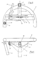
- Das Maschinengestell (8) trägt an seinem vorderen Ende einen Schwenkkopf (9), der sowohl von dem horizontalen Schwenkbolzen (4), als auch von dem vetikalen Schwenkbolzen (7) durchsetzt wird. Dadurch ist das Maschinengestell (8) zu dem Dreipunktrahmen (2) um eine Quer- und eine Hochachse schwenkbar. Am rückwärtigen Ende des Maschinengestelles (8) sind ein Arbeitskreisel (10) mit gesteuerten Zinken (11) und ein Fahrwerk (12) gelagert.
- Zwischen einem Gelenkpunkt (13) am Dreipunktrahmen (2) und einem Gelenkpunkt (14) am rückwärtigen Ende des Maschinengestelles (8) ist eine längenveränderliche Strebe (15) eingespannt, die aus einer vorderen Teilstrebe (16), einer hinteren Teilstrebe (17) und einer Rastvorrichtung (18) besteht. Die Rastvorrichtung (18) hat einen drehbar gelagerten Winkelhebel (19), der mit einem senkrechten Rastbolzen (20) in Wirkverbindung steht. Wenn an einem zum Schlepper führenden Seilzug (21) gezogen wird, bewegt der Winkelhebel (19) den Rastbolzen (20) nach oben in eine arretierbare Lage, wodurch die Teilstreben (16), (17) gegeneinander verschiebbar werden.
- Bei losgelassenem Seilzug (21) durchsetzt der Rastbolzen (20) unter der Wirkung einer nicht dargestellten Feder Bohrungen (22) in den Teilstreben (16), (17) und arretiert sie dadurch in der gewünschten Länge.
- Beim Heckanbau der Heumaschine kann sich der vertikale Schwenkbolzen (7) in dem von ihm durchsetzten Langloch (6) in dessen Grenzen frei bewegen. Das Maschinengestell (8) kann sich dann um den horizontalen Schwenkbolzen (4) drehen . Beim Frontanbau muß diese Beweglichkeit ausgeschaltet werden. Zu diesem Zweck wird ein an einem Winkelhebel (23) befestigtes Füllstück (24) in das Langloch (6) eingeschwenkt. Dadurch kann sich der vertikale Schwenkbolzen (7) nicht mehr frei in dem Langloch (6) bewegen. Die Höhenanpassung der Maschine geschieht jetzt über einen Freigang des Dreipunktgestänges (1). Der Winkelhebel (23) kann durch einen Steckbolzen (25) in zwei Lagen festgelegt werden.
- Beim Heckanbau der Heumaschine wird der Rastbolzen (20) in einer hochgehobenen Stellung arretiert. Die Teilstreben (16), (17) können sich gegeneinander verschieben und die Maschine kann sich zum Beispiel in der Kurve relativ zum Schlepper um den vertikalen Schwenkbolzen (7) drehen. Beim Frontanbau der Heumaschine steht der Rastbolzen (20) unter Wirkung einer Feder in einer unteren Lage und durchsetzt dabei eine Bohrung (22) in der hinteren Teilstrebe (17) und gleichzeitig eine frei gewählte Bohrung (22) in der vorderen Teilstrebe (16). Dadurch kann die Heumaschine wahlweise in Fahrtrichtung oder schräg dazu gefahren werden.
Claims (2)
- Heumaschine für Front- und Heckanbau an Schlepper mit einem, um eine Hoch- (7) und eine Querachse (4) pendelbar mit einem Dreipunktrahmen (2) verbundenen Maschinengestell (8), das im Heckanbau in Arbeitsstellung frei schwenkbar ist, in Transportstellung aber in beiden Achsen festgestellt ist und im Frontanbau sowohl in der Arbeitsstellung, als auch in der Transportstellung in beiden Achsen festgestellt ist, gekennzeichnet durch die Kombination folgender. Merkmale:a) Das Maschinengestell (8) ist nach Feststellung in seiner Querachse (4) weiter um die Hochachse (7) pendelbar,b) zur Feststellung des Maschinengestelles (8) in seiner Querachse (4) ist ein mittels einer Hebelvorrichtung (23) in ein, das untere Ende des vertikalen Schwenkbolzens (7) aufnehmendes Langloch (6) am Dreipunktrahmen (2) einbringbares Füllstück (24) vorgesehen,c) das Füllstück (24) ist für den Heckanbau der Maschine durch die Hebelvorrichtung (23) aus dem Langloch (6) ausbring- und feststellbar,d) die Vorrichtung zur Feststellung des Maschinengestelles (8) um die als vertikalen Schwenkbolzen (7) ausgebildete Hochachse (7) für den Frontanbau der Maschine ist eine in ihrer Länge durch eine Rastvorrichtung (18) wahlweise einstellbare Strebe (15) zwischen Maschinengestell (8) und Dreipunktrahmen (2),e) die Strebe (15) ist für den Heckanbau der Maschine durch Lösen der Rastvorrichtung (18) in ihrer Länge frei veränderlich.
- Heumaschine nach Anspruch 1, dadurch gekennzeichnet, daß die längenveränderliche Strebe (15) in an sich bekannter Weise aus zwei teleskopartig verschiebbaren Teilstreben (16, 17) besteht, die mittels einer vom Schleppersitz aus zu betätigenden Rastvorrichtung (18) in verschiedenen Stellungen gegeneinander verriegelbar oder wahlweise durch Entriegelung frei verschiebbar sind.
Priority Applications (1)
| Application Number | Priority Date | Filing Date | Title |
|---|---|---|---|
| AT89110682T ATE83601T1 (de) | 1988-07-09 | 1989-06-13 | Heumaschine fuer front- und heckanbau an schlepper. |
Applications Claiming Priority (2)
| Application Number | Priority Date | Filing Date | Title |
|---|---|---|---|
| DE8808847U | 1988-07-09 | ||
| DE8808847U DE8808847U1 (de) | 1988-07-09 | 1988-07-09 | Heumaschine für Front- und Heckanbau an Schlepper |
Publications (2)
| Publication Number | Publication Date |
|---|---|
| EP0350631A1 EP0350631A1 (de) | 1990-01-17 |
| EP0350631B1 true EP0350631B1 (de) | 1992-12-23 |
Family
ID=6825836
Family Applications (1)
| Application Number | Title | Priority Date | Filing Date |
|---|---|---|---|
| EP89110682A Expired - Lifetime EP0350631B1 (de) | 1988-07-09 | 1989-06-13 | Heumaschine für Front- und Heckanbau an Schlepper |
Country Status (3)
| Country | Link |
|---|---|
| EP (1) | EP0350631B1 (de) |
| AT (1) | ATE83601T1 (de) |
| DE (2) | DE8808847U1 (de) |
Families Citing this family (4)
| Publication number | Priority date | Publication date | Assignee | Title |
|---|---|---|---|---|
| DE4005288C2 (de) * | 1990-02-20 | 1999-12-16 | Claas Saulgau Gmbh | Kreiselheumaschine mit verriegelbaren Außenarmen |
| DE4019077A1 (de) * | 1990-06-15 | 1991-12-19 | Claas Saulgau Gmbh | Schwenkvorrichtung fuer eine, an die dreipunktaufhaengung eines schleppers anbaubare landmaschine |
| DE4112155C1 (de) * | 1991-04-13 | 1992-07-30 | Friedrich Moertl Schleppergeraetebau Gmbh & Co Kg, 8780 Gemuenden, De | |
| DE9114315U1 (de) * | 1991-11-18 | 1992-02-06 | H. Niemeyer Söhne GmbH & Co KG, 4446 Hörstel | Heuwerbungsmaschine |
Family Cites Families (3)
| Publication number | Priority date | Publication date | Assignee | Title |
|---|---|---|---|---|
| DE2909774C2 (de) * | 1978-03-14 | 1985-03-28 | Patent Concern N.V., Willemstad, Curacao | Landwirtschaftliche Maschine, wie Heuwerbungs- oder Mähmaschine |
| DE3223768C2 (de) * | 1982-06-25 | 1985-08-29 | Claas Saulgau GmbH, 7968 Saulgau | An die Dreipunktaufhängung eines landw. Schleppers anschließbarer Kreiselschwader |
| DE3619045A1 (de) * | 1986-06-06 | 1987-12-10 | Stoll Maschf Gmbh Wilhelm | Heuwerbungsmaschine |
-
1988
- 1988-07-09 DE DE8808847U patent/DE8808847U1/de not_active Expired
-
1989
- 1989-06-13 AT AT89110682T patent/ATE83601T1/de not_active IP Right Cessation
- 1989-06-13 DE DE8989110682T patent/DE58903089D1/de not_active Expired - Fee Related
- 1989-06-13 EP EP89110682A patent/EP0350631B1/de not_active Expired - Lifetime
Also Published As
| Publication number | Publication date |
|---|---|
| DE58903089D1 (de) | 1993-02-04 |
| DE8808847U1 (de) | 1988-09-29 |
| EP0350631A1 (de) | 1990-01-17 |
| ATE83601T1 (de) | 1993-01-15 |
Similar Documents
| Publication | Publication Date | Title |
|---|---|---|
| DE2715375B2 (de) | Stellvorrichtung für ein landwirtschaftlich nutzbares Arbeitsgerät | |
| EP0016317B1 (de) | Höhenverstellbare Anhängerkupplung | |
| EP0792574A1 (de) | Gezogenes Gerät | |
| EP0063774A1 (de) | Geräteanbauvorrichtung für ein landwirtschaftliches Arbeitsfahrzeug | |
| EP0567960B1 (de) | Anhängevorrichtung zum Ziehen eines ersten und eines zweiten Gerätes | |
| EP0388801A2 (de) | Hydraulisch betätigbare Hubvorrichtung | |
| DE3401631C2 (de) | ||
| DE4114580C2 (de) | Landwirtschaftliche Maschine mit veränderbarer Arbeitsbreite | |
| DE3530107C2 (de) | Pflug | |
| DE1632776A1 (de) | Rahmen fuer Dreipunktanhaengung von landwirtschaftlichen Arbeitsmaschinen an einen Schlepper | |
| DE4339323B4 (de) | Drehpflug mit seitlichem Pendelstützrad | |
| AT402249B (de) | Heuwerbungsmaschine | |
| DE8413456U1 (de) | Maehwerk | |
| EP0068381B1 (de) | Von einem Ackerschlepper nachgeschleppter Pflug | |
| EP0155692A2 (de) | Landwirtschaftliche Maschine | |
| EP0350631A1 (de) | Heumaschine für Front- und Heckanbau an Schlepper | |
| DE4112155C1 (de) | ||
| DE2529928C2 (de) | Anbauvorrichtung für eine landwirtschaftliche Maschine | |
| DE2615497C3 (de) | Zugdeichselanordnung für schleppergezogene landwirtschaftliche Maschine | |
| EP0651938B1 (de) | Heuwerbungsmaschine | |
| EP0184155B1 (de) | Rotationsmähwerk | |
| DE2416316B2 (de) | Heuwerbungsmaschine | |
| DE8905240U1 (de) | Mähmaschine | |
| DE2015043A1 (de) | Bodenbearbeitungsgerät, insbeson dere Egge | |
| DE2648528C2 (de) | Anbaurahmen für landwirtschaftliche Geräte, wie Ackerwalzen, Krümlerwalzen, Sägeräte, Hackeinrichtungen u.ä. |
Legal Events
| Date | Code | Title | Description |
|---|---|---|---|
| PUAI | Public reference made under article 153(3) epc to a published international application that has entered the european phase |
Free format text: ORIGINAL CODE: 0009012 |
|
| 17P | Request for examination filed |
Effective date: 19891116 |
|
| AK | Designated contracting states |
Kind code of ref document: A1 Designated state(s): AT CH DE FR IT LI NL |
|
| 17Q | First examination report despatched |
Effective date: 19910214 |
|
| ITF | It: translation for a ep patent filed | ||
| GRAA | (expected) grant |
Free format text: ORIGINAL CODE: 0009210 |
|
| AK | Designated contracting states |
Kind code of ref document: B1 Designated state(s): AT CH DE FR IT LI NL |
|
| REF | Corresponds to: |
Ref document number: 83601 Country of ref document: AT Date of ref document: 19930115 Kind code of ref document: T |
|
| REF | Corresponds to: |
Ref document number: 58903089 Country of ref document: DE Date of ref document: 19930204 |
|
| ET | Fr: translation filed | ||
| PLBE | No opposition filed within time limit |
Free format text: ORIGINAL CODE: 0009261 |
|
| STAA | Information on the status of an ep patent application or granted ep patent |
Free format text: STATUS: NO OPPOSITION FILED WITHIN TIME LIMIT |
|
| 26N | No opposition filed | ||
| PGFP | Annual fee paid to national office [announced via postgrant information from national office to epo] |
Ref country code: DE Payment date: 19960625 Year of fee payment: 8 |
|
| PGFP | Annual fee paid to national office [announced via postgrant information from national office to epo] |
Ref country code: AT Payment date: 19960627 Year of fee payment: 8 |
|
| PGFP | Annual fee paid to national office [announced via postgrant information from national office to epo] |
Ref country code: NL Payment date: 19960630 Year of fee payment: 8 |
|
| PGFP | Annual fee paid to national office [announced via postgrant information from national office to epo] |
Ref country code: CH Payment date: 19960902 Year of fee payment: 8 |
|
| PG25 | Lapsed in a contracting state [announced via postgrant information from national office to epo] |
Ref country code: AT Effective date: 19970613 |
|
| PGFP | Annual fee paid to national office [announced via postgrant information from national office to epo] |
Ref country code: FR Payment date: 19970625 Year of fee payment: 9 |
|
| PG25 | Lapsed in a contracting state [announced via postgrant information from national office to epo] |
Ref country code: LI Free format text: LAPSE BECAUSE OF NON-PAYMENT OF DUE FEES Effective date: 19970630 Ref country code: CH Free format text: LAPSE BECAUSE OF NON-PAYMENT OF DUE FEES Effective date: 19970630 |
|
| PG25 | Lapsed in a contracting state [announced via postgrant information from national office to epo] |
Ref country code: NL Effective date: 19980101 |
|
| REG | Reference to a national code |
Ref country code: CH Ref legal event code: PL |
|
| NLV4 | Nl: lapsed or anulled due to non-payment of the annual fee |
Effective date: 19980101 |
|
| PG25 | Lapsed in a contracting state [announced via postgrant information from national office to epo] |
Ref country code: DE Free format text: LAPSE BECAUSE OF NON-PAYMENT OF DUE FEES Effective date: 19980303 |
|
| PG25 | Lapsed in a contracting state [announced via postgrant information from national office to epo] |
Ref country code: FR Free format text: LAPSE BECAUSE OF NON-PAYMENT OF DUE FEES Effective date: 19990226 |
|
| REG | Reference to a national code |
Ref country code: FR Ref legal event code: ST |
|
| PG25 | Lapsed in a contracting state [announced via postgrant information from national office to epo] |
Ref country code: IT Free format text: LAPSE BECAUSE OF NON-PAYMENT OF DUE FEES;WARNING: LAPSES OF ITALIAN PATENTS WITH EFFECTIVE DATE BEFORE 2007 MAY HAVE OCCURRED AT ANY TIME BEFORE 2007. THE CORRECT EFFECTIVE DATE MAY BE DIFFERENT FROM THE ONE RECORDED. Effective date: 20050613 |