EP0349995A2 - Procédé d'adaptation d'un chargeur de batterie à différents procédés de charge et types de batterie et chargeur - Google Patents
Procédé d'adaptation d'un chargeur de batterie à différents procédés de charge et types de batterie et chargeur Download PDFInfo
- Publication number
- EP0349995A2 EP0349995A2 EP89112225A EP89112225A EP0349995A2 EP 0349995 A2 EP0349995 A2 EP 0349995A2 EP 89112225 A EP89112225 A EP 89112225A EP 89112225 A EP89112225 A EP 89112225A EP 0349995 A2 EP0349995 A2 EP 0349995A2
- Authority
- EP
- European Patent Office
- Prior art keywords
- battery
- program module
- battery charger
- charging
- program
- Prior art date
- Legal status (The legal status is an assumption and is not a legal conclusion. Google has not performed a legal analysis and makes no representation as to the accuracy of the status listed.)
- Withdrawn
Links
Images

Classifications
-
- H—ELECTRICITY
- H02—GENERATION; CONVERSION OR DISTRIBUTION OF ELECTRIC POWER
- H02J—ELECTRIC POWER NETWORKS; CIRCUIT ARRANGEMENTS OR SYSTEMS FOR SUPPLYING OR DISTRIBUTING ELECTRIC POWER; SYSTEMS FOR STORING ELECTRIC ENERGY
- H02J7/00—Circuit arrangements for charging or discharging batteries or for supplying loads from batteries
- H02J7/485—Circuit arrangements for charging or discharging batteries or for supplying loads from batteries with provisions for charging different types of batteries
Definitions
- the invention relates to a method for adapting a battery charger to different charging methods and battery types.
- Battery chargers for rechargeable batteries work with a wide variety of charging methods. For example, methods with constant current or constant voltage or combinations of both are used.
- the increased use of low-maintenance, dry battery types, for example in battery-powered vehicles, requires this use of short and economical charging procedures that are precisely tailored to the relevant battery type.
- the subtle differences between the individual battery types essentially consist in the current and voltage values to be observed during the recharge phase.
- a precise adaptation to the respective battery type is particularly advantageous if the respective charging time has to be optimized taking into account the service life of a battery. For this purpose, when changing the charging method or the type of battery, a new battery charger or a very complex new change of the old battery charger was required.
- the battery charger can be easily adapted to different charging methods and battery types by exchanging a parameter associated with the battery charger and battery, charging method, charging time and / or use-dependent parameters and possibly one or more charging methods in program form.
- the battery charger according to the invention has an exchangeable program module which contains the aforementioned data (parameters, programs).
- the interchangeable program module advantageously has at least one or more memories in which charging methods, charging characteristics and / or predetermined target values can be stored. These memories are the heart of the program module. They contain all the essentials charging process-typical parameters, time profiles etc.
- the battery charger can be adapted to any type of battery and charging method.
- a new battery charger or time-consuming retrofitting of the old battery charger is no longer necessary.
- processor with further control and auxiliary circuits for controlling the charging process in the battery charger, but outside the program module.
- the component (program module) to be replaced to adapt to a new battery type or a new charging process is therefore particularly small.
- the program module is designed as a programmable memory module, in particular as an EPROM.
- the program module can be manufactured particularly inexpensively in this way.
- program modules that have already been programmed can be reprogrammed to adapt them to special customer requirements.
- a battery charger 10 is provided with control electronics 11, which monitors the charging process of a connected battery 12.
- a program module 13 supplies charging process and battery-dependent information to the control electronics 11 and is plugged onto the latter (cf. FIG. 2).
- the program module 13 is exchanged accordingly by releasing a plug connection 14 in the area of the control electronics 11 and by inserting another program module.
- the control electronics 11 contains components, not shown in the figures, such as D / A converters, A / D converters, regulators, actuators and, if appropriate, display instruments.
- FIG. 3 shows another embodiment compared to FIG. 2, in which the program module 13 is connected to the battery 12, for example by a plug connection.
- the connection to the battery charger 10 is made via a signal line 16 parallel to the power connection 15.
- the program module 13 is connected to the battery due to the connection 12 always exchanged together with this and always supplies the control electronics 11 with the battery-specific information.
- the structure of the program module 13 is shown in FIG. 1.
- the essential components of the program module 13 are a program memory 17, a processor 18 and four potentiometers 19. .22.
- the program memory 17 contains all the important charging method-dependent and battery-typical data. It is designed as an erasable, programmable memory (EPROM).
- EPROM erasable, programmable memory
- the EPROM can be programmed according to the requirements and, if necessary, deleted and reprogrammed.
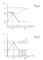
- FIGS. 4 and 5 show current and voltage as a function of time for different charging methods.
- the dashed line represents the voltage curve and the solid line represents the current curve over time.
- Characteristic voltage values during the charging process are the initial charge voltage U 1, the gassing voltage U 2 and the final charge voltage U 3. Accordingly, a distinction is made in the current between the initial charge current I 1 and the final charge current I 2.
- the charging process itself is divided into two phases, namely the main charging phase P1 and the reloading phase P2.
- the loading profiles shown in Figures 4 and 5 differ essentially in the reloading phase P2. These differences in the recharge phase P2 are usually caused by the use of different types of batteries, e.g. a gel battery as opposed to a wet battery.
- the program memory 17 accordingly contains all the information that is necessary to differentiate the different charging processes, such as the course of the current and the voltage over time.
- the voltage and current values mentioned are essentially battery-dependent and can be set by means of the potentiometers 19. 22 (according to FIG. 1), so that at Using the same charging method for similar batteries, only the potentiometers 19. .22 need to be adjusted and the program module 13 does not have to be replaced.
- the potentiometers 19. 22 are arranged on an end face 23 of the program module 13 and each have adjustment screws 24. 27. The latter are arranged so that they are accessible and adjustable from the outside even when the program module 13 is plugged onto the battery charger 10.
- the number of adjustable potentiometers depends on the number of current and voltage values to be set. For example, a maximum cell voltage before charging, a minimum cell voltage for the start of charging and a sulfation voltage could also be provided as changeable parameters. The number of potentiometers 19-22 would then have to be adjusted accordingly.
- a further component of the program module 13 according to FIG. 1 is the processor 18, which controls and monitors the actual loading process according to the loading method stored in the program memory 17 and the values set via the potentiometers 19 .22. To transmit the information, the program memory 17 and the potentiometers 19. 22 have leads 28. 33 to the processor 18.
- the program module 13 contains further components, resistors, capacitors and ICs which are required for operation, but which are familiar to the person skilled in the art and need not be described in the context of the invention.
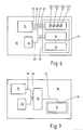
- FIG. 6 shows a schematic illustration of the charger 10 in a form slightly modified compared to FIGS. 1 and 2.
- Control electronics 11 and a reference voltage source 34 are permanently installed in the charger.
- the latter supplies processor 18 with a constant, highly accurate and digitized voltage value.
- the electrical quantities stored in the program memory 17 can thereby be based on the reference voltage be related.
- a corresponding reference voltage source can be contained in the control electronics 11.
- the program memory 17 and the processor 18 are part of the program module 13.
- the potentiometers 19 .22 with adjusting screws 24. .27 belong to the program module 13.
- the program module 13 can be detached from the battery charger 10 via a plug connection.
- the plug connection itself is not designated in more detail in FIG.
- the lines 39, 40 can each have several contain individual, separate conductors.
- FIG. 7 A further embodiment is shown in FIG. 7.
- the processor 18 is not arranged in the area of the program module 13, but rather is firmly arranged in the battery charger 10.
- lines 39, 40 are provided between processor 18 and control electronics 11 or processor 18 and reference voltage source 34.
- the program module 13 only consists of the program memory 17.
- the latter is an EPROM with a capacity of 8 kB.
- Programs for carrying out one or more charging methods and also battery setpoints are stored in the program memory 17. By storing the target values in the program memory 17, almost any number of them (only depending on the capacity of the memory) can be stored and taken into account during the loading process.
- the potentiometers 19 .22 provided in FIG. 6 for setting the setpoint are accordingly not present in FIG. 7.
- the program module 13 or the program memory 17 can be detached from the battery charger 10 via a plug connection.
- the connector (not shown explicitly) contains a line 41 between the program memory 17 and the processor 18 with possibly several separate conductors. This embodiment has the advantage that the component to be replaced is particularly small and therefore inexpensive. In addition, the number of conductors to be considered in the context of the plug connection is small.
- the processor 18 together with the program memory 17 is part of the program module 13.
- the lines 39, 40 can then be disconnected within the scope of the plug connection between the program module 13 and the battery charger 10.
- the battery charger 10 can be adapted to any charging method and each battery type by exchanging the plug-in program module 13.
Landscapes
- Engineering & Computer Science (AREA)
- Power Engineering (AREA)
- Charge And Discharge Circuits For Batteries Or The Like (AREA)
- Secondary Cells (AREA)
Applications Claiming Priority (2)
| Application Number | Priority Date | Filing Date | Title |
|---|---|---|---|
| DE3822570A DE3822570A1 (de) | 1988-07-04 | 1988-07-04 | Verfahren zur anpassung eines batterieladegeraetes an unterschiedliche ladeverfahren und batterietypen und batterieladegeraet |
| DE3822570 | 1988-07-04 |
Publications (2)
| Publication Number | Publication Date |
|---|---|
| EP0349995A2 true EP0349995A2 (fr) | 1990-01-10 |
| EP0349995A3 EP0349995A3 (fr) | 1991-01-16 |
Family
ID=6357907
Family Applications (1)
| Application Number | Title | Priority Date | Filing Date |
|---|---|---|---|
| EP19890112225 Withdrawn EP0349995A3 (fr) | 1988-07-04 | 1989-07-04 | Procédé d'adaptation d'un chargeur de batterie à différents procédés de charge et types de batterie et chargeur |
Country Status (2)
| Country | Link |
|---|---|
| EP (1) | EP0349995A3 (fr) |
| DE (1) | DE3822570A1 (fr) |
Cited By (7)
| Publication number | Priority date | Publication date | Assignee | Title |
|---|---|---|---|---|
| EP0470065A1 (fr) * | 1990-07-23 | 1992-02-05 | Industrieelektronik Pölz | Appareil de charge d'accumulateurs |
| EP0450783A3 (en) * | 1990-04-05 | 1992-05-20 | Technophone Limited | Battery charging apparatus |
| EP0458232A3 (en) * | 1990-05-25 | 1992-05-20 | Abb Ceag Licht- Und Stromversorgungstechnik Gmbh | Control- and measurement device for mobile battery powered equipment |
| EP0539775A3 (en) * | 1991-10-30 | 1993-06-09 | Robert Bosch Gmbh | Device for charging a battery |
| EP0523381A3 (en) * | 1991-07-18 | 1993-07-14 | Theo Benning Elektrotechnik Und Elektronik Gmbh & Co. Kg | Device for charging a rechargeable battery |
| EP0448235B1 (fr) * | 1990-02-27 | 1995-08-23 | Sony Corporation | Chargeur de batterie |
| WO2001086777A3 (fr) * | 2000-05-05 | 2002-02-07 | S P E Elettronica Ind Di Polet | Appareil universel et procede de chargement de batteries |
Families Citing this family (1)
| Publication number | Priority date | Publication date | Assignee | Title |
|---|---|---|---|---|
| JPH06124731A (ja) * | 1992-08-31 | 1994-05-06 | Toshiba Corp | 外部バッテリ接続用アタッチメント、バッテリパック及びバッテリ識別制御方法 |
Family Cites Families (4)
| Publication number | Priority date | Publication date | Assignee | Title |
|---|---|---|---|---|
| US4392101A (en) * | 1978-05-31 | 1983-07-05 | Black & Decker Inc. | Method of charging batteries and apparatus therefor |
| DE3528659A1 (de) * | 1985-08-09 | 1987-02-19 | Jungheinrich Kg | Batterieladeanlage |
| US4684872A (en) * | 1985-11-06 | 1987-08-04 | General Battery Corporation | Battery formation charging apparatus |
| DE3637669A1 (de) * | 1986-11-05 | 1988-05-19 | Bosch Gmbh Robert | Vorrichtung zum automatischen feststellen der elektrischen kennwerte eines akkumulators |
-
1988
- 1988-07-04 DE DE3822570A patent/DE3822570A1/de not_active Withdrawn
-
1989
- 1989-07-04 EP EP19890112225 patent/EP0349995A3/fr not_active Withdrawn
Cited By (7)
| Publication number | Priority date | Publication date | Assignee | Title |
|---|---|---|---|---|
| EP0448235B1 (fr) * | 1990-02-27 | 1995-08-23 | Sony Corporation | Chargeur de batterie |
| EP0450783A3 (en) * | 1990-04-05 | 1992-05-20 | Technophone Limited | Battery charging apparatus |
| EP0458232A3 (en) * | 1990-05-25 | 1992-05-20 | Abb Ceag Licht- Und Stromversorgungstechnik Gmbh | Control- and measurement device for mobile battery powered equipment |
| EP0470065A1 (fr) * | 1990-07-23 | 1992-02-05 | Industrieelektronik Pölz | Appareil de charge d'accumulateurs |
| EP0523381A3 (en) * | 1991-07-18 | 1993-07-14 | Theo Benning Elektrotechnik Und Elektronik Gmbh & Co. Kg | Device for charging a rechargeable battery |
| EP0539775A3 (en) * | 1991-10-30 | 1993-06-09 | Robert Bosch Gmbh | Device for charging a battery |
| WO2001086777A3 (fr) * | 2000-05-05 | 2002-02-07 | S P E Elettronica Ind Di Polet | Appareil universel et procede de chargement de batteries |
Also Published As
| Publication number | Publication date |
|---|---|
| DE3822570A1 (de) | 1990-01-11 |
| EP0349995A3 (fr) | 1991-01-16 |
Similar Documents
| Publication | Publication Date | Title |
|---|---|---|
| DE69233127T2 (de) | Verfahren zum Laden einer Wiederaufladbaren Batterie | |
| DE69321490T2 (de) | Wiederaufladbare Batterie und Batterieladesystem | |
| DE19504437B4 (de) | Batterieladegerät | |
| DE4319861B4 (de) | Batterieladegerät und Verfahren zum Aufladen einer Batterie | |
| DE69836403T2 (de) | Verfahren zur Laderegelung und Lader für wiederaufladbare Batterie | |
| DE3220152A1 (de) | Batterieladegeraet | |
| DE2521462A1 (de) | Einrichtung zum abschalten nicht betriebsbedingter verbraucher in einem stromkreis | |
| DE4302201A1 (de) | Batterieladegerät und Verfahren zum Aufladen von Akkumulatoren | |
| EP0349995A2 (fr) | Procédé d'adaptation d'un chargeur de batterie à différents procédés de charge et types de batterie et chargeur | |
| WO2019072488A1 (fr) | Dispositif de stockage d'énergie et système et procédé pour déterminer une capacité d'un dispositif de stockage d'énergie | |
| DE2009911C3 (de) | Ladegerät für Bleibatterien | |
| EP0114871B1 (fr) | Procede et dispositif pour le controle de la capacite a chaque fois chargee d'accumulateurs | |
| DE2831588A1 (de) | Zentrale speisevorrichtung, insbesondere fuer gewerbliche und reisefahrzeuge, z.b. fuer lieferfahrzeuge, motorcaravans, campingwagen und boote | |
| WO2023143881A1 (fr) | Procédé et dispositif de charge d'une batterie à cellules multiples | |
| EP2180540B1 (fr) | Accumulateur doté de plusieurs cellules galvaniques | |
| DE29621472U1 (de) | Batteriesimulator | |
| EP4214816B1 (fr) | Procédé et système d'analyse d'un accumulateur d'énergie, ainsi que système d'approvisionnement énergétique | |
| EP0470065B1 (fr) | Appareil de charge d'accumulateurs | |
| DE2348332B2 (de) | Schaltungsanordnung zum laden eines elektrischen sammlers | |
| EP0419867B1 (fr) | Procédé de régulation de tension | |
| DE3832841C2 (de) | Verfahren zum Laden von wiederaufladbaren Batterien | |
| DE102009050273B4 (de) | Verfahren zum Bestimmen der Kapazität einer Batterie | |
| DE19723968B4 (de) | Verfahren zur Aufladung und Aufladegerät zum Aufladen einer Ni-MH-oder Ni-Cd-Batterie eines Funktelefons | |
| DE102020212769A1 (de) | Verfahren zum unterbrechungsfreien Betreiben eines netzunabhängig betriebenen mobilen Systems und mobiles System | |
| DE567769C (de) | Einrichtung zum selbsttaetigen Laden elektrischer Akkumulatorenbatterien |
Legal Events
| Date | Code | Title | Description |
|---|---|---|---|
| PUAI | Public reference made under article 153(3) epc to a published international application that has entered the european phase |
Free format text: ORIGINAL CODE: 0009012 |
|
| AK | Designated contracting states |
Kind code of ref document: A2 Designated state(s): DE FR GB IT SE |
|
| PUAL | Search report despatched |
Free format text: ORIGINAL CODE: 0009013 |
|
| AK | Designated contracting states |
Kind code of ref document: A3 Designated state(s): DE FR GB IT SE |
|
| 17P | Request for examination filed |
Effective date: 19901231 |
|
| STAA | Information on the status of an ep patent application or granted ep patent |
Free format text: STATUS: THE APPLICATION IS DEEMED TO BE WITHDRAWN |
|
| 18D | Application deemed to be withdrawn |
Effective date: 19930202 |