EP0349986A2 - Corte-pied - Google Patents
Corte-pied Download PDFInfo
- Publication number
- EP0349986A2 EP0349986A2 EP89112213A EP89112213A EP0349986A2 EP 0349986 A2 EP0349986 A2 EP 0349986A2 EP 89112213 A EP89112213 A EP 89112213A EP 89112213 A EP89112213 A EP 89112213A EP 0349986 A2 EP0349986 A2 EP 0349986A2
- Authority
- EP
- European Patent Office
- Prior art keywords
- pedal
- coupling part
- fork legs
- axis
- rotation
- Prior art date
- Legal status (The legal status is an assumption and is not a legal conclusion. Google has not performed a legal analysis and makes no representation as to the accuracy of the status listed.)
- Withdrawn
Links
- 230000008878 coupling Effects 0.000 claims abstract description 129
- 238000010168 coupling process Methods 0.000 claims abstract description 129
- 238000005859 coupling reaction Methods 0.000 claims abstract description 129
- 230000027455 binding Effects 0.000 claims abstract description 40
- 238000009739 binding Methods 0.000 claims abstract description 40
- 230000000295 complement effect Effects 0.000 claims description 11
- 238000003780 insertion Methods 0.000 claims description 6
- 230000037431 insertion Effects 0.000 claims description 6
- 230000005540 biological transmission Effects 0.000 description 3
- 239000000463 material Substances 0.000 description 2
- 238000000034 method Methods 0.000 description 2
- 229920002430 Fibre-reinforced plastic Polymers 0.000 description 1
- 238000004026 adhesive bonding Methods 0.000 description 1
- 230000006835 compression Effects 0.000 description 1
- 238000007906 compression Methods 0.000 description 1
- 238000010276 construction Methods 0.000 description 1
- 238000011109 contamination Methods 0.000 description 1
- 230000001351 cycling effect Effects 0.000 description 1
- 230000000994 depressogenic effect Effects 0.000 description 1
- 230000000694 effects Effects 0.000 description 1
- 239000011151 fibre-reinforced plastic Substances 0.000 description 1
- 239000000725 suspension Substances 0.000 description 1
Images

Classifications
-
- B—PERFORMING OPERATIONS; TRANSPORTING
- B62—LAND VEHICLES FOR TRAVELLING OTHERWISE THAN ON RAILS
- B62M—RIDER PROPULSION OF WHEELED VEHICLES OR SLEDGES; POWERED PROPULSION OF SLEDGES OR SINGLE-TRACK CYCLES; TRANSMISSIONS SPECIALLY ADAPTED FOR SUCH VEHICLES
- B62M3/00—Construction of cranks operated by hand or foot
- B62M3/08—Pedals
- B62M3/086—Attachments between shoe and pedal other than toe clips, e.g. cleats
-
- Y—GENERAL TAGGING OF NEW TECHNOLOGICAL DEVELOPMENTS; GENERAL TAGGING OF CROSS-SECTIONAL TECHNOLOGIES SPANNING OVER SEVERAL SECTIONS OF THE IPC; TECHNICAL SUBJECTS COVERED BY FORMER USPC CROSS-REFERENCE ART COLLECTIONS [XRACs] AND DIGESTS
- Y10—TECHNICAL SUBJECTS COVERED BY FORMER USPC
- Y10T—TECHNICAL SUBJECTS COVERED BY FORMER US CLASSIFICATION
- Y10T74/00—Machine element or mechanism
- Y10T74/21—Elements
- Y10T74/2164—Cranks and pedals
- Y10T74/2168—Pedals
- Y10T74/217—Pedals with toe or shoe clips
Definitions
- the invention relates to a pedal binding for releasably coupling a shoe to a pedal of a bicycle rotatable about a pedal axis.
- the driver's shoe For higher performance in sports and racing cycling, the driver's shoe must be held firmly on the pedal via a pedal binding, so that not only compressive forces can be transmitted to the pedal, but also tensile forces.
- Conventional pedal bindings that can be subjected to pressure and tension have a bracket that is firmly connected to the pedal, which the driver grips under with his toe from behind and a strap that runs approximately over the instep. The strap spans the shoe comparatively tight, with the result that the foot cannot be released quickly enough from the binding in the event of a fall and the driver is often seriously injured in the fall.
- the pedal forming a tread surface is provided with a locking part which extends in the direction of the pedal axis of rotation and which engages carries its resilient locking pins in the direction of the axis of rotation of the pedal.
- a complementary recess is provided in the shoe sole or in a coupling part connected to the shoe, into which the locking part engages when the shoe is placed on the pedal.
- locking openings are provided, into which the locking pins engage when the shoe is placed on the pedal and lock the shoe on the pedal.
- the recess widens towards the tip of the shoe in order to facilitate the insertion of the latch part into the recess.
- the locking pins of the pedal-side locking part are guided in bores in the locking part and are prestressed to the outside by helical compression springs.
- Such a construction is comparatively complex and prone to failure, since the sliding guides of the locking pins can get stuck in the bores, for example due to soiling. Loosening or jamming the locking pins changes the triggering properties of the pedal binding, which is undesirable.
- pedal binding consisting of two coupling parts is known from European patent 146 454.
- hooks are attached to the pedal-side coupling part in the direction of travel in front of and behind the pedal axis of rotation, which overlap the assigned tabs of the shoe-side coupling part.
- the rear hook in the direction of travel is biased towards the shoe-side coupling part by a spring.
- Such a pedal binding allows the transmission of tensile forces and releases the shoe when it rotates around the shin axis, but it does not released if the foot is tilted around its longitudinal axis.
- the pedal binding according to the invention is based on the type known from European patent application 155 114 and, in accordance with this pedal binding, comprises a pedal-side coupling part which forms a step surface and a shoe-side coupling part which can be placed on the step surface.
- a first of the two coupling parts has a recess which is open transversely to the tread surface and which is provided with latching elements on two side surfaces opposite one another in the direction of the pedal axis of rotation.
- a second of the two coupling parts comprises a locking part which can be inserted into the recess and which carries complementary locking elements which can be locked elastically on the locking elements of the first coupling part.
- both coupling parts have a fork-like shape transverse to the pedal axis freely projecting fork legs, of which the fork legs of a first coupling part delimit a recess between them, into which the fork legs of the second coupling part protrude in the opposite direction.
- a recess which is open in the pedaling direction is also present on the pedal, so that the risk of contamination of the interlocking locking elements is reduced. This applies in particular when the fork legs of the shoe-side coupling part engage between the fork legs of the pedal-side coupling part.
- the initial forces required to release the latching connection are determined not only by the spring properties of the elastic fork legs, but also by the shape of the mutually complementary latching members.
- spherical cap-shaped locking members of the one coupling part are assigned conical recesses of the other coupling part.
- the locking connection must meet several requirements. On the one hand, it must be able to transmit sufficiently high tensile forces, but on the other hand it must be so smooth that it can be released by a more or less arbitrary rotational movement of the foot in the event of danger.
- mutually adjacent inclined thrust surfaces are formed on the two coupling parts in the case of latching elements which are locked together and which release the locking of the latching elements when the two coupling parts rotate relative to a transverse axis of rotation relative to the pedal axis of rotation.
- the latching members are arranged behind the pedal axis of rotation in the direction of travel, while in the direction of travel in front of the pedal axis on the pedal-side coupling part there is a hook which is open against the direction of travel and which overlaps a tab of the shoe-side coupling part which projects to the hook.
- the aforementioned oblique thrust surfaces are expediently formed on the hook and the tab and move the coupling parts relative to one another in the direction of travel during the relative rotation. The sloping surfaces of the hook and the tab also make it easier to loosen the hook-tab connection in the event of danger.
- the hook viewed in the direction of the tread surface, has an angular shape, the angular legs of which extend essentially tangentially to the rotating circles of the bracket, about pivot axes defined by the latching elements.
- the angular shape of the hook makes it easier to close the latching connection, since it centers the tab of the shoe-side coupling part in the center of the pedal-side coupling part.
- the insertion of the tab under the hook is considerably facilitated if the coupling part on the pedal side has an opening in the area of the hook suitable for receiving the tab.
- the opening expediently has a wedge shape towards the hook and forcibly guides the tab into it under the hook.
- the recess of the first coupling part which receives the latching element of the second coupling part expediently has insertion bevel surfaces which widen the recess substantially along its entire boundary towards the second coupling part.
- the insertion bevels facilitate centering of the coupling parts relative to one another when the latching connection is closed.
- both coupling parts are provided with fork legs directed towards each other, the ends of the fork legs can also be provided with mutually complementary inclined surfaces which run obliquely from bottom to top in the direction of travel and prevent the fork legs from accidentally getting caught.
- the fork legs which bring about the suspension of the latching members, can be integrally formed on the coupling part. In a preferred embodiment, however, they are integrally formed on a web section of an essentially U-shaped locking element, which is held in the region of the web section on a base part of the coupling part.
- the base part and the coupling part can thus consist of different materials, fiber-reinforced plastic materials, in particular for the latching element, having proven to be particularly suitable and, moreover, the latching element can also be exchanged, for example in order to change its spring hardness.
- the spring force of the locking element determines the tensile strength of the pedal binding and is expediently adjustable in order to be able to adapt it to the respective usage situation.
- the spring force can be changed in a simple manner without having to remove the locking element from the base part if the web portion of the locking element is mounted in the region of the ends of the fork legs adjacent to it by means of two joints on the base part and between the two joints in the direction of Fork leg adjustable stop is provided, via which the web portion is supported on the base part.
- the stop can be, for example, an adjusting screw screwed into the web section or the base part.
- a step-by-step, simple adjustment allows a step eccentric disk mounted on the base part to serve as a stop.
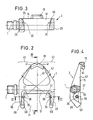
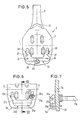
- the pedal binding of a bicycle shown in FIG. 1 in combination and in FIGS. 2 to 5 in its components comprises a pedal-side first coupling part 3 which can be rotated about a pedal axis of rotation 1 and on which a shoe-side second coupling part 5 is explained in more detail below is releasably locked.
- the coupling part 5 carries on a base plate 7 a conventional foot hook 9 which surrounds the toe and, together with a strap 11 and a web 13 running parallel to the pedal axis of rotation 1, fixes the shoe in a conventional manner relative to the base part 7.
- the pedal-side coupling part 3 forms on its upper side a tread 15 on which the base part 7 rests for the transmission of pressure forces.
- the pedal-side coupling part 3 is provided with a hook 19 which is open against the direction of travel and which engages over a tab 21 formed on the front end of the base part 7.
- an essentially U-shaped locking element 23 is attached to the base part 7 of the shoe-side coupling part 5, which consists of a web section 25 extending in the direction of the pedal axis of rotation and two of the end regions of the web section 25 in the direction of travel freely protruding fork legs 27 there.
- the fork legs 27 of the locking element 23 engage between two fork legs 29 which protrude freely from the pedal-side coupling part 3 against the direction of travel and which form a recess 31 between them for receiving the locking element 23.
- the fork legs 27 of the locking element 23 can be elastically deflected in the direction of the axis of rotation of the pedal 1 and, in the region of their ends, have spherical-cap-shaped locking members 33 in the region of the ends facing the fork legs 29, which engage in complementary locking members 35 in the form of conical recesses in the mutually facing side surfaces of the fork legs 29 intervene.
- the spring force of the fork legs 27 is dimensioned so large that the tensile forces occurring in bicycle operation can be transmitted via the latching members 33, 35 and the hook-tab connection 19, 21. If the tensile forces exceed the holding force of the latching connection 33, 35, the shoe-side coupling part 5 is released from the pedal-side coupling part 3.
- the latching connection between the shoe-side clutch part 5 and the pedal-side clutch part 3 can be released not only by excessive tensile forces, but also by almost any rotational or tilting movement of the shoe and thus the shoe-side clutch part 5 relative to the pedal-side clutch part 3.
- the coupling part 5 rotates about a vertical axis running transversely to the tread surface 15, for example the axis 37, normally only one of the two locking connections 33, 35 is released and the shoe-side coupling part 5 pivots about a pivot axis 39 determined by the center of the cap of the locking element 33 (FIG . 2).
- the hook 19 and the tab 21 have mutually complementary inclined pushing surfaces 45, 47 which run obliquely from top to bottom in the direction of travel 17.
- the angled pushing surfaces 45, 47 extend at the same angle to the tread surface 15 and rest against one another when the latching connection is closed.
- the oblique push surfaces 45, 47 support the release movement of the latching connection 33, 35 by moving the coupling part 5 against the direction of travel relative to the coupling part 3 slide.
- the oblique push surfaces 45, 47 force an opening movement of the latching connection.
- Another pair of inclined thrust surfaces which supports the opening movement, is formed by an inclined thrust surface 51, which runs obliquely upwards from below in the direction of travel 17, between the two fork legs 29 of the coupling part 3, on the one hand, and the free ends of the fork legs 27 designed as inclined surfaces 53.
- the fork legs 27 are closely adjacent or abut against the inclined push surface 51 when the latching connection 33, 35 is closed, so that when the pivoting movement of the coupling part 5 about the axes of rotation 39, the release movement of the latching connection by lifting the fork leg 27 out of the recess at least in one direction of rotation 31 support.
- the inclined surfaces 51, 53 support the release movement and counteract the hooking of the coupling parts 3, 5.
- the inclined push surfaces 45, 47 and 51, 53 ensure a defined triggering behavior of the pedal Binding during tilting and pivoting movements of the coupling parts 3, 5 around essentially any spatial axes.
- inclined surfaces 55 are also formed on the mutually facing sides of the fork legs 29, which together with the oblique thrust surface 51 expand upwards in a funnel shape towards the tread surface 15 and the insertion of the latching members 33 into the recesses or latching members 35 facilitate.
- a triangularly tapering opening 57 toward the hook 19 is provided, into which the base part 7 dips with the tab 21 in front when the pedal binding is closed, until the tab 21 is pushed through Combined pushing and tilting movement of the coupling part 5 bears under the hook 19.
- the angular shape of the hook 19 ensures that the tab 21 is centered and the inclined surfaces 51, 55 ensure that the latching members 33 are centered relative to the latching members 35 when the region of the coupling part 5 lying behind in the direction of travel is subsequently depressed.
- inclined surfaces 59 which extend at substantially the same angle to the tread 15 as the inclined surfaces 53 of the fork legs 27 and extend obliquely upward in the direction of travel 17.
- the inclined surfaces 53, 59 prevent the coupling part 5 from getting caught on the coupling part 3 when it is placed on it.
- the web is Cut 25 of the locking element 23 in the region of the ends of the web legs 27 facing it via two joints 61 connected to the base part 7.
- a step eccentric disk 63 is rotatably mounted on the base part 7 about an axis of rotation 65.
- the step eccentric disk 63 forms a stop which can be adjusted in steps for the web section 25 which is flexible between the joints 61.
- the stop height By changing the stop height, the distance between the locking members 33 in the direction of the axis of rotation 1 and thus the locking force generated when the locking connection is closed are changed.
- other adjustable stops for example in the form of set screws or the like, can be provided.
- the adjustable part of the stop can also be provided on the web section 25 and supported on a fixed counter-stop of the base part 7.
- the attachment can be non-detachable, for example by gluing, or detachable, for example by means of screws indicated at 67, in order to be able to replace the latching element if necessary.
- the latching force is set by adjusting the latching members 33a in the direction of the pedal axis of rotation 1a.
- the locking members 33a are provided with a threaded shaft 69, which holds them adjustable in the fork legs 27a.
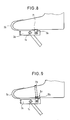
- FIG. 8 shows a variant in which a shackle 9b encompassing the tip of the shoe is attached directly to the pedal-side coupling part 3b which can be rotated about the axis of rotation of the pedal 1b.
- the shoe-side coupling part 5b which comprises at least one latching element, similar to the latching element 23 or 23a, is fastened directly to the shoe by connecting elements 71, for example screwed, riveted, glued or welded on.
- Figure 9b shows a variant in which a bracket 9c is in turn directly attached to the pedal-side coupling part 3c rotatable about the pedal axis 1c, while the shoe-side coupling part 5c, similar to Figure 1, comprises a belt 11c and a latching web 13c.
- the shoe-side coupling part 5c comprises at least the elements 7 and 23 or 7a and 23a of the exemplary embodiments in FIGS. 1 to 7.
- the shoe-side coupling part 5c is held on the shoe exclusively by the belt 11c.
- the coupling part 3c on the pedal side like the coupling part 3b, can also be used without the coupling part 5c or 5b on the shoe side.
Landscapes
- Engineering & Computer Science (AREA)
- Chemical & Material Sciences (AREA)
- Combustion & Propulsion (AREA)
- Transportation (AREA)
- Mechanical Engineering (AREA)
- Mechanical Control Devices (AREA)
- Steering Devices For Bicycles And Motorcycles (AREA)
Applications Claiming Priority (2)
| Application Number | Priority Date | Filing Date | Title |
|---|---|---|---|
| DE3822663 | 1988-07-05 | ||
| DE3822663A DE3822663A1 (de) | 1988-07-05 | 1988-07-05 | Pedal-bindung |
Publications (2)
| Publication Number | Publication Date |
|---|---|
| EP0349986A2 true EP0349986A2 (fr) | 1990-01-10 |
| EP0349986A3 EP0349986A3 (fr) | 1990-07-04 |
Family
ID=6357959
Family Applications (1)
| Application Number | Title | Priority Date | Filing Date |
|---|---|---|---|
| EP89112213A Withdrawn EP0349986A3 (fr) | 1988-07-05 | 1989-07-04 | Corte-pied |
Country Status (3)
| Country | Link |
|---|---|
| US (1) | US4969375A (fr) |
| EP (1) | EP0349986A3 (fr) |
| DE (1) | DE3822663A1 (fr) |
Cited By (1)
| Publication number | Priority date | Publication date | Assignee | Title |
|---|---|---|---|---|
| EP0516013B1 (fr) * | 1991-05-30 | 1997-01-08 | Shimano Inc. | Dispositif pour une pédale de bicyclette avec surface de la pédale variable |
Families Citing this family (9)
| Publication number | Priority date | Publication date | Assignee | Title |
|---|---|---|---|---|
| US5142938A (en) * | 1989-08-25 | 1992-09-01 | Sampson Sports, Inc. | Bicycle cleat and pedal with adjustable floating relationship |
| DE69018196T2 (de) * | 1989-11-14 | 1995-09-14 | Shimano Kk | Verbindungsstruktur zwischen Fahrradpedal und Stossplatte, Fahrradpedal und Stossplatte. |
| US5737977A (en) * | 1996-05-09 | 1998-04-14 | Surdi; Richard J. | Selectively releasable toe clip |
| DE69817585T2 (de) | 1997-04-18 | 2004-06-24 | The Burton Corp. | Aktives kupplungsystem zur kupplung eines snowboardstiefels an einer bindung |
| US6694846B2 (en) * | 2002-02-28 | 2004-02-24 | Shimano Inc. | Bicycle pedal |
| USD586986S1 (en) * | 2007-10-18 | 2009-02-24 | Wolverine World Wide, Inc. | Footwear sole |
| US8312791B2 (en) * | 2009-10-14 | 2012-11-20 | Shimano Inc. | Bicycle pedal |
| EP2547577B1 (fr) * | 2010-03-15 | 2015-12-16 | Evolution Racing Products, LLC | Systeme de retenue active par interface de commande pour attacher des chaussures de motocycliste a un repose-pieds |
| US8794106B2 (en) | 2011-08-31 | 2014-08-05 | Evolution Racing Products, Llc | Mechanical restraint for securing motorcycle rider footwear to footpeg |
Family Cites Families (11)
| Publication number | Priority date | Publication date | Assignee | Title |
|---|---|---|---|---|
| GB190916829A (en) * | 1909-07-19 | 1910-04-21 | Zoe Zook Woolery | Improvements in Toy Parachutes. |
| CH205395A (de) * | 1938-12-02 | 1939-06-15 | Meier Fritz | Einrichtung an Fahrradpedalen zum Schutze der Füsse des Fahrers gegen Kälte. |
| FR875354A (fr) * | 1941-09-18 | 1942-09-18 | Dispositif destiné à faciliter le pédalage des cycles | |
| GB703040A (en) * | 1952-03-21 | 1954-01-27 | Verny Mora Steinvorth | Improvements in or relating to devices for attaching cyclist's shoes to the pedals of a cycle |
| ES403352A1 (es) * | 1971-06-19 | 1975-04-16 | Uccellini | Dispositivo para fijar una zapatilla de ciclista al pedal de una bicicleta. |
| DE3149345A1 (de) * | 1981-12-12 | 1983-06-16 | Hubert 5100 Aachen Küpper | Bindung an fahrradpedalen |
| FR2526748B1 (fr) * | 1982-05-12 | 1987-05-29 | Christol Lilian | Dispositif de pedalage pour cycle et chaussure adaptee |
| US4538480A (en) * | 1983-07-01 | 1985-09-03 | Trindle James J | Bicycle pedal and shoe |
| FR2556687B1 (fr) * | 1983-12-16 | 1986-04-18 | Look Sa | Dispositif de fixation d'une chaussure sur une pedale de bicyclette |
| WO1985004029A1 (fr) * | 1984-02-27 | 1985-09-12 | Howell Richard J | Appareil a pedaler pour bicyclette |
| DE3561870D1 (en) * | 1984-05-18 | 1988-04-21 | Beyl Jean Joseph Alfred | Fastening device for a shoe to a pedal, shoe and pedal provided with this device |
-
1988
- 1988-07-05 DE DE3822663A patent/DE3822663A1/de not_active Withdrawn
-
1989
- 1989-07-04 EP EP89112213A patent/EP0349986A3/fr not_active Withdrawn
- 1989-07-05 US US07/375,817 patent/US4969375A/en not_active Expired - Fee Related
Cited By (1)
| Publication number | Priority date | Publication date | Assignee | Title |
|---|---|---|---|---|
| EP0516013B1 (fr) * | 1991-05-30 | 1997-01-08 | Shimano Inc. | Dispositif pour une pédale de bicyclette avec surface de la pédale variable |
Also Published As
| Publication number | Publication date |
|---|---|
| EP0349986A3 (fr) | 1990-07-04 |
| DE3822663A1 (de) | 1990-01-11 |
| US4969375A (en) | 1990-11-13 |
Similar Documents
| Publication | Publication Date | Title |
|---|---|---|
| DE69216472T2 (de) | Vorrichtung für Fahrradpedale mit variabler Tretfläche | |
| DE69008810T2 (de) | Schuhbefestigungsvorrichtung an einem Fahrradpedal oder dergleichen, Fahrradpedal, Riegel und Schuhsohle für eine derartige Vorrichtung. | |
| DE2942806C2 (de) | Skibindung, insbesondere Langlaufskibindung | |
| DE69607454T2 (de) | Skischuhbindungssystem für Snowboards | |
| DE202009019128U1 (de) | Zeheneinheit für Tourenskibindung | |
| DE2610041B2 (fr) | ||
| DE3426103A1 (de) | Sicherheitsbindung zwischen schuh und pedal einer tretkurbel eines fahrrades o.dgl. | |
| EP0934762B1 (fr) | Fixation pour planche de glisse, notamment snowboard | |
| DE3924915A1 (de) | Langlaufskibindung der scharnierbauart | |
| DE3128169C2 (de) | Abnehmbarer Tragegriff | |
| DE3619043A1 (de) | Alpiner skistiefel | |
| DE3102010A1 (de) | "sicherheitsskibindung" | |
| EP0349986A2 (fr) | Corte-pied | |
| CH650687A5 (de) | Skibindung mit einem trittgestell. | |
| EP3639900B1 (fr) | Mâchoire avant et pièce de maintient amovible pour une fixation de randonnée à ski | |
| DE3447012C2 (de) | Vorrichtung aus einer auf einem Ski befestigten Sicherheitsskibindung und einem Skistiefel sowie Skistiefel und Skibindung | |
| DE3342158A1 (de) | Bindung fuer einen skischuh | |
| EP3878528B1 (fr) | Unité avant pour une fixation de ski doté d'une aide au chaussage | |
| DE2519495B2 (de) | Skibindung | |
| EP0271693B1 (fr) | Mâchoire avant pour fixations de sécurité de ski | |
| DE2509614C2 (de) | Sicherheitsanordnung zum selbständigen Ausrichten eines Skistiefels gegenüber dem Ski und zum Halten des Skistiefels in der ausgerichteten Stellung | |
| EP0928267A1 (fr) | Pedale de bicyclette | |
| EP0466860B1 (fr) | Elements de fixation de ski, en particulier machoires avant | |
| DE3005978C2 (fr) | ||
| DE102022130901A1 (de) | Vordereinheit mit absenkbarer Halteeinrichtung |
Legal Events
| Date | Code | Title | Description |
|---|---|---|---|
| PUAI | Public reference made under article 153(3) epc to a published international application that has entered the european phase |
Free format text: ORIGINAL CODE: 0009012 |
|
| AK | Designated contracting states |
Kind code of ref document: A2 Designated state(s): DE FR GB IT SE |
|
| PUAL | Search report despatched |
Free format text: ORIGINAL CODE: 0009013 |
|
| AK | Designated contracting states |
Kind code of ref document: A3 Designated state(s): DE FR GB IT SE |
|
| 17P | Request for examination filed |
Effective date: 19900911 |
|
| 17Q | First examination report despatched |
Effective date: 19920117 |
|
| STAA | Information on the status of an ep patent application or granted ep patent |
Free format text: STATUS: THE APPLICATION IS DEEMED TO BE WITHDRAWN |
|
| 18D | Application deemed to be withdrawn |
Effective date: 19920804 |