EP0347834B1 - Burner head for a forced-draft gas burner - Google Patents
Burner head for a forced-draft gas burner Download PDFInfo
- Publication number
- EP0347834B1 EP0347834B1 EP89111185A EP89111185A EP0347834B1 EP 0347834 B1 EP0347834 B1 EP 0347834B1 EP 89111185 A EP89111185 A EP 89111185A EP 89111185 A EP89111185 A EP 89111185A EP 0347834 B1 EP0347834 B1 EP 0347834B1
- Authority
- EP
- European Patent Office
- Prior art keywords
- cross
- burner
- combustion
- burner head
- lines
- Prior art date
- Legal status (The legal status is an assumption and is not a legal conclusion. Google has not performed a legal analysis and makes no representation as to the accuracy of the status listed.)
- Expired - Lifetime
Links
Images

Classifications
-
- F—MECHANICAL ENGINEERING; LIGHTING; HEATING; WEAPONS; BLASTING
- F23—COMBUSTION APPARATUS; COMBUSTION PROCESSES
- F23D—BURNERS
- F23D14/00—Burners for combustion of a gas, e.g. of a gas stored under pressure as a liquid
- F23D14/34—Burners specially adapted for use with means for pressurising the gaseous fuel or the combustion air
-
- F—MECHANICAL ENGINEERING; LIGHTING; HEATING; WEAPONS; BLASTING
- F23—COMBUSTION APPARATUS; COMBUSTION PROCESSES
- F23C—METHODS OR APPARATUS FOR COMBUSTION USING FLUID FUEL OR SOLID FUEL SUSPENDED IN A CARRIER GAS OR AIR
- F23C9/00—Combustion apparatus characterised by arrangements for returning combustion products or flue gases to the combustion chamber
- F23C9/006—Combustion apparatus characterised by arrangements for returning combustion products or flue gases to the combustion chamber the recirculation taking place in the combustion chamber
-
- F—MECHANICAL ENGINEERING; LIGHTING; HEATING; WEAPONS; BLASTING
- F23—COMBUSTION APPARATUS; COMBUSTION PROCESSES
- F23D—BURNERS
- F23D14/00—Burners for combustion of a gas, e.g. of a gas stored under pressure as a liquid
- F23D14/34—Burners specially adapted for use with means for pressurising the gaseous fuel or the combustion air
- F23D14/36—Burners specially adapted for use with means for pressurising the gaseous fuel or the combustion air in which the compressor and burner form a single unit
-
- F—MECHANICAL ENGINEERING; LIGHTING; HEATING; WEAPONS; BLASTING
- F23—COMBUSTION APPARATUS; COMBUSTION PROCESSES
- F23D—BURNERS
- F23D2900/00—Special features of, or arrangements for burners using fluid fuels or solid fuels suspended in a carrier gas
- F23D2900/11403—Flame surrounding tubes in front of burner nozzle
Definitions
- the invention relates to a burner head for a forced gas burner according to the preamble of the main claim.
- a known fan gas burner of this type (FR-PS 1 507 416)
- the problem underlying such gas burners can be seen. Since the gas is supplied to the combustion chamber at a relatively low pressure, in order to achieve homogeneous mixing with the combustion air, the gas supply must be fanned out and mixed with the supplied combustion air in a suitable manner as homogeneously as possible. In addition, there is a risk with such blower gas burners that the flame breaks off, which is then automatically re-ignited, which can lead to an unpleasant pulsation.
- this known fan gas burner is inside a baffle ring is arranged by the combustion tube, through which the flame is to be stabilized.
- the oil burner has an oil spray cone generated by the oil burner nozzle of high flow energy, into which the combustion air is blown with likewise high air pressure and under swirl, in order to ensure sufficient combustion for good combustion to achieve the required mixing of oil mist and combustion air.
- the swirl and baffle plates in the flame tube this naturally results in a high fuel gas velocity, which causes recirculation through the radial openings between the fuel tube and flame tube.
- the flame tube on the side facing the combustion tube namely downstream of the recirculation openings, is expanded in order to superimpose a funnel effect on the Venturi effect.
- the invention has for its object to develop a burner head for fan gas burners, with which the NO x components in the exhaust gas finally discharged to one A value that can be reduced is, if possible, less than 50 ppm NO x .
- This object is achieved by the burner head according to the invention with the characterizing features of the main claim.
- This burner head according to the invention has the advantage over the known blower gas burners that in a very simple manner and without increasing the pressure of the fuel gas or the supplied combustion air and using the known effect of exhaust gas recirculation, a substantial reduction in the NO x content is possible, namely up to below 50 ppm.
- the diameters of the combustion tube and the flame tube can advantageously be kept almost the same, although at these low speeds of the gas / air mass flow with effective exhaust gas recirculation, low NO x values, reduced CO values and a high burner output with high flame stability can be achieved.
- the diameter of the flame head is significantly larger than that of the burner tube due to the sudden increase in volume of the gas caused by high heat development, with the consequent installation disadvantages.
- the webs against which the flame flows can be designed in a wide variety of ways.
- the decisive factor is that the heat flow experiences a jam with an overpressure zone upstream and a vacuum zone downstream of the web, the former causing flame stabilization and the latter initiating the recirculation of the exhaust gas.
- the device for the fuel gas distribution in the manner of a cross-flow burner has a burner ring arranged transversely to the burner head axis with a burner plate, with radially arranged fuel gas nozzles and with axially provided through openings for the combustion air.
- These flame zones form the root of the burner flame, which continues for a second combustion stage downstream of the webs in the flame tube.
- the edge region of the burner ring towards the combustion tube has notches formed as slits apart from an annular gap as additional through openings for the combustion air.
- a swirl disk for combustion air is arranged in the combustion tube upstream of the device for the fuel gas distribution.
- this swirl disk which in a known manner has segments which are inclined against one another and which is also known as a swirl disk, causes the combustion air to receive a helical swirl movement.
- the main result of this is that the combustion air is forced to a longer dwell time on its way to the flame root, apart from the fact that a much better mixing between fuel gas and combustion air is brought about.
- this swirling effect of the combustion air continues through the slits down to the webs, and promotes the standing vortices which form in the flame tube due to the webs and which cause the exhaust gas recirculation.
- these are always arranged downstream of the fuel gas nozzles or air passage openings with a correspondingly different effect.
- the webs are arranged on a web ring, which can be designed in a wide variety of ways.
- the webs on the inside can also be connected to each other by a ring, creating a type of perforated disc.
- the actual combustion air blower with motor and fan wheel is not shown, but only part 2 of the gas burner housing which belongs to the burner head, i.e. which is connected directly to the boiler with the combustion chamber.
- the combustion air is supplied to the burner head 1 in the direction of arrow I via the burner housing, which is otherwise not shown.
- the fuel gas is fed radially to the burner head 1 here via a gas line 3 and passed on within it via a tubular distributor device 4.
- the tubular distributor device is closed in the direction of the combustion chamber by a burner ring 5 and a burner plate 6.
- Radial fuel gas nozzles 7 are provided between the burner plate 6 and the burner ring 5 for an exit of the fuel gas provided transversely to the burner head axis.
- the flame roots of a short burner flame begin without additional baffles being required for this.
- One of the air passage openings 9 is designed as an annular gap between the burner ring 5 and a burner tube 10 which is inserted over the burner ring 5 and the tubular distributor device 4 and which is plugged radially sealingly into the housing 2 of the gas burner and fastened thereon.
- a flame tube 13 is fastened to the combustion tube 10 at a distance, which surrounds the first part of the burner flame 14 and, with the exception of the locations at which fastening tabs 15 are arranged, an annular gap 16 between the combustion tube 10 and the flame tube 13 arises, through which exhaust gases can recirculate from the combustion chamber of the boiler back into the flame tube.
- the flame tube 13 could also have a larger diameter than the combustion tube 10.
- the web ring 11 with the webs 12 causes a slight constriction of the flame mass flow flowing past, which results in a slight acceleration of the flow velocity with a slight deflection at the same time radially inwards, so that "standing" vortices form on the webs 12, which lead to the suction of the exhaust gases from the annular gap 16 and thus to exhaust gas recirculation, and which are also supported by the injector effect of the flame mass flow in the flame tube 13.
- the cool combustion air flowing in through the air passage openings 9 on the wall of the combustion tube 10 is also partially guided into the flame center, whereby a reduction in the flame temperatures is achieved with the correspondingly slightly cooled, lower-oxygen, recirculating exhaust gases, with a corresponding reduction in the NO x -Share down to less than 40 ppm.
- a swirl disk 17 is arranged in the burner head 1, which has almost the diameter of the combustion tube 10, and by means of the segments 18 of which are displaced relative to one another, a helical swirl movement of the combustion air is achieved.
- the air passage openings 9 are provided with sections 19 which have a corresponding influence on the speed of the combustion air flow and, in conjunction with the swirl of the air flow caused by the swirl disk 17, an improvement in the torus swirls and the fuel gas / combustion air mixture preparation.
- a free inner diameter d remains between the free ends 22 of the webs 12, which has a specific ratio to the outer diameter D and the ring width b of the outer, non-perforated section 21 of the web ring stands.
- the webs 12 are designed as sheet metal flags of width B, which are evenly distributed with their web foot 20 and in a flat area on the outer ring section 21 of the web ring 11 and merge into section 21 in a rounded manner.
- the length of the webs between the free ends 22 up to the web foot is marked with L.
- the through openings 23 of the web ring 11 between the webs 12 have a drop-shaped cross section which widens radially outward and is open to the inner diameter of the web ring 11.
- the lateral boundaries of the web-shaped webs 12 are formed parallel to the web foot 20, and there are also the base edges 27 of the through openings 23 by which the web feet 20 are connected to one another, straight, so that the cross section of the through openings 23 in this variant has the shape of an open top trapezoid.
- FIGS. 7 and 8 A further variant of the web ring 11 is shown in FIGS. 7 and 8, in which sheet flaps 28 are fastened in a star-shaped manner, for example spot-welded or riveted, on the web ring 28, which is also in one piece and made up of a tubular section 26 and an outer, non-perforated ring section 21.
- the remaining passage cross section of the passage openings 23 thus formed corresponds to that of the variant shown in FIG. 4.
- FIGS. 9 and 10 Another design of the web ring 11 is shown in FIGS. 9 and 10, in which the web ring is designed in each case as a perforated plate, with oval through openings 23 in FIG. 9 and rectangular through openings 23 in FIG. 10.
- the burner head according to the invention works as follows: Combustion air is admixed via the air passage openings 9 and the slots 19 to the fuel gas emerging via the radially inward and outward fuel gas nozzles 7 of the burner ring 5, so that mixtures are present in the flame root, i.e. upstream of the web ring Different gas concentrations are available. While combustion takes place near the air passage openings 9 and 19 with a very large excess of air, the combustion takes place in the vicinity of the fuel gas nozzles 7 with a lack of air. In both cases, the combustion temperature therefore remains low, so that there is a very low NO x emission in each of these partial flames.
- This vacuum zone which is open towards the annular gap 16 in accordance with the design of the web rings 11, causes the exhaust gases surrounding the combustion tube 10 and the flame tube 13 to be drawn in, so that a desired exhaust gas recirculation occurs.
- the exhaust gas is thus conducted into the flame through the interstices formed by the webs 12 and has a lowering of the flame temperature and thereby reducing NO x .
- the CO content in the exhaust gas is reduced, quite apart from the fact that the web ring 11 brings about anchoring of the flame, which is desired in gas-blown burners, that is to say prevents the flame from being torn off.
- This two-stage combustion with exhaust gas recirculation finally has the advantage that a fan gas burner with the burner head according to the invention can be used largely independently of the design of the combustion chamber.
Abstract
Description
Die Erfindung geht aus von einem Brennerkopf für einen Gebläsegasbrenner nach der Gattung des Hauptanspruchs. Bei einem bekannten Gebläsegasbrenner dieser Art (FR-PS 1 507 416) wird die derartigen Gasbrennern zugrundeliegende Problematik ersichtlich. Da das Gas mit relativ niederem Druck der Brennkammer zugeführt wird, muß, um eine homogene Vermischung mit der Verbrennungsluft zu erreichen, die Gaszuführung aufgefächert und in geeigneter Weise mit der zugeführten Verbrennungsluft möglichst homogen vermischt werden. Außerdem besteht bei derartigen Gebläsegasbrennern die Gefahr, daß die Flamme abreißt, die dann automatisch wieder neu gezündet wird, was zu einem unangenehmen Pulsieren führen kann. Bei diesem bekannten Gebläsegasbrenner ist innerhalb des Brennrohres ein Stauring angeordnet, durch den die Flamme stabilisiert werden soll.The invention relates to a burner head for a forced gas burner according to the preamble of the main claim. In a known fan gas burner of this type (FR-PS 1 507 416), the problem underlying such gas burners can be seen. Since the gas is supplied to the combustion chamber at a relatively low pressure, in order to achieve homogeneous mixing with the combustion air, the gas supply must be fanned out and mixed with the supplied combustion air in a suitable manner as homogeneously as possible. In addition, there is a risk with such blower gas burners that the flame breaks off, which is then automatically re-ignited, which can lead to an unpleasant pulsation. In this known fan gas burner is inside a baffle ring is arranged by the combustion tube, through which the flame is to be stabilized.
Die hohen Temperaturen, besonders bei der Verbrennung von Erdgas führt zu einem hohen NOx-Anteil im Abgas, trotz der im übrigen hervorragenden, insbesonders rußfreien Verbrennung. Die Werte dieses Stickoxyd-Anteils liegen über dem zulässigen Grenzwert, so daß eine Reduzierung erforderlich ist. Eine solche Reduzierung kann durch einen erhöhten Luftanteil und damit einer Reduzierung der Flammentemperatur erzielt werden, was jedoch den Nachteil einer schlechteren Verbrennungsqualität mit sich brächte.The high temperatures, especially in the combustion of natural gas results in a high NO x content in the exhaust gas, despite the excellent the rest, especially soot-free combustion. The values of this nitrogen oxide content are above the permissible limit value, so that a reduction is necessary. Such a reduction can be achieved by an increased air content and thus a reduction in the flame temperature, which would, however, entail the disadvantage of poorer combustion quality.
Bei Gebläseölbrennern ist es bekannt (WO 86/07434), durch die Rückführung von Abgas in Art einer Abgasrezirkulation eine Verbesserung der Giftanteile, insbesondere Stickoxyde, im endgültig abgeführten Abgas zu erzielen, wobei zwischen Brennrohr und dem im Durchmesser etwas größeren Flammrohr Rezirkulationsöffnungen vorgesehen sind, so daß um die Flamme herum ein kühlerer Mantel aus ruckgeführten Abgasen entsteht, die sich dann wenigstens zum Teil aufgrund der hohen Turbulenz mit dem zu verbrennenden Öl-Luft-Gemisch vermischen bzw. in die brennende Flamme eindringen. Im Unterschied zum Gebläsegasbrenner ist allerdings beim Ölbrenner ein durch die Ölbrennerdüse erzeugter Ölsprühkegel hoher Strömungsenergie vorhanden, in den mit ebenfalls hohem Luftdruck und unter Drall die Verbrennungsluft geblasen wird, um die ausreichende für eine gute Verbrennung erforderliche Vermischung von Ölnebel und Verbrennungsluft zu erzielen. Naturgemäß entsteht dadurch trotz Drall und Stauscheiben im Flammrohr eine hohe Brenngasgeschwindigkeit, die die Rezirkulation über die radialen Öffnungen zwischen Brennrohr und Flammrohr bewirkt. Trotzdem ist bei diesem bekannten Gebläseölbrenner das Flammrohr auf der dem Brennrohr zugewandten Seite, und zwar stromab der Rezirkulationsöffnungen, erweitert, um so dem Venturi-Effekt einen Trichtereffekt zu überlagern.In blower oil burners, it is known (WO 86/07434) to achieve an improvement in the poisonous components, in particular nitrogen oxides, in the finally removed exhaust gas by recirculating exhaust gas in the manner of exhaust gas recirculation, recirculation openings being provided between the combustion tube and the flame tube, which is somewhat larger in diameter, so that a cooler jacket of recirculated exhaust gases is created around the flame, which then mix at least in part due to the high turbulence with the oil-air mixture to be burned or penetrate into the burning flame. In contrast to the blower gas burner, however, the oil burner has an oil spray cone generated by the oil burner nozzle of high flow energy, into which the combustion air is blown with likewise high air pressure and under swirl, in order to ensure sufficient combustion for good combustion to achieve the required mixing of oil mist and combustion air. Despite the swirl and baffle plates in the flame tube, this naturally results in a high fuel gas velocity, which causes recirculation through the radial openings between the fuel tube and flame tube. Nevertheless, in this known blower oil burner, the flame tube on the side facing the combustion tube, namely downstream of the recirculation openings, is expanded in order to superimpose a funnel effect on the Venturi effect.
Ganz anders ist die Situation bei Gebläsegasbrennern aufgrund des dort gegebenen niederen Gasdruckes. Eine Rezirkulation der beschriebenen Art könnte nicht stattfinden, da die Luftgeschwindigkeiten im Flammrohr viel zu gering sind - derartige, an sich der Rezirkulation dienende radiale Öffnungen könnten einen radialen Flammaustritt zur Folge haben. Hinzu kämen unkontrollierbare, durch solche "Falschluftöffnungen" bewirkte Pulsationen, die nicht nur eine erhebliche Geräuschentwicklung zur Folge haben könnten, sondern auch den Sicherheitsvorschriften nicht genügen, welche auf dem Gebiet der Gebläsegasbrenner bekanntlich sehr streng sind.The situation is very different for fan gas burners due to the low gas pressure there. A recirculation of the type described could not take place, since the air velocities in the flame tube are far too low - such radial openings, which in themselves serve the purpose of recirculation, could result in a radial flame escape. In addition there would be uncontrollable pulsations caused by such "false air openings", which could not only result in considerable noise, but would also not meet the safety regulations, which are known to be very strict in the field of fan gas burners.
Der Erfindung liegt die Aufgabe zugrunde, einen Brennerkopf für Gebläsegasbrenner zu entwickeln, mit dem die NOx-Anteile im endgültig abgeführten Abgas auf einen Wert reduzierbar sind, der möglichst unter 50 ppm NOx liegt. Diese Aufgabe wird durch den erfindungsgemäßen Brennerkopf mit den kennzeichnenden Merkmalen des Hauptanspruchs gelöst.The invention has for its object to develop a burner head for fan gas burners, with which the NO x components in the exhaust gas finally discharged to one A value that can be reduced is, if possible, less than 50 ppm NO x . This object is achieved by the burner head according to the invention with the characterizing features of the main claim.
Dieser erfindungsgemäße Brennerkopf hat gegenüber den bekannten Gebläsegasbrennern den Vorteil, daß in sehr einfacher Art und ohne Erhöhung des Druckes des Brenngases oder der zugeführten Verbrennungsluft sowie unter Ausnutzung der an sich bekannten Wirkung einer Abgasrezirkulation eine wesentliche Senkung des NOx-Anteiles möglich ist, nämlich bis unter 50 ppm. Vorteilhafterweise können die Durchmesser von Brennrohr und Flammrohr nahezu gleich gehalten werden, obwohl bei diesen niedrigen Geschwindigkeiten des Gas/Luft-Massenstroms bei wirksamer Abgasrezirkulation niedrige NOx-Werte, verminderte CO-Werte und eine hohe Brennerleistung mit gleichzeitig hoher Flammstabilität erzielbar sind. Bei den bekannten Brennerköpfen ist der Durchmesser des Flammkopfes wegen der plötzlichen durch große Hitzeentwicklung gegebenen Volumenvergrößerung des Gases wesentlich größer als der des Brennrohres mit den dadurch vorhandenen Einbaunachteilen.This burner head according to the invention has the advantage over the known blower gas burners that in a very simple manner and without increasing the pressure of the fuel gas or the supplied combustion air and using the known effect of exhaust gas recirculation, a substantial reduction in the NO x content is possible, namely up to below 50 ppm. The diameters of the combustion tube and the flame tube can advantageously be kept almost the same, although at these low speeds of the gas / air mass flow with effective exhaust gas recirculation, low NO x values, reduced CO values and a high burner output with high flame stability can be achieved. In the known burner heads, the diameter of the flame head is significantly larger than that of the burner tube due to the sudden increase in volume of the gas caused by high heat development, with the consequent installation disadvantages.
Die von der Flamme angeströmten Stege können in unterschiedlichster Art ausgebildet sein. Maßgebend ist, daß der Hitzestrom einen Stau erfährt mit einer Überdruckzone stromauf und einer Unterdruckzone stromab des Steges, wobei ersteres eine Flammstabilisierung bewirkt und letzteres die Rezirkulation des Abgases in Gang bringt.The webs against which the flame flows can be designed in a wide variety of ways. The decisive factor is that the heat flow experiences a jam with an overpressure zone upstream and a vacuum zone downstream of the web, the former causing flame stabilization and the latter initiating the recirculation of the exhaust gas.
Nach einer vorteilhaften Ausgestaltung der Erfindung weist die Einrichtung für die Brenngasaufteilung in Art eines Kreuzstrombrenners einen quer zur Brennerkopfachse angeordneten Brennerring mit Brennerplatte auf, mit radial angeordneten Brenngasdüsen und mit axial vorgesehenen Durchgangsöffnungen für die Verbrennungsluft. Hierdurch bilden sich stromab des Brennerrings sogenannte Toruswirbel sowie Flammzonen nahe der Brenngasdüsen mit unter Luftmangel ablaufender Verbrennung und Flammzonen nahe der Durchgangsöffnungen mit einer Verbrennung unter Luftüberschuß, obowohl eine intensive Durchmischung der aus den Brenngasdüsen austretenden Gassträhnen mit der rotierenden Verbrennungsluft vorhanden ist. Diese Flammzonen bilden die Wurzel der Brennerflamme, die sich für eine zweite Verbrennungsstufe stromab der Stege im Flammrohr fortsetzt.According to an advantageous embodiment of the invention, the device for the fuel gas distribution in the manner of a cross-flow burner has a burner ring arranged transversely to the burner head axis with a burner plate, with radially arranged fuel gas nozzles and with axially provided through openings for the combustion air. This creates so-called torus vortices downstream of the burner ring, as well as flame zones near the fuel gas nozzles with combustion that runs out of air and flame zones near the passage openings with combustion with excess air, although there is an intensive mixing of the gas streams emerging from the fuel gas nozzles with the rotating combustion air. These flame zones form the root of the burner flame, which continues for a second combustion stage downstream of the webs in the flame tube.
Nach einer weiteren vorteilhaften Ausgestaltung der Erfindung weist der Randbereich des Brennerrings zum Brennrohr hin außer einem Ringspalt als Scharten ausgebildete Aussparungen als zusätzliche Durchgangsöffnungen für die Verbrennungsluft auf. Durch diese Scharten, die gemäß einer Ausgestaltung etwa ein Viertel bis ein Drittel des Abstandes haben, den die einzelnen Brenngasdüsen in der äußeren, den Scharten zugewandten Reihe des Brennerrings zueinander aufweisen, bewirken eine Veränderung, insbesondere Vergrößerung, der Luftgeschwindigkeit und damit Intensivierung der Toruswirbel, was eine Verbesserung der Vermischung von Brenngas und Brennluft zur Folge hat.According to a further advantageous embodiment of the invention, the edge region of the burner ring towards the combustion tube has notches formed as slits apart from an annular gap as additional through openings for the combustion air. Through these nicks, which according to one embodiment, about a quarter to have a third of the distance between the individual fuel gas nozzles in the outer row of the burner ring facing the nicks, cause a change, in particular enlargement, the air speed and thus intensification of the torus vortex, which results in an improvement in the mixing of fuel gas and combustion air .
Nach einer weiteren vorteilhaften Ausgestaltung der Erfindung ist stromauf der Einrichtung für die Brenngasaufteilung eine Wirbelscheibe für Verbrennungsluft im Brennrohr angeordnet. Durch diese Wirbelscheibe, die in bekannter Weise schräg gegeneinander gestellte Segmente aufweist, und die für sich auch als Drallscheibe bekannt ist, bewirkt, daß die Verbrennungsluft eine schraubenförmige Drallbewegung erhält. Hierdurch wird vor allem erreicht, daß die Verbrennungsluft bei ihrem Weg bis zur Flammenwurzel hin zu einer längeren Verweilzeit gezwungen ist, abgesehen davon, daß eine wesentlich bessere Vermischung zwischen Brenngas und Brennluft bewirkt wird. In Kombination mit der durch die Scharten bewirkten erhöhten Luftgeschwindigkeit setzt sich diese Drallwirkung der Verbrennungsluft durch die Scharten bis hin zu den Stegen fort, und fördert den im Flammrohr aufgrund der Stege sich bildenden stehenden Wirbel, durch welchen die Abgasrezirkulation bewirkt wird. Bei bekannten Drallscheiben sind diese stets stromab der Brenngasdüsen bzw. Luftdurchgangsöffnungen angeordnet mit einer entsprechend anderen Wirkung.According to a further advantageous embodiment of the invention, a swirl disk for combustion air is arranged in the combustion tube upstream of the device for the fuel gas distribution. By means of this swirl disk, which in a known manner has segments which are inclined against one another and which is also known as a swirl disk, causes the combustion air to receive a helical swirl movement. The main result of this is that the combustion air is forced to a longer dwell time on its way to the flame root, apart from the fact that a much better mixing between fuel gas and combustion air is brought about. In combination with the increased air speed caused by the slits, this swirling effect of the combustion air continues through the slits down to the webs, and promotes the standing vortices which form in the flame tube due to the webs and which cause the exhaust gas recirculation. In known swirl disks, these are always arranged downstream of the fuel gas nozzles or air passage openings with a correspondingly different effect.
Nach weiteren Ausgestaltungen der Erfindung sind die Stege an einem Stegring angeordnet, der in unterschiedlichster Weise ausgebildet sein kann. So können auch die Stege auf der Innenseite durch einen Ring miteinander verbunden sein, wodurch eine Art Lochscheibe entsteht.According to further embodiments of the invention, the webs are arranged on a web ring, which can be designed in a wide variety of ways. The webs on the inside can also be connected to each other by a ring, creating a type of perforated disc.
Weitere Vorteile und vorteilhafte Ausgestaltungen der Erfindung sind der nachfolgenden Beschreibung, der Zeichnung und den Ansprüchen entnehmbar.Further advantages and advantageous embodiments of the invention can be found in the following description, the drawing and the claims.
Ein Ausführungsbeispiel des Gegenstandes der Erfindung ist in mehreren Varianten in der Zeichnung dargestellt und im folgenden näher beschrieben. Es zeigen:
- Fig. 1
- den Brennerkopf im Längsschnitt,
- Fig. 2
- einen Teilschnitt gemäß Linie II-II in Fig. 1,
- Fig. 3
- die Draufsicht auf die Stegscheibe des Ausführungsbeispiels,
- Fig. 4
- die Draufsicht auf eine Variante dieser Stegscheibe,
- Fig. 5 u. 6
- jeweils einen Schnitt gemäß der Linie V-V in Fig. 3 in zwei Varianten,
- Fig. 7
- eine weitere Variante der Steggestaltung in der Draufsicht,
- Fig. 8
- einen Schnitt durch die Variante in Fig. 7 gemäß der Linie VIII-VIII in Fig. 7 und
- Fig. 9 u. 10
- zwei Varianten der Stegscheibe in teilweiser Darstellung in der Draufsicht als Lochscheiben.
- Fig. 1
- the burner head in longitudinal section,
- Fig. 2
- 2 shows a partial section along line II-II in FIG. 1,
- Fig. 3
- the top view of the web washer of the embodiment,
- Fig. 4
- the top view of a variant of this web washer,
- Fig. 5 u. 6
- in each case a section along the line VV in Fig. 3 in two variants,
- Fig. 7
- another variant of the web design in plan view,
- Fig. 8
- a section through the variant in Fig. 7 along the line VIII-VIII in Fig. 7 and
- Fig. 9 u. 10th
- two variants of the web washer in partial representation in plan view as perforated washers.
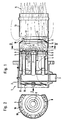
Bei dem in Fig. 1 dargestellten Brennerkopf 1 eines Gebläsegasbrenners ist das eigentliche Verbrennungsluftgebläse mit Motor und Ventilatorrad nicht dargestellt, sondern lediglich der Teil 2 des Gasbrennergehäuses, der zum Brennerkopf gehört, also der unmittelbar an den Heizkessel mit Brennraum angeschlossen wird. Die Verbrennungsluft wird über das im übrigen nicht dargestellte Brennergehäuse in Richtung des Pfeiles I dem Brennerkopf 1 zugeführt. Das Brenngas wird über eine Gasleitung 3 hier radial dem Brennerkopf 1 zugeführt und innerhalb desselben über eine rohrförmige Verteilereinrichtung 4 weitergeleitet. Die rohrförmige Verteilereinrichtung ist in Richtung Brennraum durch einen Brennerring 5 sowie eine Brennerplatte 6 abgeschlossen. Zwischen der Brennerplatte 6 und dem Brennerring 5 sind radiale Brenngasdüsen 7 vorhanden für einen quer zur Brennerkopfachse vorgesehenen Austritt des Brenngases. An dem Brennerring 5 sind auf der von der Verbrennungsluft angeströmten Seite Kanten 8 an Luftdurchgangsöffnungen 9 vorhanden, wobei diese Kanten 8 sogenannte Toruswirbel erzeugen, in die die aus den Brenngasdüsen 7 austretenden Brenngassträhnen angesaugt werden und intensiv mit der rotierenden Verbrennungsluft vermischt werden. In diesem Bereich der in Fig. 1 angedeuteten Wirbel stromab des Brennerrings beginnen die Flammenwurzeln einer kurzen Brennerflamme, ohne daß dafür zusätzliche Staubleche erforderlich sind. Eine der Luftdurchgangsöffnungen 9 ist als Ringspalt ausgebildet zwischen dem Brennerring 5 und einem über den Brennerring 5 und die rohrförmige Verteilereinrichtung 4 gesteckten Brennrohr 10, das in das Gehäuse 2 des Gasbrenners radial dichtend gesteckt und an diesem befestigt ist.In the burner head 1 of a fan gas burner shown in Fig. 1, the actual combustion air blower with motor and fan wheel is not shown, but only part 2 of the gas burner housing which belongs to the burner head, i.e. which is connected directly to the boiler with the combustion chamber. The combustion air is supplied to the burner head 1 in the direction of arrow I via the burner housing, which is otherwise not shown. The fuel gas is fed radially to the burner head 1 here via a gas line 3 and passed on within it via a
Auf dem dem Brennraum zugewandten Ende des Brennrohrs 10 ist an diesem ein Stegring 11 befestigt, der radial nach innen in die Flamme ragende Stege 12 aufweist. Mit Abstand ist an dem Brennrohr 10 ein Flammrohr 13, hier beispielhaft gleichen Durchmessers befestigt, welches den ersten Teil der Brennerflamme 14 umhüllt und wobei, ausgenommen an den Stellen, an denen Befestigungslaschen 15 angeordnet sind, ein Ringspalt 16 zwischen dem Brennrohr 10 und dem Flammrohr 13 entsteht, durch den aus der Brennkammer des Kessels Abgase wieder in das Flammrohr rezirkulieren können. Das Flammrohr 13 könnte auch einen größeren Durchmesser haben als das Brennrohr 10.On the end of the
Der Stegring 11 mit den Stegen 12 bewirkt eine leichte Einschnürung des vorbeiströmenden Flammenmassenstroms, was eine leichte Beschleunigung der Strömungsgeschwindigkeit zur Folge hat, bei gleichzeitiger leichter Ablenkung radial nach innen, so daß sich an den Stegen 12 "stehende" Wirbel bilden, die zur Ansaugung der Abgase aus dem Ringspalt 16 und somit zur Abgasrezirkulation führen, und die zudem durch die Injektorwirkung des Flammenmassenstroms im Flammrohr 13 unterstützt werden. Durch den Stegring 11 wird außerdem die an der Wand des Brennrohres 10 über die Luftdurchgangsöffnungen 9 zuströmende kühle Verbrennungsluft teilweise in das Flammzentrum geleitet, wodurch mit den ebenfalls zwischenzeitlich leicht abgekühlten sauerstoffärmeren rezirkulierenden Abgasen eine Absenkung der Flammentemperaturen erzielt wird, mit der entsprechenden Reduzierung des NOx-Anteils bis zu unter 40 ppm.The
Stromauf der Verteilereinrichtung 4 ist im Brennerkopf 1 eine Wirbelscheibe 17 angeordnet, die nahezu den Durchmesser des Brennrohres 10 aufweist, und durch deren schräg zueinander verstellte Segmente 18 eine schraubenförmige Drallbewegung der Verbrennungsluft erzielt wird.Upstream of the
Wie Fig. 2 entnehmbar ist, sind im Randbereich des Brennerrings 5 die Luftdurchgangsöffnungen 9 abschnittsweise vergrößernde Scharten 19 vorgesehen, die einen entsprechenden Einfluß auf die Geschwindigkeit des Verbrennungsluftstroms haben und in Verbindung mit der durch die Wirbelscheibe 17 bewirkten Drall des Luftstroms eine Verbesserung der Toruswirbel und der Brenngas/Verbrennungsluftgemischaufbereitung bewirken.As can be seen in FIG. 2, in the edge region of the
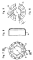
Bei dem in Fig. 3 in der Draufsicht dargestellten Stegring 11 mit Stegen 12 verbleibt zwischen den freien Enden 22 der Stege 12 ein freier Innendurchmesser d, welcher in einem bestimmten Verhältnis zum Außendurchmesser D und zur Ringbreite b des äußeren, nicht durchbrochenen Abschnitts 21 des Stegrings steht. Die Stege 12 sind als Blechfahnen der Breite B ausgebildet, die mit ihrem Stegfuß 20 gleichmäßig und in einer ebenen Fläche am äußeren Ringabschnitt 21 des Stegringes 11 verteilt sind und abgerundet in den Abschnitt 21 übergehen. Die Länge der Stege zwischen den freien Enden 22 bis hin zum Stegfuß ist mit L begzeichnet. Durch diese Gestaltung weisen die Durchgangsöffnungen 23 des Stegrings 11 zwischen den Stegen 12 einen tropfenförmigen, sich radial nach außen erweiternden und zum Innendurchmesser des Stegrings 11 offenen Querschnitt auf.In the
In den Fig. 5 und 6 ist je ein Schnitt durch den Stegring 11 gemäß der Linie V-V gezeigt, wobei entnehmbar ist, daß die Stege 12 in ihrem Längsverlauf einen Knick aufweisen, so daß sie einen rechtwinklig zur Brennerkopfachse verlaufenden Endabschnitt 24 und einen schräg zur Brennerkopfachse verlaufenden Fußabschnitt 25 aufweisen. Der Fußabschnitt 25 geht in den kegelförmigen äußeren Ringabschnitt 21 über, an den sich ein zylindrischer Rohrabschnitt 26 anschließt, mit welchem der Stegring 11 an das Brennrohr 10 gesteckt ist. Bei der in Fig. 5 dargestellten Variante ist dieser Rohrabschnitt 26 im Durchmesser größer als das Brennrohr 10 und ist somit auf dieses gesteckt, hingegen bei der Variante nach Fig. 6 ist dieser Rohrabschnitt 26 kleiner im Durchmesser und damit in das Brennrohr 10 gesteckt und an diesem befestigt. Für die gewünschte Abgasrezirkulation bei gleichzeitiger Erhaltung der günstigen Verbrennung spielt die Zuordnung der einzelnen Abmessungen D, d, L, B, b, die Neigung des Fußabschnitts 25 und die des äußeren Ringabschnittes 21 eine maßgebliche Rolle.5 and 6, a section through the
Bei der in Fig. 4 dargestellten Variante des Stegrings 11 mit Stegen 12 sind die seitlichen Begrenzungen der blechfahnenförmigen Stege 12 bis zum Stegfuß 20 hin parallel ausgebildet, und es sind auch die Grundkanten 27 der Durchgangsöffnungen 23, durch die die Stegfüße 20 miteinander verbunden sind, geradlinig ausgeführt, so daß der Querschnitt der Durchgangsöffnungen 23 bei dieser Variante die Form eines oben offenen Trapezes hat.In the variant of the
Eine weitere Variante des Stegringes 11 ist in den Figuren 7 und 8 gezeigt, bei dem an dem ebenfalls einteiligen, aus Rohrabschnitt 26 und äußerem, nicht durchbrochenen Ringabschnitt 21 gebildeten Stegring Blechlappen 28 sternförmig nach innen ragend befestigt, z.B. punktgeschweißt oder angenietet, sind. Der verbleibende Durchgangsquerschnitt der so gebildeten Durchgangsöffnungen 23 entspricht jenen der in Fig. 4 dargestellten Variante.A further variant of the
Eine andere Gestaltung des Stegrings 11 ist in den Fig. 9 und 10 dargestellt, bei denen der Stegring jeweils als Lochblech ausgebildet ist, mit in Fig. 9 ovalen Durchgangsöffnungen 23 und in Fig. 10 rechteckigen Durchgangsöffnungen 23.Another design of the
Der erfindungsgemäße Brennerkopf arbeitet wie folgt: dem über die radial nach innen und außen verlaufenden Brenngasdüsen 7 des Brennerrings 5 austretenden Brenngas wird Verbrennungsluft über die Luftdurchgangsöffnungen 9 und die Scharten 19 zugemischt, so daß in der Flammwurzel, also stromauf des Stegringes, für die Verbrennung Gemische zur Verfügung stehen unterschiedlicher Gaskonzentration. Während nahe der Luftdurchgangsöffnungen 9 und 19 mit sehr hohem Luftüberschuß verbrannt wird, erfolgt die Verbrennung in der Nähe der Brenngasdüsen 7 unter Luftmangel. In beiden Fällen bleibt deshalb die Verbrennungstemperatur niedrig, so daß eine sehr geringe NOx-Emission bei jedem dieser Teilflammen besteht. Erst im anschließenden Flammrohr 13 erfolgt die endgültige, vollständige Verbrennung mit der gewünschten Verminderung des CO-Anteils im Abgas. Da die Verbrennungsluft über die Wirbelscheibe 17 zusätzlich verdrallt wird, besteht eine Intensivierung bei der Vermischung des einerseits zu mageren, andererseits zu fetten Gasluftgemisches, so daß eine für das gewünschte Ziel noch ausreichende Verbrennung stromauf des Stegringes 11 erreicht wird. Durch das über die Scharten 19 erreichte luftimpulsartige Auftreffen der über die Wirbelscheibe 17 gedrallten Flamme auf den Stegring 11 mit den Stegen 12 wird stromauf des Stegringes an dessen der Strömung entgegenstehenden Flächen eine Überdruckzone bewirkt, der auf der Stromabseite eine Unterdruckzone folgt. Diese Unterdruckzone, die entsprechend der Gestaltung der Stegringe 11 zum Ringspalt 16 hin offen ist, bewirkt ein Hereinziehen der das Brennrohr 10 und das Flammrohr 13 umgebenden Abgase, so daß eine gewünschte Abgasrezirkulation entsteht. Das Abgas wird somit durch die durch die Stege 12 gebildeten Zwischenräume in die Flamme hineingeleitet und wirkt flammtemperatursenkend und dadurch NOx-mindernd. Außerdem wird auch der CO-Anteil im Abgas vermindert, ganz abgesehen davon, daß der Stegring 11 eine bei Gasgebläsebrennern erwünschte Verankerung der Flamme bewirkt, also ein Abreißen der Flamme verhindert. Endgültig ergibt sich aus dieser Zweistufenverbrennung mit Abgasrezirkulation der Vorteil, daß ein Gebläsegasbrenner mit dem erfindungsgemäßen Brennerkopf weitgehend unabhängig von der Gestaltung des Feuerraums eingesetzt werden kann.The burner head according to the invention works as follows: Combustion air is admixed via the
- 11
- BrennerkopfBurner head
- 22nd
- GehäuseteilHousing part
- 33rd
- GasleitungGas pipe
- 44th
- rohrförmige Verteilereinrichtungtubular distributor device
- 55
- BrennerringBurner ring
- 66
- BrennerplatteBurner plate
- 77
- BrenngasdüsenFuel gas nozzles
- 88th
- Kantenedge
- 99
- LuftdurchgangsöffnungenAir vents
- 1010th
- BrennrohrFuel tube
- 1111
- StegringWeb ring
- 1212
- StegeWalkways
- 1313
- FlammrohrFlame tube
- 1414
- BrennerflammeBurner flame
- 1515
- BefestigungslaschenMounting tabs
- 1616
- RingspaltAnnular gap
- 1717th
- WirbelscheibeVertebral disc
- 1818th
- SegmenteSegments
- 1919th
- SchartenNicks
- 2020th
- StegfußBridge foot
- 2121
- äußerer, nicht durchbrochener (Ring)Abschnitt,outer, non-perforated (ring) section,
- 2222
- freie Enden von 12free ends of 12
- 2323
- DurchgangsöffnungThrough opening
- 2424th
- EndabschnittEnd section
- 2525th
- FußabschnittFoot section
- 2626
- RohrabschnittPipe section
- 2727
- GrundkanteBase edge
- 2828
- BlechlappenSheet metal rag
Claims (16)
- Burner head for a ventilated gas burner with combustion pipe designed to hold a device for distributing the combustion gas and the combustion air, with combustion gas nozzles and air inlet/outlet openings, and with a flame-pipe connected to the combustion pipe characterised by at least one radial opening (16), serving for the recirculation of the exhaust gas, being present between the combustion pipe (10) and the flame-pipe (13), and by cross-members (12) which project inwards being present in the flame root area between the combustion tube (10) and the flame-pipe (13) upstream of the radial opening (16) but downstream of the combustion gas nozzles (7) and the air inlet/outlet openings (9, 19) and cross-wise to the longitudinal axis of the burner head.
- Burner head along the lines of Claim 1, characterised by the device for distributing the combustion gas having, in the manner of a cross-flow burner, a burner ring (5) mounted crosswise to the axis of the burner head and fitted with a burner plate (6), with combustion gas nozzles (7) arranged radially and air inlet/outlet openings arranged axially (9).
- Burner head along the lines of Claim 2 characterised by the periphery of the burner ring (5) having apertures (19) towards the combustion tube (10) as well as a ring slot in the form of notches as additional air inlet/outlet openings for the combustion air.
- Burner head along the lines of Claim 3 characterised by the notches (19) having an internal width of a quarter to one-third of the distance between the combustion gas nozzles (7) in the external row of the burner ring (5) on the side facing the notches (19).
- Burner head along the lines of one of the foregoing Claims characterised by a vortex plate (17) for the combustion air in the combustion tube (10) being fitted upstream of the device of the distribution of the combustion gas (4).
- Burner head along the lines of one of the foregoing Claims characterised by the cross-members (12) being arranged as baffles in the direction of the combustion air flowing in the inlet/outlet openings (9, 19).
- Burner head along the lines of one of the foregoing Claims characterised by the cross-members (12) being part of a ring of cross-members (11) with an external, non-perforated ring section (21) and with a cross-section which is determined by the existing inlet/outlet openings (23) between the cross-members (12) and the ring section (21).
- Burner head along the lines of Claim 7 characterised by the cross-member ring (11) having a central opening.
- Burner head along the lines of one Claims 7 or 8 characterised by the cross-member ring (11) being limited outwards by a cylindrical section of tube (26) corresponding with the diameter of the combustion tube (10) and being fastened to it.
- Burner head along the lines of one of the Claims 7 to 9 characterised by the radial limit edges of the cross-members (12) running parallel to one another with the length of the cross-member (L) being at least twice as great as its breadth (B).
- Burner head along the lines of Claim 10 characterised by the cross-members (12) being rounded and widened at the foot end (20) and the cross-members having free ends (22) radially inwards, so that the cross-section of the inlet/outlet openings (23) takes on the shape of a tear-drop (Fig. 3).
- Burner head along the lines of Claim 10 characterised by the inlet/outlet openings (23) in the cross-member ring (11) having a trapezium-shaped, rectangular, or long-slot cross-section (Figs. 4 to 10).
- Burner head along the lines of one of the Claims 8 to 12 characterised by the inlet/outlet openings (23) in the cross-member ring (11) being open towards the inner opening of the cross-member ring.
- Burner head along the lines of one of the Claims 7 to 13 characterised by the cross-members being formed as metal flaps (28) which are fastened to the outer, non-perforated section (21).
- Burner head along the lines of one of the Claims 7 to 14 characterised by the outer, non-perforated ring section (21) of the cross-member ring (11) having a conical shape which tapers away in the control direction.
- Burner head along the lines of Claim 15 characterised by at least one foot section (25) of the cross-members (12) have the same angle of inclination as the external ring section.
Priority Applications (1)
| Application Number | Priority Date | Filing Date | Title |
|---|---|---|---|
| AT89111185T ATE89390T1 (en) | 1988-06-21 | 1989-06-20 | BURNER HEAD FOR A PUSHED GAS BURNER. |
Applications Claiming Priority (2)
| Application Number | Priority Date | Filing Date | Title |
|---|---|---|---|
| DE3820849 | 1988-06-21 | ||
| DE3820849 | 1988-06-21 |
Publications (3)
| Publication Number | Publication Date |
|---|---|
| EP0347834A2 EP0347834A2 (en) | 1989-12-27 |
| EP0347834A3 EP0347834A3 (en) | 1991-07-24 |
| EP0347834B1 true EP0347834B1 (en) | 1993-05-12 |
Family
ID=6356881
Family Applications (1)
| Application Number | Title | Priority Date | Filing Date |
|---|---|---|---|
| EP89111185A Expired - Lifetime EP0347834B1 (en) | 1988-06-21 | 1989-06-20 | Burner head for a forced-draft gas burner |
Country Status (4)
| Country | Link |
|---|---|
| US (1) | US5015174A (en) |
| EP (1) | EP0347834B1 (en) |
| AT (1) | ATE89390T1 (en) |
| DE (1) | DE58904315D1 (en) |
Cited By (3)
| Publication number | Priority date | Publication date | Assignee | Title |
|---|---|---|---|---|
| DE102007009922A1 (en) | 2007-02-27 | 2008-08-28 | Ulrich Dreizler | Liquid or gaseous fuel combusting method for combustion chamber, involves arranging individual flames, such that common flame forms hollow flame with appropriate hollow space downstream to baffle plate |
| US7891971B2 (en) | 2005-08-16 | 2011-02-22 | Elco Burners Gmbh | Combustion head and method for combusting fuel |
| CN109442399A (en) * | 2018-07-20 | 2019-03-08 | 北京航空航天大学 | One kind, which liquidates, directly sprays low NO |
Families Citing this family (18)
| Publication number | Priority date | Publication date | Assignee | Title |
|---|---|---|---|---|
| DE3942747A1 (en) * | 1989-12-22 | 1991-06-27 | Eberspaecher J | VEHICLE HEATER, ESPECIALLY MOTOR VEHICLE ADDITIONAL HEATER |
| DE4002237A1 (en) * | 1990-01-26 | 1991-08-01 | Elco Energiesysteme Gmbh | Gas burner combustion chamber - has exhaust gas feed component from furnace mounted concentrically in burner tube |
| US5413477A (en) * | 1992-10-16 | 1995-05-09 | Gas Research Institute | Staged air, low NOX burner with internal recuperative flue gas recirculation |
| US5269679A (en) * | 1992-10-16 | 1993-12-14 | Gas Research Institute | Staged air, recirculating flue gas low NOx burner |
| EP0612959A1 (en) * | 1993-02-23 | 1994-08-31 | D.W. Clysan B.V. | Venturi burner |
| DE9321525U1 (en) * | 1993-07-20 | 1999-01-28 | Elco Kloeckner Heiztech Gmbh | Burners for the combustion of liquid or gaseous fuels in combustion plants |
| ATE173076T1 (en) * | 1994-09-28 | 1998-11-15 | Abig Werke Carry Gross Gmbh | BURNER HEAD INSERT |
| US5957682A (en) * | 1996-09-04 | 1999-09-28 | Gordon-Piatt Energy Group, Inc. | Low NOx burner assembly |
| US5839891A (en) * | 1997-01-13 | 1998-11-24 | Beckett Gas, Inc. | Power gas burner |
| EP0867659A1 (en) * | 1997-03-24 | 1998-09-30 | VTH Verfahrentechnik für Heizung AG | Process and device for combustion of gaseous fuel |
| DE19813336C2 (en) * | 1998-03-26 | 2002-08-01 | Viessmann Werke Kg | Burners for liquid fuels |
| ITBO20010178A1 (en) * | 2001-03-26 | 2002-09-26 | Riello Spa | BURNER |
| DE102005026649A1 (en) * | 2005-06-09 | 2006-12-28 | Robert Bosch Gmbh | Burner for liquid fuels |
| SE537347C2 (en) | 2012-08-31 | 2015-04-07 | Reformtech Heating Holding Ab | Combustion apparatus |
| EP3274101B1 (en) * | 2015-03-23 | 2021-02-24 | Stamford Devices Limited | An aerosol generator |
| IT202000028400A1 (en) * | 2020-11-25 | 2022-05-25 | Baltur S P A | BURNER AND INDUSTRIAL EQUIPMENT WITH REDUCED EMISSIONS |
| CN217131272U (en) * | 2020-11-25 | 2022-08-05 | 百得股份公司 | Reduced emission industrial combustor and apparatus |
| IT202000028394A1 (en) * | 2020-11-25 | 2022-05-25 | Baltur S P A | BURNER AND INDUSTRIAL EQUIPMENT WITH REDUCED EMISSIONS |
Family Cites Families (7)
| Publication number | Priority date | Publication date | Assignee | Title |
|---|---|---|---|---|
| US2518937A (en) * | 1946-06-22 | 1950-08-15 | Premix Comb Inc | Head structure for gun type oil burners |
| FR1507416A (en) * | 1967-01-03 | 1967-12-29 | Etablissements Ch Thuel Soc D | Combustion head for gas burners, as well as burners provided with this head |
| NL153322B (en) * | 1968-11-28 | 1977-05-16 | Kleis Van Der Giesen | GAS BURNER. |
| US3589845A (en) * | 1969-04-23 | 1971-06-29 | Adams Mfg Co The | Power burner |
| BE755352A (en) * | 1969-09-05 | 1971-03-01 | Shell Int Research | COMBUSTION DEVICE FOR GAS FUEL |
| DE2318355A1 (en) * | 1973-04-12 | 1974-10-24 | Junkers & Co | GAS AND OIL BURNERS |
| ATE39746T1 (en) * | 1985-06-12 | 1989-01-15 | Georg Pletzer | FIRING DEVICE. |
-
1989
- 1989-06-20 EP EP89111185A patent/EP0347834B1/en not_active Expired - Lifetime
- 1989-06-20 AT AT89111185T patent/ATE89390T1/en not_active IP Right Cessation
- 1989-06-20 DE DE8989111185T patent/DE58904315D1/en not_active Expired - Lifetime
- 1989-06-21 US US07/369,446 patent/US5015174A/en not_active Expired - Fee Related
Cited By (4)
| Publication number | Priority date | Publication date | Assignee | Title |
|---|---|---|---|---|
| US7891971B2 (en) | 2005-08-16 | 2011-02-22 | Elco Burners Gmbh | Combustion head and method for combusting fuel |
| DE102007009922A1 (en) | 2007-02-27 | 2008-08-28 | Ulrich Dreizler | Liquid or gaseous fuel combusting method for combustion chamber, involves arranging individual flames, such that common flame forms hollow flame with appropriate hollow space downstream to baffle plate |
| EP2126471B1 (en) | 2007-02-27 | 2016-02-10 | Ulrich Dreizler | Hollow flame |
| CN109442399A (en) * | 2018-07-20 | 2019-03-08 | 北京航空航天大学 | One kind, which liquidates, directly sprays low NO |
Also Published As
| Publication number | Publication date |
|---|---|
| DE58904315D1 (en) | 1993-06-17 |
| EP0347834A3 (en) | 1991-07-24 |
| US5015174A (en) | 1991-05-14 |
| ATE89390T1 (en) | 1993-05-15 |
| EP0347834A2 (en) | 1989-12-27 |
Similar Documents
| Publication | Publication Date | Title |
|---|---|---|
| EP0347834B1 (en) | Burner head for a forced-draft gas burner | |
| EP0794383B1 (en) | Method of operating a pressurised atomising nozzle | |
| DE3217674C2 (en) | Combustion chamber for a gas turbine | |
| EP0620403B1 (en) | Mixing and flame stabilizing device in a combustion chamber with premixing combustion | |
| EP0629817B1 (en) | Furnace | |
| EP0777081B1 (en) | Premix burner | |
| EP0580683A1 (en) | Burner arrangement, especially for gas turbines, for the low-pollutant combustion of coal gas and other fuels. | |
| DE4223828A1 (en) | Method for operating a combustion chamber of a gas turbine | |
| DE3007763A1 (en) | BURNING DEVICE FOR GAS TURBINE ENGINES | |
| EP0641971B1 (en) | Method for operating a premix burner and premix burner for execution of the method | |
| WO2008155373A1 (en) | Non-rotational stabilization of the flame of a premixing burner | |
| EP0394800B1 (en) | Premix burner for generating a hot gas | |
| DE19627760C2 (en) | Burner with atomizer nozzle | |
| DE2261596B2 (en) | Method and combustion chamber for burning a fuel | |
| EP0742411B1 (en) | Air supply for a premix combustor | |
| EP0783089B1 (en) | Cone-shaped burner | |
| EP0483554B1 (en) | Method for minimising the NOx emissions from a combustion | |
| EP1130315A2 (en) | Atmospheric gas burner | |
| EP0052191A2 (en) | Atmospheric gas burner, especially for gas-heated home appliances | |
| DE4324298C2 (en) | Process for the combustion of liquid or gaseous fuels in combustion plants and burners for carrying out the process | |
| DE3741021C2 (en) | Combustion chamber for a gas turbine engine | |
| DE19545036A1 (en) | Premix burner | |
| DE3920078A1 (en) | Burner head for a blower gas burner | |
| EP0491079B1 (en) | Burner head for premix combustion of a liquid fuel in an atmospheric combustion installation | |
| EP0730121A2 (en) | Premix burner |
Legal Events
| Date | Code | Title | Description |
|---|---|---|---|
| PUAI | Public reference made under article 153(3) epc to a published international application that has entered the european phase |
Free format text: ORIGINAL CODE: 0009012 |
|
| AK | Designated contracting states |
Kind code of ref document: A2 Designated state(s): AT BE CH DE ES FR GB GR IT LI LU NL SE |
|
| PUAL | Search report despatched |
Free format text: ORIGINAL CODE: 0009013 |
|
| AK | Designated contracting states |
Kind code of ref document: A3 Designated state(s): AT BE CH DE ES FR GB GR IT LI LU NL SE |
|
| 17P | Request for examination filed |
Effective date: 19910924 |
|
| 17Q | First examination report despatched |
Effective date: 19921023 |
|
| GRAA | (expected) grant |
Free format text: ORIGINAL CODE: 0009210 |
|
| AK | Designated contracting states |
Kind code of ref document: B1 Designated state(s): AT BE CH DE ES FR GB GR IT LI LU NL SE |
|
| PG25 | Lapsed in a contracting state [announced via postgrant information from national office to epo] |
Ref country code: BE Effective date: 19930512 Ref country code: ES Free format text: THE PATENT HAS BEEN ANNULLED BY A DECISION OF A NATIONAL AUTHORITY Effective date: 19930512 Ref country code: GR Free format text: LAPSE BECAUSE OF FAILURE TO SUBMIT A TRANSLATION OF THE DESCRIPTION OR TO PAY THE FEE WITHIN THE PRESCRIBED TIME-LIMIT Effective date: 19930512 Ref country code: GB Effective date: 19930512 Ref country code: SE Effective date: 19930512 |
|
| REF | Corresponds to: |
Ref document number: 89390 Country of ref document: AT Date of ref document: 19930515 Kind code of ref document: T |
|
| REF | Corresponds to: |
Ref document number: 58904315 Country of ref document: DE Date of ref document: 19930617 |
|
| PG25 | Lapsed in a contracting state [announced via postgrant information from national office to epo] |
Ref country code: AT Effective date: 19930620 |
|
| PG25 | Lapsed in a contracting state [announced via postgrant information from national office to epo] |
Ref country code: LU Free format text: LAPSE BECAUSE OF NON-PAYMENT OF DUE FEES Effective date: 19930630 Ref country code: LI Effective date: 19930630 Ref country code: CH Effective date: 19930630 |
|
| ITF | It: translation for a ep patent filed |
Owner name: DE DOMINICIS & MAYER S.R.L. |
|
| ET | Fr: translation filed | ||
| GBV | Gb: ep patent (uk) treated as always having been void in accordance with gb section 77(7)/1977 [no translation filed] |
Effective date: 19930512 |
|
| REG | Reference to a national code |
Ref country code: CH Ref legal event code: PL |
|
| PGFP | Annual fee paid to national office [announced via postgrant information from national office to epo] |
Ref country code: DE Payment date: 20080418 Year of fee payment: 20 Ref country code: NL Payment date: 20080618 Year of fee payment: 20 |
|
| PGFP | Annual fee paid to national office [announced via postgrant information from national office to epo] |
Ref country code: FR Payment date: 20080618 Year of fee payment: 20 Ref country code: IT Payment date: 20080627 Year of fee payment: 20 |
|
| PG25 | Lapsed in a contracting state [announced via postgrant information from national office to epo] |
Ref country code: NL Free format text: LAPSE BECAUSE OF EXPIRATION OF PROTECTION Effective date: 20090620 |
|
| NLV7 | Nl: ceased due to reaching the maximum lifetime of a patent |
Effective date: 20090620 |
|
| PLBE | No opposition filed within time limit |
Free format text: ORIGINAL CODE: 0009261 |
|
| STAA | Information on the status of an ep patent application or granted ep patent |
Free format text: STATUS: NO OPPOSITION FILED WITHIN TIME LIMIT |