EP0612959A1 - Venturi burner - Google Patents
Venturi burner Download PDFInfo
- Publication number
- EP0612959A1 EP0612959A1 EP94200429A EP94200429A EP0612959A1 EP 0612959 A1 EP0612959 A1 EP 0612959A1 EP 94200429 A EP94200429 A EP 94200429A EP 94200429 A EP94200429 A EP 94200429A EP 0612959 A1 EP0612959 A1 EP 0612959A1
- Authority
- EP
- European Patent Office
- Prior art keywords
- burner
- gas
- outlet openings
- series
- gas outlet
- Prior art date
- Legal status (The legal status is an assumption and is not a legal conclusion. Google has not performed a legal analysis and makes no representation as to the accuracy of the status listed.)
- Withdrawn
Links
Images


Classifications
-
- F—MECHANICAL ENGINEERING; LIGHTING; HEATING; WEAPONS; BLASTING
- F23—COMBUSTION APPARATUS; COMBUSTION PROCESSES
- F23D—BURNERS
- F23D14/00—Burners for combustion of a gas, e.g. of a gas stored under pressure as a liquid
- F23D14/34—Burners specially adapted for use with means for pressurising the gaseous fuel or the combustion air
- F23D14/36—Burners specially adapted for use with means for pressurising the gaseous fuel or the combustion air in which the compressor and burner form a single unit
-
- F—MECHANICAL ENGINEERING; LIGHTING; HEATING; WEAPONS; BLASTING
- F23—COMBUSTION APPARATUS; COMBUSTION PROCESSES
- F23D—BURNERS
- F23D14/00—Burners for combustion of a gas, e.g. of a gas stored under pressure as a liquid
- F23D14/20—Non-premix gas burners, i.e. in which gaseous fuel is mixed with combustion air on arrival at the combustion zone
- F23D14/22—Non-premix gas burners, i.e. in which gaseous fuel is mixed with combustion air on arrival at the combustion zone with separate air and gas feed ducts, e.g. with ducts running parallel or crossing each other
-
- F—MECHANICAL ENGINEERING; LIGHTING; HEATING; WEAPONS; BLASTING
- F23—COMBUSTION APPARATUS; COMBUSTION PROCESSES
- F23C—METHODS OR APPARATUS FOR COMBUSTION USING FLUID FUEL OR SOLID FUEL SUSPENDED IN A CARRIER GAS OR AIR
- F23C2201/00—Staged combustion
- F23C2201/20—Burner staging
-
- F—MECHANICAL ENGINEERING; LIGHTING; HEATING; WEAPONS; BLASTING
- F23—COMBUSTION APPARATUS; COMBUSTION PROCESSES
- F23C—METHODS OR APPARATUS FOR COMBUSTION USING FLUID FUEL OR SOLID FUEL SUSPENDED IN A CARRIER GAS OR AIR
- F23C2201/00—Staged combustion
- F23C2201/30—Staged fuel supply
-
- F—MECHANICAL ENGINEERING; LIGHTING; HEATING; WEAPONS; BLASTING
- F23—COMBUSTION APPARATUS; COMBUSTION PROCESSES
- F23C—METHODS OR APPARATUS FOR COMBUSTION USING FLUID FUEL OR SOLID FUEL SUSPENDED IN A CARRIER GAS OR AIR
- F23C2202/00—Fluegas recirculation
- F23C2202/30—Premixing fluegas with combustion air
-
- F—MECHANICAL ENGINEERING; LIGHTING; HEATING; WEAPONS; BLASTING
- F23—COMBUSTION APPARATUS; COMBUSTION PROCESSES
- F23D—BURNERS
- F23D2900/00—Special features of, or arrangements for burners using fluid fuels or solid fuels suspended in a carrier gas
- F23D2900/14—Special features of gas burners
- F23D2900/14003—Special features of gas burners with more than one nozzle
Definitions
- the invention relates to a burner, in particular a gas-fired fan burner for a central heating installation.
- Such a burner comprising a substantially cylindrical burner housing, of which one end, being the outlet end, is connectable to an opening in a furnace wall of a central heating boiler, while to the other end thereof, being the inlet end of the burner housing, a burner fan for forced supply of combustion air and a fuel supply line are connectable, a mixing tube extending concentrically within the burner housing and connecting to a burner head at the outlet end of the burner housing, which burner head, in mounted condition of the burner, extends into the furnace by a flame cup surrounding the burner head, while an annular space between the burner housing wall and the mixing tube is in open communication with the furnace at the outlet end and with the inner space of the mixing tube at the inlet end of the burner housing, is described as a burner for liquid fuel in U.S. patent specification 3,741,166.
- combustion air is blown by the fan in a forced manner through the mixing tube to the burner head, while fuel is supplied to the burner head.
- the combustible mixture is combusted at the burner head, the flame being stabilized within the flame cup. Due to the pressure prevailing in the furnace and also due to the underpressure created in the mixing tube by the air flowing through, a portion of the combustion or flue gases is returned from the furnace via the annular channel and mixed with the combustion air in the mixing tube.
- the flue gas thus recirculated reduces the partial oxygen pressure, thereby increasing the heat capacity of the flue gas and reducing the flame temperature.
- a reduction of the NO x emission is achieved.
- the flue gas recirculation does not decrease in proportion to the air flow rate when the burner is modulated, for instance adjusted from full load to partial load.
- An excess of recirculated flue gas (more than 20-30%) has an adverse effect on the combustion process and may cause an unstable flame.
- the burner housing construction were used in gas burners of the type as described in NL patent No. 153322, where the burner head is designed as one or more concentric, hollow gas-conducting rings round which axially supplied air flows, each ring having gas outlet openings in a plane perpendicular to the burner axis and distributed in circumferential direction, while upstream of the gas outlet openings flange-shaped radial projections have been provided forming vortex elements promoting the gas/air mixture, the outflowing air may also meet with so much resistance that even in the case of full load more flue gas is being recirculated than is desirable for a stable combustion with low NO x emission.
- the object of the invention is to provide a gas burner of the type described in the preamble, in which the above-mentioned drawbacks of the known burner are avoided.
- the inner side of the mixing tube in the burner chamber is designed as a venturi.
- Air injected by the fan at the inlet end of the mixing tube is compressed in the venturi throat and, after the throat, expanded over a particular distance. Due to the underpressure generated thereby, substantially proportional to the air flow rate, flue gas is drawn in from the furnace via the annular channel and mixed with through-flowing air in the mixing tube. From the furnace to the inlet in the mixing tube, the recirculated flue gas is cooled (from approx. 1,000°C to approx. 600°C), and at the burner head a flue gas/air mixture of relatively low temperature is delivered to be mixed with combustion gas, which contributes to the reduction of the flame temperature and hence to a reduction of the NO x emission.
- the percentage of flue gas in the combustion air can be kept the same at full load and partial load, so that the NO x reduction remains the same throughout the entire control range.
- the blow-in speed at the inlet of the venturi, and hence the amount of recirculated flue gas, can be controlled without having to deploy a fan with adjustable rotational speed.
- the burner may comprise an intermediate ring, accommodated concentrically in the burner housing, downstream from the air injection nozzle and upstream from the mixing tube inlet, which intermediate ring is provided with a flange.
- the burner head may be adapted for two-stage combustion, by providing, in addition to a first series of gas outlet openings, a second series of gas outlet openings downstream from the first series.
- the amount of air supplied via the mixing tube is sufficient for combusting a specific amount of gas. As only a portion of this gas amount flows out via the first series of gas outlet openings, an excess of air is present at that location. The relatively large amount of air can take up heat of the flames at the first series of gas outlet openings. The combustion air is consumed entirely only at the second series of gas outlet openings. Because the second, downstream combustion zone is located in the vicinity of the open end of the flame cup, the heat developed at that location can quickly be delivered to the furnace. In total, this yields a significant reduction of the flame temperature and, accordingly, a reduction of the NO x emission.
- the gas outlet openings are adjusted such that at the first series approx. 25% and at the second series approx. 75% of the gas flows out.
- one or several hollow gas-conducting rings may be provided with tubes, directed downstream, whose ends are closed off, which tubes, in the vicinity of the closed ends thereof, comprise gas outlet openings in a plane perpendicular to the burner axis, forming the second series of gas outlet openings.
- the tubes and/or gas-conducting rings may be provided with axial, plate-shaped elements increasing the heated surface, which elements have a cooling effect on the air and the flue gases from the first combustion stage flowing past.
- the furnace wall through which, in mounted condition, a burner extends, is covered with a fire-resisting brickwork at the furnace side thereof.
- the burner housing at the outlet end thereof, may be extended by an outer flame cup which, when the burner is in mounted condition, extends into the furnace and surrounds the mixing tube at a radial distance.
- Fig. 1 shows a boiler 1 with a burner 3 connected to the boiler front 2, which burner comprises a burner housing 4 and an air supply fan 5.
- the boiler comprises a furnace 6, a heat exchanger 7 and a flue gas discharge 8.
- the burner housing 4 of the burner 3 is connected to an opening in the boiler front 2 by an outlet end 9 and to the blow-out opening 11 of the air supply fan 5 by the inlet end 10.
- the burner 3, shown in detail in Figs 2 and 3 comprises a mixing tube 12, extending concentrically within the burner housing 4 and connecting to a burner head 13 at the outlet end of the burner housing 4.
- the burner head 13 is surrounded by a flame cup 14.
- the burner head 13 and the flame cup 14 extend into the furnace 6 of the boiler 1.
- an annular space 15 Located between the burner housing 4 and the mixing tube 12 is an annular space 15, being in open communication with the furnace 6 at the outlet end and with the inner space 16 of the mixing tube 12 at the inlet end of the burner housing 4.
- the fan 5 blows combustion air into the inner space 16 of the mixing tube 12.
- the flow rate of the combustion air at the inlet of the mixing tube 12 depends on the distance of the injection nozzle 17 from the inlet of the mixing tube 12. In the case of a greater distance, the combustion air must travel a greater distance before it reaches the mixing tube 12 and, accordingly, has a lower flow rate at the inlet of the mixing tube 12.
- the injection nozzle 17 being axially adjustable, the fan 5 need only be designed for rotation at a fixed speed.
- the fuel is supplied via the fuel connection 18 and passed to the burner head 13 via a fuel channel 19.
- the mixing tube 12 is designed as a venturi. As the combustion air coming from the fan 5 is compressed in the venturi and, after the throat, expanded over a particular distance, an underpressure is produced at the venturi inlet which is proportional to the combustion air flow rate. Due to the underpressure and the overpressure prevailing in the furnace 6, a portion of the flue gas is conducted via the annular space from the furnace 6 to the inlet of the mixing tube 12. Mixture of the combustion air with flue gas reduces the partial oxygen pressure of the combustion air, so that the heat capacity of the flue gas is increased and, accordingly, the flame temperature is reduced, so that the NO x emission is reduced. As the underpressure in the mixing tube 12 is substantially proportional to the combustion air flow rate, the amount of flue gas that is recirculated will decrease proportionally to the combustion air flow rate even when the burner 3 is modulated.
- Figs 6 and 7 show an alternative exemplary embodiment of the burner according to the invention, wherein the parts with the same function as the parts of the exemplary embodiment shown in Figs 2 and 3 are designated by the same reference numerals.
- the alternative exemplary embodiment comprises an intermediate ring 28, accommodated concentrically in the burner housing 4 downstream from the air injection nozzle 17 and upstream from the mixing tube inlet 12, which intermediate ring 28 comprises a flange 29.
- the flange 29, extending perpendicularly to the burner housing center line in the exempary embodiment shown, may be funnel-shaped, the wide mouth of the funnel being directed to the injection nozzle 17.
- Such design of the flange 29 reduces the chance of combustion air, injected via air injector 17, being blown directly into the boiler furnace via the annular space 15 round the venturi 12.
- the burner head 13 comprises two concentric burner rings 20, 21, the inner ring being designed as a burner plate 21.
- the flue gas/combustion air mixture flows round the burner ring 20 and the burner plate 21 in axial direction, i.e. in the direction of the burner axis.
- the burner ring 20 and the burner plate 21 comprise radial combustion medium outlet openings 22 which are directed radially, i.e. perpendicularly to the burner axis. Arranged upstream from these outlet openings are radial projections 23 promoting the fuel/air mixture by causing a vortex in the combustion air.
- Such burner head provides a stable flame front.
- an alternative burner head 13a is proposed, shown in detail in Figs 4 and 5.
- the burner head 13a is designed for two-stage combustion in that, in addition to the fuel outlet openings 22a of the or each burner ring 20a, a second series of fuel outlet openings 24 is arranged downstream therefrom.
- this is realized through the arrangement of tubes 25, directed axially downstream, on the outer burner ring 20a, which tubes 25 are closed at the outer ends thereof and which comprise radially directed outlet openings 24.
- radial projections are provided for obtaining a proper mixture, created by vortex, between the outflowing gas and the combustion air.
- the flow-through surface of the first series of outlet openings 22a is 25% and the flow-through area of the second series of outlet openings 24 is 75% of the total flow-through area.
- an excess of air is present at that location.
- the relatively large amount of air can take up the heat of the flames at the hollow rings.
- the combustion air is consumed entirely.
- the second, downstream combustion zone is located in the vicinity of the open end of the flame cup 14, the heat developed at that location can be delivered directly to the furnace 6. In total, this yields a significant reduction of the flame temperature and, accordingly, a reduction of the NO x emission.
- the burner plate 21a and the tubes 25 comprise plate-shaped elements 26 and 26a, increasing the heated surface and having a cooling effect on the air and the flue gases from the first combustion zone flowing past.
- the burner housing 4 at the outlet side thereof, has been extended to include a flame cup 27, exending into the furnace 6 and surrounding mixing tube 12 at a radial distance.
Landscapes
- Engineering & Computer Science (AREA)
- Chemical & Material Sciences (AREA)
- Combustion & Propulsion (AREA)
- Mechanical Engineering (AREA)
- General Engineering & Computer Science (AREA)
Abstract
A gas-fired fan burner (3) for a central heating installation, comprising a cylindrical burner housing (4), a venturi (12) arranged concentrically within the housing, a burner fan (5) for the forced supply of combustion air, an injection nozzle (17) and a fuel supply line (19), the venturi connecting to a burner head and an annular space (15) between the burner housing wall and the venturi being in open communication with the furnace (6) and with the inlet of the venturi (16), the burner head (13) being designed as one or more concentric, hollow gas-conducting rings round which axially supplied air flows, each ring having gas outlet openings perpendicular to the burner axis and distributed in circumferential direction, there being provided flange-shaped gas/air mixture-promoting vortex elements upstream from the gas outlet openings, at least one hollow gas-conducting ring having downstream-directed tubes which also comprise gas outlet openings in a plane perpendicular to the burner axis, which openings are adjusted such that at the first series 25% and at the second series 75% of the gas flows out.
Description
- The invention relates to a burner, in particular a gas-fired fan burner for a central heating installation.
- Such a burner, comprising a substantially cylindrical burner housing, of which one end, being the outlet end, is connectable to an opening in a furnace wall of a central heating boiler, while to the other end thereof, being the inlet end of the burner housing, a burner fan for forced supply of combustion air and a fuel supply line are connectable, a mixing tube extending concentrically within the burner housing and connecting to a burner head at the outlet end of the burner housing, which burner head, in mounted condition of the burner, extends into the furnace by a flame cup surrounding the burner head, while an annular space between the burner housing wall and the mixing tube is in open communication with the furnace at the outlet end and with the inner space of the mixing tube at the inlet end of the burner housing, is described as a burner for liquid fuel in U.S. patent specification 3,741,166.
- When the known burner is in operation, combustion air is blown by the fan in a forced manner through the mixing tube to the burner head, while fuel is supplied to the burner head. The combustible mixture is combusted at the burner head, the flame being stabilized within the flame cup. Due to the pressure prevailing in the furnace and also due to the underpressure created in the mixing tube by the air flowing through, a portion of the combustion or flue gases is returned from the furnace via the annular channel and mixed with the combustion air in the mixing tube.
- When mixed with the combustion air, the flue gas thus recirculated reduces the partial oxygen pressure, thereby increasing the heat capacity of the flue gas and reducing the flame temperature. Thus, a reduction of the NOx emission is achieved.
- In the known burner, where both the burner housing and the mixing tube are cylindrical while the resistance of the furnace remains substantially the same, the flue gas recirculation does not decrease in proportion to the air flow rate when the burner is modulated, for instance adjusted from full load to partial load. An excess of recirculated flue gas (more than 20-30%) has an adverse effect on the combustion process and may cause an unstable flame.
- If the known burner housing construction were used in gas burners of the type as described in NL patent No. 153322, where the burner head is designed as one or more concentric, hollow gas-conducting rings round which axially supplied air flows, each ring having gas outlet openings in a plane perpendicular to the burner axis and distributed in circumferential direction, while upstream of the gas outlet openings flange-shaped radial projections have been provided forming vortex elements promoting the gas/air mixture, the outflowing air may also meet with so much resistance that even in the case of full load more flue gas is being recirculated than is desirable for a stable combustion with low NOx emission.
- The object of the invention is to provide a gas burner of the type described in the preamble, in which the above-mentioned drawbacks of the known burner are avoided.
- To this end, according to the invention, the inner side of the mixing tube in the burner chamber is designed as a venturi.
- Air injected by the fan at the inlet end of the mixing tube is compressed in the venturi throat and, after the throat, expanded over a particular distance. Due to the underpressure generated thereby, substantially proportional to the air flow rate, flue gas is drawn in from the furnace via the annular channel and mixed with through-flowing air in the mixing tube. From the furnace to the inlet in the mixing tube, the recirculated flue gas is cooled (from approx. 1,000°C to approx. 600°C), and at the burner head a flue gas/air mixture of relatively low temperature is delivered to be mixed with combustion gas, which contributes to the reduction of the flame temperature and hence to a reduction of the NOx emission.
- In the burner according to the invention, a higher or lower furnace and/or burner resistance hardly influences the transport of flue gases. Accordingly, the percentage of flue gas in the combustion air can be kept the same at full load and partial load, so that the NOx reduction remains the same throughout the entire control range.
- By mounting in the blow-out opening of the burner fan an air injection nozzle which is constricted relative to the cross-sectional area of the blow-out opening, air can be injected into the venturi at high speed.
- If the air injection nozzle is of an axially adjustable construction, the blow-in speed at the inlet of the venturi, and hence the amount of recirculated flue gas, can be controlled without having to deploy a fan with adjustable rotational speed.
- In a further elaboration of the invention, the burner may comprise an intermediate ring, accommodated concentrically in the burner housing, downstream from the air injection nozzle and upstream from the mixing tube inlet, which intermediate ring is provided with a flange.
- Due to the presence of the intermediate ring, flue gases are already drawn in before the combustion air is blown into the mixing tube. Consequently, a flue gas/air mixture is blown into the venturi, while due to the underpressure in the venturi, flue gases are once again drawn in by the venturi. This enables operation with an air injector having a larger cross-sectional area than is conventional, so that the resistance experienced by the combustion air is lower and the engine power of the fan can be kept low. Hence, by virtue of the intermediate ring, sufficient flue gases can be drawn in even at a lower combustion air speed in the venturi. Because the required combustion air speed can be chosen to be lower, a lower fan pressure can be employed, so that a fan with a lower power and hence a lower cost price can be used.
- For the further reduction of the NOx emission, in a further development of the burner according to the invention, the burner head may be adapted for two-stage combustion, by providing, in addition to a first series of gas outlet openings, a second series of gas outlet openings downstream from the first series.
- The amount of air supplied via the mixing tube is sufficient for combusting a specific amount of gas. As only a portion of this gas amount flows out via the first series of gas outlet openings, an excess of air is present at that location. The relatively large amount of air can take up heat of the flames at the first series of gas outlet openings. The combustion air is consumed entirely only at the second series of gas outlet openings. Because the second, downstream combustion zone is located in the vicinity of the open end of the flame cup, the heat developed at that location can quickly be delivered to the furnace. In total, this yields a significant reduction of the flame temperature and, accordingly, a reduction of the NOx emission.
- Preferably, the gas outlet openings are adjusted such that at the first series approx. 25% and at the second series approx. 75% of the gas flows out.
- In accordance with the invention, in a constructively simple embodiment wherein the burner head comprises one or several concentric, hollow gas-conducting rings, each ring having gas outlet openings perpendicular to the burner axis and distributed in circumferential direction, which openings form the first series of gas outlet openings, and flange-shaped radial projections provided upstream from the gas outlet openings, one or several hollow gas-conducting rings may be provided with tubes, directed downstream, whose ends are closed off, which tubes, in the vicinity of the closed ends thereof, comprise gas outlet openings in a plane perpendicular to the burner axis, forming the second series of gas outlet openings.
- In this connection, the tubes and/or gas-conducting rings may be provided with axial, plate-shaped elements increasing the heated surface, which elements have a cooling effect on the air and the flue gases from the first combustion stage flowing past.
- With such two-stage venturi burner an NOx reduction of approximately 75% can be realized.
- Typically, the furnace wall, through which, in mounted condition, a burner extends, is covered with a fire-resisting brickwork at the furnace side thereof. To obtain a proper conduction of flue gas from the furnace to the annular space between the mixing tube and the burner housing wall, the burner housing, at the outlet end thereof, may be extended by an outer flame cup which, when the burner is in mounted condition, extends into the furnace and surrounds the mixing tube at a radial distance.
- In explanation of the invention, some exemplary embodiments of the venturi burner in single-stage and two-stage embodiments will be described with reference to the accompanying drawings.
- Fig. 1 is a sectional view of the boiler having connected thereto a burner with burner fan;
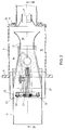
- Fig. 2 is a sectional view taken on line II-II of Fig. 3 of the burner;
- Fig. 3 is a sectional view taken on line III-III of Fig. 2 of the burner;
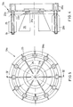
- Fig. 4 is a sectional view taken on line IV-IV of Fig. 5 of the burner ring and the burner plate;
- Fig. 5 is a side view of the burner ring and the burner plate taken on line V-V of Fig. 4;
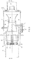
- Fig. 6 is a similar view as shown in Fig. 2 of another embodiment of the venturi burner; and
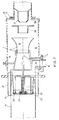
- Fig. 7 is a view similar to Fig. 3 of the exemplary embodiment shown in Fig. 6.
- Fig. 1 shows a boiler 1 with a
burner 3 connected to theboiler front 2, which burner comprises aburner housing 4 and anair supply fan 5. The boiler comprises afurnace 6, aheat exchanger 7 and aflue gas discharge 8. The burner housing 4 of theburner 3 is connected to an opening in theboiler front 2 by anoutlet end 9 and to the blow-out opening 11 of theair supply fan 5 by theinlet end 10. Theburner 3, shown in detail in Figs 2 and 3, comprises amixing tube 12, extending concentrically within theburner housing 4 and connecting to aburner head 13 at the outlet end of theburner housing 4. Theburner head 13 is surrounded by aflame cup 14. The burner head 13 and theflame cup 14 extend into thefurnace 6 of the boiler 1. Located between theburner housing 4 and themixing tube 12 is anannular space 15, being in open communication with thefurnace 6 at the outlet end and with theinner space 16 of themixing tube 12 at the inlet end of theburner housing 4. Via an axiallyadjustable injection nozzle 17, thefan 5 blows combustion air into theinner space 16 of themixing tube 12. The flow rate of the combustion air at the inlet of themixing tube 12 depends on the distance of theinjection nozzle 17 from the inlet of themixing tube 12. In the case of a greater distance, the combustion air must travel a greater distance before it reaches themixing tube 12 and, accordingly, has a lower flow rate at the inlet of themixing tube 12. Theinjection nozzle 17 being axially adjustable, thefan 5 need only be designed for rotation at a fixed speed. The fuel is supplied via thefuel connection 18 and passed to theburner head 13 via afuel channel 19. - The
mixing tube 12 is designed as a venturi. As the combustion air coming from thefan 5 is compressed in the venturi and, after the throat, expanded over a particular distance, an underpressure is produced at the venturi inlet which is proportional to the combustion air flow rate. Due to the underpressure and the overpressure prevailing in thefurnace 6, a portion of the flue gas is conducted via the annular space from thefurnace 6 to the inlet of themixing tube 12. Mixture of the combustion air with flue gas reduces the partial oxygen pressure of the combustion air, so that the heat capacity of the flue gas is increased and, accordingly, the flame temperature is reduced, so that the NOx emission is reduced. As the underpressure in themixing tube 12 is substantially proportional to the combustion air flow rate, the amount of flue gas that is recirculated will decrease proportionally to the combustion air flow rate even when theburner 3 is modulated. - Figs 6 and 7 show an alternative exemplary embodiment of the burner according to the invention, wherein the parts with the same function as the parts of the exemplary embodiment shown in Figs 2 and 3 are designated by the same reference numerals. The alternative exemplary embodiment comprises an
intermediate ring 28, accommodated concentrically in the burner housing 4 downstream from theair injection nozzle 17 and upstream from themixing tube inlet 12, whichintermediate ring 28 comprises aflange 29. - Due to the presence of the
intermediate ring 28, combustion air supplied by means of thefan 5 is already mixed with flue gases before the combustion air reaches the mixingtube 12. Subsequently, due to the underpressure in theinner space 16 of theventuri 12, additional flue gas is drawn in and mixed with the combustion air. This enables operation with anair injector 17 having a larger cross-sectional area than is conventional, so that the resistance experienced by the combustion air is lower and the engine power of thefan 5 can be chosen to be low. Consequently, theintermediate ring 28 enables sufficient flue gases to be drawn in, even at a lower combustion air rate in theventuri 12. - Optionally, the
flange 29, extending perpendicularly to the burner housing center line in the exempary embodiment shown, may be funnel-shaped, the wide mouth of the funnel being directed to theinjection nozzle 17. Such design of theflange 29 reduces the chance of combustion air, injected viaair injector 17, being blown directly into the boiler furnace via theannular space 15 round theventuri 12. - The
burner head 13 comprises two concentric burner rings 20, 21, the inner ring being designed as aburner plate 21. The flue gas/combustion air mixture flows round theburner ring 20 and theburner plate 21 in axial direction, i.e. in the direction of the burner axis. Theburner ring 20 and theburner plate 21 comprise radial combustionmedium outlet openings 22 which are directed radially, i.e. perpendicularly to the burner axis. Arranged upstream from these outlet openings areradial projections 23 promoting the fuel/air mixture by causing a vortex in the combustion air. Such burner head provides a stable flame front. - For the further reduction of the NOx emission, an
alternative burner head 13a is proposed, shown in detail in Figs 4 and 5. Theburner head 13a is designed for two-stage combustion in that, in addition to thefuel outlet openings 22a of the or eachburner ring 20a, a second series offuel outlet openings 24 is arranged downstream therefrom. In the exemplary embodiment shown in Figs 4 and 5, this is realized through the arrangement oftubes 25, directed axially downstream, on theouter burner ring 20a, whichtubes 25 are closed at the outer ends thereof and which comprise radially directedoutlet openings 24. Also, upstream from thegas outlet openings 24 of the second combustion zone, radial projections are provided for obtaining a proper mixture, created by vortex, between the outflowing gas and the combustion air. In this exemplary embodiment, the flow-through surface of the first series ofoutlet openings 22a is 25% and the flow-through area of the second series ofoutlet openings 24 is 75% of the total flow-through area. As only 25% of the total amount of fuel is released at the first series of outlet openings and is combusted at that location, an excess of air is present at that location. The relatively large amount of air can take up the heat of the flames at the hollow rings. At the second series of fuel outlet openings, the combustion air is consumed entirely. As the second, downstream combustion zone is located in the vicinity of the open end of theflame cup 14, the heat developed at that location can be delivered directly to thefurnace 6. In total, this yields a significant reduction of the flame temperature and, accordingly, a reduction of the NOx emission. - In addition, the
burner plate 21a and thetubes 25 comprise plate-shapedelements - With a gas burner provided with a mixing
tube 12, designed as a venturi, and a two-stage combustion head 13a, a reduction of the NOx emission of approx. 75% is realized. - To improve the conduction of the flue gas from the
furnace 6 to theannular space 15 between the mixingtube 12 and theburner housing 4, theburner housing 4, at the outlet side thereof, has been extended to include aflame cup 27, exending into thefurnace 6 and surrounding mixingtube 12 at a radial distance. - It will be understood that the invention is not limited to the exemplary embodiment described, but that various modifications are possible within the scope of the invention.
Claims (9)
- A burner, in particular a gas-fired fan burner for a central heating installation, comprising a substantially cylindrical burner housing, of which one end, being the outlet end, is connectable to an opening in a furnace wall of a central heating boiler, while to the other end thereof, being the inlet end of the burner housing, a burner fan for forced supply of combustion air and a fuel supply line are connectable, a mixing tube extending concentrically within the burner housing and connecting to a burner head at the outlet end of the burner housing, said burner head, in mounted condition of the burner, extending into the furnace by a flame cup surrounding the burner head, while an annular space between the burner housing wall and the mixing tube is in open communication with the furnace at the outlet end and with the inner space of the mixing tube at the inlet end of the burner housing, characterized in that the inner side of the mixing tube (12) in the burner housing (4) is designed as a venturi.
- A burner according to claim 1, characterized in that in the blow-out opening (11) of the burner fan (5) an air injection nozzle (17) is provided, which is constricted relative to the cross-sectional area of the blow-out opening (11).
- A burner according to claim 2, characterized in that the air injection nozzle (17) is axially adjustable.
- A burner according to claim 2 or 3, characterized by an intermediate ring (28), accommodated concentrically in the burner housing (4), downstream from the air injection nozzle (17) and upstream from the mixing tube inlet (12), provided with a flange (29).
- A burner according to any one of the preceding claims, characterized in that the burner head (13a) is adapted for two-stage combustion through providing, in addition to a first series of gas outlet openings (22a), a second series of gas outlet openings (24) downstream from the first series.
- A burner according to claim 5, characterized in that the gas outlet openings (22a, 24) are adjusted such that at the first series approx. 25% and at the second series approx. 75% of the gas flows out.
- A burner according to claim 5 or 6, characterized in that the burner head (13a) comprises one or several concentric, hollow gas-conducting rings (20a, 21a), each ring having gas outlet openings (22a) perpendicular to the burner axis and distributed in circumferential direction, said openings forming the first series of gas outlet openings (22a), and flange-shaped radial projections provided upstream from the gas outlet openings (22a), one or a plurality of the gas-conducting rings (20a) being provided with tubes (25), directed downstream, whose ends are closed off, said tubes (25), in the vicinity of the closed ends thereof, comprising gas outlet openings (24) in a plane perpendicular to the burner axis, forming the second series of gas outlet openings.
- A burner according to claim 7, characterized in that the tubes (25) and/or gas-conducting rings (20a, 21a) are provided with axial, plate-shaped elements (26, 26a) enlarging the heated surface.
- A burner according to any one of the preceding claims, characterized in that the burner housing (4) at the outlet end thereof is extended by an outer flame cup (27), said outer flame cup (27), when the burner (3) is in mounted condition, extending into the furnace (6) and surrounding the mixing tube (12) at a radial distance.
Applications Claiming Priority (4)
| Application Number | Priority Date | Filing Date | Title |
|---|---|---|---|
| NL9300335A NL9300335A (en) | 1993-02-23 | 1993-02-23 | Venturi burner |
| NL9300335 | 1993-02-23 | ||
| NL9301757A NL9301757A (en) | 1993-10-11 | 1993-10-11 | Venturi burner |
| NL9301757 | 1993-10-11 |
Publications (1)
| Publication Number | Publication Date |
|---|---|
| EP0612959A1 true EP0612959A1 (en) | 1994-08-31 |
Family
ID=26647072
Family Applications (1)
| Application Number | Title | Priority Date | Filing Date |
|---|---|---|---|
| EP94200429A Withdrawn EP0612959A1 (en) | 1993-02-23 | 1994-02-21 | Venturi burner |
Country Status (1)
| Country | Link |
|---|---|
| EP (1) | EP0612959A1 (en) |
Cited By (11)
| Publication number | Priority date | Publication date | Assignee | Title |
|---|---|---|---|---|
| NL1008233C2 (en) | 1998-02-06 | 1999-08-09 | Clysan D W Bv | Forced injection gas burner for boiler or furnace |
| EP1026445A1 (en) * | 1999-02-08 | 2000-08-09 | D.W. Clysan B.V. | Gas burner |
| FR2794521A1 (en) * | 1999-06-04 | 2000-12-08 | Geminox | Gas burner for boiler includes tubular structure for connection to fan, providing simplified forced ventilation assembly |
| KR100365652B1 (en) * | 2000-10-30 | 2002-12-26 | 주식회사 경동보일러 | Orifice Mixer For The Wind Fan Of Gas Boiler |
| FR2914398A1 (en) * | 2007-04-02 | 2008-10-03 | Pillard Chauffage | GASEOUS FUEL BURNER |
| EP2098782A1 (en) * | 2007-12-02 | 2009-09-09 | Beru Aktiengesellschaft | Device and method for operating flame ignition devices, exhaust gas purification devices of internal combustion engines (exhaust gas particulate filters) in particular for heavy goods vehicles, congeneration units or Stirling engines |
| CN105674269A (en) * | 2016-03-21 | 2016-06-15 | 浙江尚鼎工业炉有限公司 | Bent asymmetrical burner with Venturi tube |
| CN107559824A (en) * | 2016-06-30 | 2018-01-09 | 深圳市爱可机器人技术有限公司 | All-premixing burner and the cooking device for including it |
| EP3940293A1 (en) * | 2020-07-10 | 2022-01-19 | ELCO Burners GmbH | Method for staged combustion of a fuel and combustion head |
| EP4375571A3 (en) * | 2022-11-23 | 2024-06-12 | Beckett Thermal Solutions | Burner with integral mixer |
| EP4168712B1 (en) * | 2020-06-17 | 2024-08-07 | C.I.B. Unigas S.p.A. | Heat generation system with a burner having a gas turbine for producing a flame |
Citations (6)
| Publication number | Priority date | Publication date | Assignee | Title |
|---|---|---|---|---|
| US3741166A (en) * | 1972-02-10 | 1973-06-26 | F Bailey | Blue flame retention gun burners and heat exchanger systems |
| US4130388A (en) * | 1976-09-15 | 1978-12-19 | Flynn Burner Corporation | Non-contaminating fuel burner |
| JPS55107811A (en) * | 1979-02-14 | 1980-08-19 | Daido Steel Co Ltd | Radiant tube heating device |
| EP0347834A2 (en) * | 1988-06-21 | 1989-12-27 | Walter Dreizler | Burner head for a forced-draft gas burner |
| EP0378517A2 (en) * | 1989-01-09 | 1990-07-18 | Füllemann Patent Ag | Burner for the combustion of gaseous fuels and/or liquid fuels in the gaseous state |
| EP0433554A1 (en) * | 1989-11-23 | 1991-06-26 | Elco Energiesysteme Ag | Burner for the combustion or liquid or gaseous fuels |
-
1994
- 1994-02-21 EP EP94200429A patent/EP0612959A1/en not_active Withdrawn
Patent Citations (6)
| Publication number | Priority date | Publication date | Assignee | Title |
|---|---|---|---|---|
| US3741166A (en) * | 1972-02-10 | 1973-06-26 | F Bailey | Blue flame retention gun burners and heat exchanger systems |
| US4130388A (en) * | 1976-09-15 | 1978-12-19 | Flynn Burner Corporation | Non-contaminating fuel burner |
| JPS55107811A (en) * | 1979-02-14 | 1980-08-19 | Daido Steel Co Ltd | Radiant tube heating device |
| EP0347834A2 (en) * | 1988-06-21 | 1989-12-27 | Walter Dreizler | Burner head for a forced-draft gas burner |
| EP0378517A2 (en) * | 1989-01-09 | 1990-07-18 | Füllemann Patent Ag | Burner for the combustion of gaseous fuels and/or liquid fuels in the gaseous state |
| EP0433554A1 (en) * | 1989-11-23 | 1991-06-26 | Elco Energiesysteme Ag | Burner for the combustion or liquid or gaseous fuels |
Non-Patent Citations (1)
| Title |
|---|
| PATENT ABSTRACTS OF JAPAN vol. 004, no. 158 (M - 039) 5 November 1980 (1980-11-05) * |
Cited By (13)
| Publication number | Priority date | Publication date | Assignee | Title |
|---|---|---|---|---|
| NL1008233C2 (en) | 1998-02-06 | 1999-08-09 | Clysan D W Bv | Forced injection gas burner for boiler or furnace |
| EP1026445A1 (en) * | 1999-02-08 | 2000-08-09 | D.W. Clysan B.V. | Gas burner |
| FR2794521A1 (en) * | 1999-06-04 | 2000-12-08 | Geminox | Gas burner for boiler includes tubular structure for connection to fan, providing simplified forced ventilation assembly |
| KR100365652B1 (en) * | 2000-10-30 | 2002-12-26 | 주식회사 경동보일러 | Orifice Mixer For The Wind Fan Of Gas Boiler |
| FR2914398A1 (en) * | 2007-04-02 | 2008-10-03 | Pillard Chauffage | GASEOUS FUEL BURNER |
| EP1980788A1 (en) * | 2007-04-02 | 2008-10-15 | Fives Pillard | Gaseous fuel burner |
| EP2098782A1 (en) * | 2007-12-02 | 2009-09-09 | Beru Aktiengesellschaft | Device and method for operating flame ignition devices, exhaust gas purification devices of internal combustion engines (exhaust gas particulate filters) in particular for heavy goods vehicles, congeneration units or Stirling engines |
| CN105674269A (en) * | 2016-03-21 | 2016-06-15 | 浙江尚鼎工业炉有限公司 | Bent asymmetrical burner with Venturi tube |
| CN105674269B (en) * | 2016-03-21 | 2017-12-01 | 长兴金诺机械有限公司 | A kind of curved shape asymmetric burner with Venturi tube |
| CN107559824A (en) * | 2016-06-30 | 2018-01-09 | 深圳市爱可机器人技术有限公司 | All-premixing burner and the cooking device for including it |
| EP4168712B1 (en) * | 2020-06-17 | 2024-08-07 | C.I.B. Unigas S.p.A. | Heat generation system with a burner having a gas turbine for producing a flame |
| EP3940293A1 (en) * | 2020-07-10 | 2022-01-19 | ELCO Burners GmbH | Method for staged combustion of a fuel and combustion head |
| EP4375571A3 (en) * | 2022-11-23 | 2024-06-12 | Beckett Thermal Solutions | Burner with integral mixer |
Similar Documents
| Publication | Publication Date | Title |
|---|---|---|
| US9822967B2 (en) | Apparatus for burning pulverized solid fuels with oxygen | |
| KR910006234B1 (en) | Apparatus for coal combustion | |
| US5603906A (en) | Low NOx burner | |
| US4748919A (en) | Low nox multi-fuel burner | |
| US4930430A (en) | Burners | |
| JP2868515B2 (en) | Combustion chamber system for gas turbine | |
| KR100472900B1 (en) | An Improved Pulverized Coal Burner | |
| US4488869A (en) | High efficiency, low NOX emitting, staged combustion burner | |
| CA2226809C (en) | Flare apparatus and methods | |
| JP3404981B2 (en) | Gas heating device | |
| US20030233833A1 (en) | Pressure ram device on a gas turbine combustor | |
| US5791892A (en) | Premix burner | |
| EP0612959A1 (en) | Venturi burner | |
| US5975887A (en) | Compact hi-spin gas burner assembly | |
| JP2001510885A (en) | Burner device for combustion equipment, especially for gas turbine combustors | |
| US4115050A (en) | Burner construction and method for burning liquid and/or gaseous fuel | |
| US6050809A (en) | Immersion tube burner with improved flame stability | |
| US3529917A (en) | Air-mixing device for fuel burner | |
| US6029647A (en) | Recuperative radiant tube with hot side vitiation | |
| US6145450A (en) | Burner assembly with air stabilizer vane | |
| US5666944A (en) | Water heating apparatus with passive flue gas recirculation | |
| US4979894A (en) | Arrangement for burning fuels in a narrow combustion space | |
| JPS5827216Y2 (en) | burner assembly | |
| US5857846A (en) | Burner | |
| US5934898A (en) | Burner nozzle with improved flame stability |
Legal Events
| Date | Code | Title | Description |
|---|---|---|---|
| PUAI | Public reference made under article 153(3) epc to a published international application that has entered the european phase |
Free format text: ORIGINAL CODE: 0009012 |
|
| AK | Designated contracting states |
Kind code of ref document: A1 Designated state(s): AT BE CH DE DK ES FR GB IT LI LU NL SE |
|
| STAA | Information on the status of an ep patent application or granted ep patent |
Free format text: STATUS: THE APPLICATION IS DEEMED TO BE WITHDRAWN |
|
| 18D | Application deemed to be withdrawn |
Effective date: 19950301 |