EP0347783A2 - Procédé et dispositif pour produire des motifs au moyen de couleurs ou analogues sur des substrats - Google Patents
Procédé et dispositif pour produire des motifs au moyen de couleurs ou analogues sur des substrats Download PDFInfo
- Publication number
- EP0347783A2 EP0347783A2 EP89111030A EP89111030A EP0347783A2 EP 0347783 A2 EP0347783 A2 EP 0347783A2 EP 89111030 A EP89111030 A EP 89111030A EP 89111030 A EP89111030 A EP 89111030A EP 0347783 A2 EP0347783 A2 EP 0347783A2
- Authority
- EP
- European Patent Office
- Prior art keywords
- dye
- base
- guide
- dye carrier
- magnet
- Prior art date
- Legal status (The legal status is an assumption and is not a legal conclusion. Google has not performed a legal analysis and makes no representation as to the accuracy of the status listed.)
- Granted
Links
Images
Classifications
-
- B—PERFORMING OPERATIONS; TRANSPORTING
- B44—DECORATIVE ARTS
- B44C—PRODUCING DECORATIVE EFFECTS; MOSAICS; TARSIA WORK; PAPERHANGING
- B44C1/00—Processes, not specifically provided for elsewhere, for producing decorative surface effects
- B44C1/04—Producing precipitations
-
- B—PERFORMING OPERATIONS; TRANSPORTING
- B44—DECORATIVE ARTS
- B44C—PRODUCING DECORATIVE EFFECTS; MOSAICS; TARSIA WORK; PAPERHANGING
- B44C1/00—Processes, not specifically provided for elsewhere, for producing decorative surface effects
-
- B—PERFORMING OPERATIONS; TRANSPORTING
- B44—DECORATIVE ARTS
- B44D—PAINTING OR ARTISTIC DRAWING, NOT OTHERWISE PROVIDED FOR; PRESERVING PAINTINGS; SURFACE TREATMENT TO OBTAIN SPECIAL ARTISTIC SURFACE EFFECTS OR FINISHES
- B44D3/00—Accessories or implements for use in connection with painting or artistic drawing, not otherwise provided for; Methods or devices for colour determination, selection, or synthesis, e.g. use of colour tables
- B44D3/22—Implements or apparatus for special techniques, e.g. for painting lines, for pouring varnish; Batik pencils
Definitions
- the invention relates to a method for producing patterns by means of paint or the like on documents, in particular from paper, cardboard, wood, ceramics, porcelain, glass and on textile documents; it also relates to a device with which the method can advantageously be carried out.
- the movement of dye carriers which contain at least ferromagnetic parts, in the field of guide magnets is used according to the invention.
- dye carriers of this type with ferromagnetic properties moved by the guide magnetic field, are moved on the substrate, whereby they release previously absorbed dyes onto the substrate and thus leave their traces.
- the dye carriers are dragged along by the movement of the magnet and leave corresponding traces on the documents.
- the base is covered with a filler or a color spatula
- the moving dye carriers create structures in the spatula and thus produce the desired pattern.
- the resulting pattern is largely determined by the movement of the guide magnets, which can be done manually or via electro-mechanical drive elements.
- DE-0S 20 10 831 discloses the generation of patterns in color applications in that the applied color contains ferromagnetic particles which are arranged in the field of a magnet. Here, however, the particles are present in the color to be applied and lead from the start ben in this. In contrast, the dye carriers used here with ferromagnetic properties are always much thicker than the thickness of the resulting paint application for paint applications and at least as thick as the thickness of the spatula application for spatulas and they do not remain on the base after the sample has been produced. With the method described in the cited publication, patterns dependent on the field of the magnet can be generated, while the field of the guide magnet is merely a means for moving the dye carriers with ferromagnetic properties.
- a dye carrier on a base with ferromagnetic properties is captured by the field of a guide magnet, the dye carrier is dragged along with the movement of the guide magnet and, if it is soaked with dye, leaves traces of dye on the base.
- Almost unrollable dyestuff carriers cannot follow the movement of the guide magnet without delay, since they experience inhibitions on the base as only almost unrollable bodies and have to "jump" over edges that prevent them from unrolling from time to time. This creates randomness in the traces of color left behind, which cause the pattern to be irregular.
- the pad is moved, for. B. rotated in the case of round documents or moved in the longitudinal direction of the web in the case of sheet-like documents, the movement advantageously takes place approximately transversely to the direction of movement (it being possible for round objects to move over the entire diameter).
- the guiding magnet is arranged under the base or above it.
- the dye carrier with ferromagnetic properties is drawn against the base by the magnetic field of the guide magnet, so that the magnetic field also takes on the pressing function in addition to the guide task.
- the dye carrier with ferromagnetic properties would be lifted from the magnetic field from the base, so that the arrangement would be ineffective. This is prevented in this case that the dye carrier remains "trapped" between the base and a plate arranged above the dye carrier and parallel to the base, the plate parallel to the base being designed such that it weakens the field of the guide magnet only insignificantly.
- the dye carrier with ferromagnetic properties can be realized in many ways: For the application of paint, ferromagnetic balls or rollers or even irregular bodies can be used directly. Are these z. B. porous made of sintered material, they have their own storage capacity for the dye. Another possibility is to provide these ferromagnetic bodies with a rubber or a plastic coating, which acts as a dye carrier. Finally, such dye supports can also be formed from steel wool, which is shaped into a kind of roller shape or into a kind of ball and has the "out-of-roundness" necessary to prevent smooth unrolling. Other possibilities exist in that ferromagnetic wire - preferably soft iron wire - is "crumpled up" to form a dye carrier.
- the wire is wrapped, covered or flocked for better ink absorption, preferably cotton yarns or fibers are used.
- an absorbent insert e.g. B. made of wool. Because of their porosity, such dye supports can also absorb appropriate amounts of dye, so that they leave sufficiently long traces of color on the base. It goes without saying that it is not only possible to use dyes for producing the patterns, but rather solvents which have been applied to this, solvents which have been applied, layers which have been removed, etching agents which change color or change the surface or with regard to batik Techniques also wax applications for the preparation of bath coloring or glue - the glue traces can be z. B. bring the desired color by sprinkling with color powder - dye orders are within the meaning of the invention.
- the pole shoes of the guide magnets are adapted to the shape of the dye carrier, so that an elongated air gap arises in the case of roller-shaped dye carriers, which is reduced to below the ball diameter in the case of spherical dye carriers.
- the movement of the guide magnet expediently takes place in a guide rail, so that this movement can be automated.
- the feed can also be randomly controlled via a corresponding random number generator, it being immaterial whether the feed takes place via double-acting hydraulic cylinders or electric servomotors or the like.
- Another way of realizing a multi-pole guide magnet for detecting several dye carriers is to arrange permanent magnets or electrically excited magnets in the form of a rod in such a way that the individual magnets lie against one another with the opposite pole direction, a separating plate made of non-ferromagnetic material advantageously being interposed.
- This can be done in a simple manner in that the magnets are designed as ring magnets which are pushed onto a shaft made of non-ferromagnetic material with mutually opposite magnetization directions, possibly with the non-ferromagnetic intermediate layers being interposed.
- This magnetic roller can be parallel to its longitudinal axis and perpendicular to it, e.g. B. be moved by a coordinate drive, it can also rotate and move the dye carrier via entrainment effects and bring them to rotation with a suitable configuration.
- the distance can be reduced to change the strength of the magnetic guide field for the dye carrier. This varies the pressure force and thus the strength of the color trace. It is conceivable that the leadership rail the movement of the guide magnet is provided with height adjustment devices. Permanent magnets can be used as guide magnets, which have the advantage that they do not need their own power supply. If electromagnets are used, the change in height of the guide magnet to vary the magnetic guide field for the dye carrier can be replaced by changing the current strength and thus the pole strength of the electromagnet.
- dye supplementation is given by the fact that the dye supply is provided in a container which can drip through a capillary. It goes without saying that this "dripping" can also take place in a form in the manner of an "injection syringe", the form advantageously being applied only when the dye carrier is in the receiving position. With the help of a guide magnet (or, if necessary, an auxiliary magnet), the dye carrier is brought under the drip-off opening of the capillary or under the tip of the needle, raised if necessary, and then takes over a measurable dose of color there.
- the dripping is replaced by a touch transfer, which is of particular interest if the dye carrier is designed to be rollable. If there is a plate arranged above the base and parallel to it and the dye carrier (s) are in the space between these two plates, the plate opposite the base can be coated with the dye in the form of e.g. B. a thin felt. In this case, the ink is transferred by rolling off the rollable dye carrier.
- color transfer namely the transfer of color powder (which can also be in the form of a compact powder) or of colored paste or colored liquid, in particular if this is used to impregnate a pillow, for example a stamp pad.
- another transfer means can also be used instead of the guide magnet, making it possible to grasp the dye carrier with the aid of a suction nozzle and to move it specifically to the location of the dye absorption.
- an auxiliary magnet that is independent of the guide magnet can also be used. It is expedient if the transfer means are moved parallel and synchronously with the guide magnet. Then these agents "find" the dye carrier assigned to them and, after picking up the color, can place it back in the field of the guide magnet.
- the dye application is carried out with several dye carriers, each dye carrier being assigned to a guide magnet and the guide magnets being movable essentially independently of one another.
- the transfer means - regardless of whether magnetic or absorbent - can be provided like a blanket over the entire ink application area.
- the forces exerted on the dye carriers by the transfer means must be greater than the forces exerted by the guide magnets on the dye carriers.
- the procedure can be such that the guide magnets are removed from the base when the color Material carriers for dye absorption are recorded with the transfer means and brought to the place of the color addition. The resulting increase in distance reduces the magnetic forces acting on the dye carrier. This procedure is particularly indicated when the guide magnets are permanent magnets.
- electromagnets are used as guide magnets, magnetic forces can also be reduced by reducing the current strengths which excite the electromagnet.
- different excitation of the electromagnets serving as guide magnets influences the pressure of the dye carrier on the base and thus the intensity of the application of paint. Different excitations can have additional effects.
- the base can also be provided with stocks of at least one, but advantageously several, dyes, for the reception of which channels or cups are arranged.
- the dyes can be liquid or powder, but can also be in the form of a paste.
- Dye-receiving cushions in the manner of stamp pads can also be arranged in the grooves or the cups, which ensure that the dye is distributed on the surface and prevent the porous part of the dye carrier from being soaked.
- the dye carrier With the help of its guide magnet, the dye carrier is brought to the dye reservoir from time to time and pressed onto or in the dye reservoir - for example by increasing the magnetic field (approximation, increasing the current) Document moves.
- auxiliary magnet so that the auxiliary magnet takes over the guidance of the dye carrier while it is being provided with new dye.
- the auxiliary magnet is more appropriate mechanically coupled with the guide magnet so that both are moved parallel to each other. If the dye carrier is to be provided with a new color, it is released by the auxiliary magnet, which is then excited, taken over by the guide magnet which is no longer excited. The auxiliary magnet now moves the dye carrier, lifted from the base to the dye supply.
- field configurations can be created in which the dye supports with ferromagnetic properties have a stable position in the vicinity of one of the poles. If the field distribution is changed by changing the excitation - provided electromagnets - or by changing the geometry when tilting the magnet arrangement - provided permanent or electromagnets - this position of the dye carrier loses stability and the dye carrier "jumps" into a new stable position. In this way, multi-pole-like fields as well as fields with the same polarity can be simulated with a field distribution dependent on the number of poles and the pole shape, each of which brings about different forms of movement in accordance with the interaction with the dye carrier with ferromagnetic properties.
- patterns created by hand can also be reproduced by z. B. with a mouse or a scanner and digitized stored in the memory of a computer.
- these stored patterns which can be changed in the computer itself by changing the scale, upsetting in one direction or the other, or the like, in Type of CAM control, the guide magnets are moved, so that this method can also be reproduced. It should be noted that the movement the dye carrier never follows the movement of the guide magnet exactly, so that the individual patterns obtained by this duplication show deviations from one another.
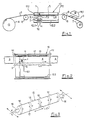
- the dye carrier 1 is captured by the magnetic field of the guide magnet 2, the magnetic field being essentially determined by the geometric shape of the pole pieces 3.1 and 3.2.
- the guide magnet 2 is arranged on a carriage 12; this carriage 12 is in turn movably attached to a rail 12.1 which extends transversely to the direction of movement of the base 5 to be provided with the pattern. If this magnet 2 is designed as an electromagnet, the legs of the pole shoes 3.1 and 3.2 or, as shown in FIG. 1, the yoke between them are provided with the excitation coil 4.
- the rail 12.1 is in turn placed on lateral guide webs 12.2, so that here too a movement can take place parallel to the direction of movement of the support 5.
- These side support rails 12.2 are provided with end stops to limit the path of the guide rail 12.1.
- the lateral support rails 12.2 are expediently fastened to the guide frame 10 for the base 5.
- This guide frame 10 consists of a support plate 11 and a frame 11.1 surrounding the paint application area, which in the area of the passage of the web-shaped Base 5 is set back with respect to the support plate, so that a slot for carrying out the base 5 is created.
- the base 5 itself - shown here as a paper web or textile web - is drawn off from a supply roll 6 and runs in particular to compensate for the changing diameter of the supply roll via a first deflection roller 8 into the guide frame 10.
- Above the support plate 11 is the ink application area, in which at least one dye carrier 1 - usually several with several guide magnets - is located.
- the continuous pattern of the sheet-like base 5, in cooperation with the movement of the guide magnet 2, creates the desired pattern; the patterned sheet-like base 5 runs out of the guide frame and is guided via a second deflection roller 8 into a drying section 9, in which, for. B. the applied colors can be dried by means of an IR radiator 9.1. After drying, the finished sheet-like base 5 is wound onto the supply roll 7.
- the second deflection roller 8 also ensures the clean discharge of the patterned sheet-like support 5 from the guide frame 10 despite the changing diameter of the winding roller 7. Care is also taken here with conventional means to ensure that auxiliary means such.
- B. IR radiator 9.1 keep a constant distance to the base 5 in the area of the drying section.
- Figure 2 shows a plan view, which is partially cut away.
- the dye supply in addition to liquid paint, powdered color pigments or pads soaked in the manner of ink pads can also be present in the channels 13, and the channels themselves can also be cup-shaped or similar
- the dye supply especially if it is a dye supply in the form of a compact powder or in the form of soaked pillows, can also be provided on the inside of the frame-like side walls 11.1 of the guide frame 10.
- FIG. 2 also shows the guide rail 12.1 lying on the lateral support rails 12.2 and extending transversely to the direction of movement of the web-shaped base 5, which is the guide for the sliding carriage 12 carrying the magnet 2.
- the drives for the movements themselves are conventional stepper motors, hydraulic or pneumatic cylinders or the like, which are switched randomly to generate repeatless patterns, so that the dye carrier 1 carries out random movements. It goes without saying that other types of controls are also possible, so that patterns with a greater or lesser degree of symmetry can also be formed. By controlling color supplies of different colors, color effects can also be created that lie in the color transition from one color to the other via appropriate mixing levels.
- the dye carrier does not have to be uniformly impregnated with a color, but can have areas in itself in which the one and other areas in which the other color is pure; in between there are areas with more or less thorough mixing of both colors. The same applies if three or more colors are used. During the irregular movement, the dye carrier is also rotated, so that the patterns held in the aforementioned color gradations are created.
- FIG. 3 shows a magnetic roller 15 with an annular permanent magnet as an example of a guide magnet 16.
- These permanent magnets are separated from one another by non-ferromagnetic (for example brass or aluminum) intermediate disks 17.
- the entire arrangement is located on a shaft 18.
- the shaft 18 can be moved with drives (not shown) according to the directions of the arrows: on the one hand, a movement in the axial direction is possible, this movement being generally limited to the length of a ring magnet, the Furthermore, a movement perpendicular to the axis is possible, this movement being to take place over the entire length of the base. Closing - rotation is possible, so that if the magnets and the ferromagnetic parts of the dyestuffs are suitably designed, they can be forced to rotate.
Landscapes
- Treatment Of Fiber Materials (AREA)
- Printing Methods (AREA)
- Application Of Or Painting With Fluid Materials (AREA)
Applications Claiming Priority (2)
| Application Number | Priority Date | Filing Date | Title |
|---|---|---|---|
| DE3820709A DE3820709A1 (de) | 1988-06-18 | 1988-06-18 | Verfahren und vorrichtung zum erzeugen von farbmustern auf unterlagen |
| DE3820709 | 1988-06-18 |
Publications (3)
| Publication Number | Publication Date |
|---|---|
| EP0347783A2 true EP0347783A2 (fr) | 1989-12-27 |
| EP0347783A3 EP0347783A3 (fr) | 1991-01-30 |
| EP0347783B1 EP0347783B1 (fr) | 1994-12-28 |
Family
ID=6356797
Family Applications (1)
| Application Number | Title | Priority Date | Filing Date |
|---|---|---|---|
| EP89111030A Expired - Lifetime EP0347783B1 (fr) | 1988-06-18 | 1989-06-17 | Procédé et dispositif pour produire des motifs au moyen de couleurs ou analogues sur des substrats |
Country Status (3)
| Country | Link |
|---|---|
| EP (1) | EP0347783B1 (fr) |
| DE (2) | DE3820709A1 (fr) |
| ES (1) | ES2068850T3 (fr) |
Cited By (2)
| Publication number | Priority date | Publication date | Assignee | Title |
|---|---|---|---|---|
| EP2189286A3 (fr) * | 2003-06-30 | 2010-08-04 | Kba-Giori S.A. | Machine et procédé d'impression |
| CN116641243A (zh) * | 2023-01-30 | 2023-08-25 | 宣城凯欧纺织有限公司 | 一种点缀式特硬油亮仿蜡面料的加工方法 |
Family Cites Families (2)
| Publication number | Priority date | Publication date | Assignee | Title |
|---|---|---|---|---|
| US2584021A (en) * | 1949-06-28 | 1952-01-29 | Jackson Louis | Apparatus for producing artistic designs in absorbent material |
| IT938725B (it) * | 1970-11-07 | 1973-02-10 | Magnetfab Bonn Gmbh | Procedimento e dispositivo per otte nere disegni in strati superficiali per mezzo di campi magnetici |
-
1988
- 1988-06-18 DE DE3820709A patent/DE3820709A1/de not_active Withdrawn
-
1989
- 1989-06-17 EP EP89111030A patent/EP0347783B1/fr not_active Expired - Lifetime
- 1989-06-17 ES ES89111030T patent/ES2068850T3/es not_active Expired - Lifetime
- 1989-06-17 DE DE58908818T patent/DE58908818D1/de not_active Expired - Fee Related
Cited By (2)
| Publication number | Priority date | Publication date | Assignee | Title |
|---|---|---|---|---|
| EP2189286A3 (fr) * | 2003-06-30 | 2010-08-04 | Kba-Giori S.A. | Machine et procédé d'impression |
| CN116641243A (zh) * | 2023-01-30 | 2023-08-25 | 宣城凯欧纺织有限公司 | 一种点缀式特硬油亮仿蜡面料的加工方法 |
Also Published As
| Publication number | Publication date |
|---|---|
| ES2068850T3 (es) | 1995-05-01 |
| DE3820709A1 (de) | 1989-12-21 |
| DE58908818D1 (de) | 1995-02-09 |
| EP0347783A3 (fr) | 1991-01-30 |
| EP0347783B1 (fr) | 1994-12-28 |
Similar Documents
| Publication | Publication Date | Title |
|---|---|---|
| DE4227136C2 (de) | Verfahren und Vorrichtung zum Befeuchten einer bedruckten und anschließend thermisch getrockneten, bewegten Materialbahn, insbesondere Papierbahn | |
| DE2156154C3 (de) | Verfahren und Vorrichtung zum Bedrucken eines luftdurchlässigen flächenhaften Körpers | |
| DE7622143U1 (de) | Vorrichtung zum aufbringen von mustern auf eine warenbahn | |
| DE3210551A1 (de) | Verfahren und vorrichtung zum anbringen eines praegefolien-abdruckes auf einer flexiblen materialbahn | |
| DE1164233B (de) | Vorrichtung zur Erzeugung eines Pressdruckes auf bahnenfoermige Materialien | |
| DE3427306C2 (de) | Plotter | |
| DE2831797A1 (de) | Verfahren zur magnetofluiden aufzeichnung | |
| DE1253941B (de) | Schnelldruckvorrichtung | |
| EP0347783B1 (fr) | Procédé et dispositif pour produire des motifs au moyen de couleurs ou analogues sur des substrats | |
| EP0264396B1 (fr) | Dispositif pour appliquer de faibles ou tres faibles quantites de substances coulantes | |
| DE4213013C2 (de) | Vorrichtung zum Erzeugen eines zu druckenden Musters auf einer Druckform-Hülse | |
| EP0681526B1 (fr) | Procede d'impression avec un tampon | |
| WO1993004862A1 (fr) | Machine a imprimer a tampon | |
| DE1183104B (de) | Speichergesteuertes ferromagnetisches Druckwerk | |
| DE2608005C3 (de) | Verfahren und Vorrichtung zum Bemustern oder Färben von flächigem Textilgut o.dgl | |
| DE60005455T2 (de) | Rakelgerät | |
| DE4315261C2 (de) | Verfahren und Vorrichtung zur Herstellung eines Wabenkörpers | |
| DE538998C (de) | Vorrichtung zum Einschraenken von Registerungenauigkeiten bei Mehrfarben-Rotations-Tiefdruckmaschinen | |
| DE2136091C3 (de) | Rotationsschablonendruckvorrichtung für Sieb- und Filmdruck | |
| DE551089C (de) | Bedrucken von Stoffbahnen | |
| DE3117947A1 (de) | Flachsiebdruckvorrichtung | |
| DE643683C (de) | Verfahren und Vorrichtung zum Herstellen von Stoffen mit schleifendem UEberzug | |
| DE2531506A1 (de) | Kalander zur fortlaufenden behandlung einer warenbahn aus papier, textil oder kunststoff durch mittels magnetkraft erzeugten druck | |
| DE1671549C (de) | Verfahren zum dauerhaften Verbinden feinkörniger Magnetteilchen mit der Oberfläche einer porösen Unterlage aus nichtmagnetischem Material, insbesondere Papier oder dgl. Ausscheidung aus: 1522642 | |
| EP0769375B1 (fr) | Machine rotative de sérigraphie |
Legal Events
| Date | Code | Title | Description |
|---|---|---|---|
| PUAI | Public reference made under article 153(3) epc to a published international application that has entered the european phase |
Free format text: ORIGINAL CODE: 0009012 |
|
| AK | Designated contracting states |
Kind code of ref document: A2 Designated state(s): DE ES FR GB IT NL SE |
|
| PUAL | Search report despatched |
Free format text: ORIGINAL CODE: 0009013 |
|
| AK | Designated contracting states |
Kind code of ref document: A3 Designated state(s): DE ES FR GB IT NL SE |
|
| 17P | Request for examination filed |
Effective date: 19910726 |
|
| 17Q | First examination report despatched |
Effective date: 19930324 |
|
| RAP3 | Party data changed (applicant data changed or rights of an application transferred) |
Owner name: STEINER, MICHAEL |
|
| GRAA | (expected) grant |
Free format text: ORIGINAL CODE: 0009210 |
|
| AK | Designated contracting states |
Kind code of ref document: B1 Designated state(s): DE ES FR GB IT NL SE |
|
| PG25 | Lapsed in a contracting state [announced via postgrant information from national office to epo] |
Ref country code: IT Free format text: LAPSE BECAUSE OF FAILURE TO SUBMIT A TRANSLATION OF THE DESCRIPTION OR TO PAY THE FEE WITHIN THE PRESCRIBED TIME-LIMIT;WARNING: LAPSES OF ITALIAN PATENTS WITH EFFECTIVE DATE BEFORE 2007 MAY HAVE OCCURRED AT ANY TIME BEFORE 2007. THE CORRECT EFFECTIVE DATE MAY BE DIFFERENT FROM THE ONE RECORDED. Effective date: 19941228 Ref country code: NL Effective date: 19941228 |
|
| REF | Corresponds to: |
Ref document number: 58908818 Country of ref document: DE Date of ref document: 19950209 |
|
| PG25 | Lapsed in a contracting state [announced via postgrant information from national office to epo] |
Ref country code: SE Effective date: 19950328 |
|
| ET | Fr: translation filed | ||
| REG | Reference to a national code |
Ref country code: ES Ref legal event code: FG2A Ref document number: 2068850 Country of ref document: ES Kind code of ref document: T3 |
|
| GBT | Gb: translation of ep patent filed (gb section 77(6)(a)/1977) |
Effective date: 19950404 |
|
| NLV1 | Nl: lapsed or annulled due to failure to fulfill the requirements of art. 29p and 29m of the patents act | ||
| PLBE | No opposition filed within time limit |
Free format text: ORIGINAL CODE: 0009261 |
|
| STAA | Information on the status of an ep patent application or granted ep patent |
Free format text: STATUS: NO OPPOSITION FILED WITHIN TIME LIMIT |
|
| 26N | No opposition filed | ||
| PGFP | Annual fee paid to national office [announced via postgrant information from national office to epo] |
Ref country code: ES Payment date: 19960628 Year of fee payment: 8 |
|
| PGFP | Annual fee paid to national office [announced via postgrant information from national office to epo] |
Ref country code: FR Payment date: 19970530 Year of fee payment: 9 |
|
| PGFP | Annual fee paid to national office [announced via postgrant information from national office to epo] |
Ref country code: GB Payment date: 19970613 Year of fee payment: 9 |
|
| PG25 | Lapsed in a contracting state [announced via postgrant information from national office to epo] |
Ref country code: ES Free format text: LAPSE BECAUSE OF NON-PAYMENT OF DUE FEES Effective date: 19970618 |
|
| PG25 | Lapsed in a contracting state [announced via postgrant information from national office to epo] |
Ref country code: GB Free format text: LAPSE BECAUSE OF NON-PAYMENT OF DUE FEES Effective date: 19980617 |
|
| GBPC | Gb: european patent ceased through non-payment of renewal fee |
Effective date: 19980617 |
|
| PG25 | Lapsed in a contracting state [announced via postgrant information from national office to epo] |
Ref country code: FR Free format text: LAPSE BECAUSE OF NON-PAYMENT OF DUE FEES Effective date: 19990226 |
|
| REG | Reference to a national code |
Ref country code: FR Ref legal event code: ST |
|
| REG | Reference to a national code |
Ref country code: ES Ref legal event code: FD2A Effective date: 20000403 |
|
| PGFP | Annual fee paid to national office [announced via postgrant information from national office to epo] |
Ref country code: DE Payment date: 20050615 Year of fee payment: 17 |
|
| PG25 | Lapsed in a contracting state [announced via postgrant information from national office to epo] |
Ref country code: DE Free format text: LAPSE BECAUSE OF NON-PAYMENT OF DUE FEES Effective date: 20070103 |