EP0347631A2 - Stichsäge mit Absaugung - Google Patents
Stichsäge mit Absaugung Download PDFInfo
- Publication number
- EP0347631A2 EP0347631A2 EP89110000A EP89110000A EP0347631A2 EP 0347631 A2 EP0347631 A2 EP 0347631A2 EP 89110000 A EP89110000 A EP 89110000A EP 89110000 A EP89110000 A EP 89110000A EP 0347631 A2 EP0347631 A2 EP 0347631A2
- Authority
- EP
- European Patent Office
- Prior art keywords
- suction
- base plate
- jigsaw
- housing
- shoe
- Prior art date
- Legal status (The legal status is an assumption and is not a legal conclusion. Google has not performed a legal analysis and makes no representation as to the accuracy of the status listed.)
- Granted
Links
Images

Classifications
-
- B—PERFORMING OPERATIONS; TRANSPORTING
- B23—MACHINE TOOLS; METAL-WORKING NOT OTHERWISE PROVIDED FOR
- B23Q—DETAILS, COMPONENTS, OR ACCESSORIES FOR MACHINE TOOLS, e.g. ARRANGEMENTS FOR COPYING OR CONTROLLING; MACHINE TOOLS IN GENERAL CHARACTERISED BY THE CONSTRUCTION OF PARTICULAR DETAILS OR COMPONENTS; COMBINATIONS OR ASSOCIATIONS OF METAL-WORKING MACHINES, NOT DIRECTED TO A PARTICULAR RESULT
- B23Q11/00—Accessories fitted to machine tools for keeping tools or parts of the machine in good working condition or for cooling work; Safety devices specially combined with or arranged in, or specially adapted for use in connection with, machine tools
- B23Q11/0042—Devices for removing chips
- B23Q11/0046—Devices for removing chips by sucking
-
- B—PERFORMING OPERATIONS; TRANSPORTING
- B23—MACHINE TOOLS; METAL-WORKING NOT OTHERWISE PROVIDED FOR
- B23D—PLANING; SLOTTING; SHEARING; BROACHING; SAWING; FILING; SCRAPING; LIKE OPERATIONS FOR WORKING METAL BY REMOVING MATERIAL, NOT OTHERWISE PROVIDED FOR
- B23D49/00—Machines or devices for sawing with straight reciprocating saw blades, e.g. hacksaws
- B23D49/10—Hand-held or hand-operated sawing devices with straight saw blades
- B23D49/16—Hand-held or hand-operated sawing devices with straight saw blades actuated by electric or magnetic power or prime movers
- B23D49/162—Pad sawing devices
- B23D49/167—Pad sawing devices with means to adjust the guide plate or with means to adjust the plane in which the saw blade moves
-
- B—PERFORMING OPERATIONS; TRANSPORTING
- B23—MACHINE TOOLS; METAL-WORKING NOT OTHERWISE PROVIDED FOR
- B23D—PLANING; SLOTTING; SHEARING; BROACHING; SAWING; FILING; SCRAPING; LIKE OPERATIONS FOR WORKING METAL BY REMOVING MATERIAL, NOT OTHERWISE PROVIDED FOR
- B23D51/00—Sawing machines or sawing devices working with straight blades, characterised only by constructional features of particular parts; Carrying or attaching means for tools, covered by this subclass, which are connected to a carrier at both ends
- B23D51/02—Sawing machines or sawing devices working with straight blades, characterised only by constructional features of particular parts; Carrying or attaching means for tools, covered by this subclass, which are connected to a carrier at both ends of beds; of guiding arrangements for work-tables or saw carriers; of frames
- B23D51/03—Sawing machines or sawing devices working with straight blades, characterised only by constructional features of particular parts; Carrying or attaching means for tools, covered by this subclass, which are connected to a carrier at both ends of beds; of guiding arrangements for work-tables or saw carriers; of frames with extensible or collapsible frames ; Frames with spare blade storage means
-
- B—PERFORMING OPERATIONS; TRANSPORTING
- B23—MACHINE TOOLS; METAL-WORKING NOT OTHERWISE PROVIDED FOR
- B23D—PLANING; SLOTTING; SHEARING; BROACHING; SAWING; FILING; SCRAPING; LIKE OPERATIONS FOR WORKING METAL BY REMOVING MATERIAL, NOT OTHERWISE PROVIDED FOR
- B23D59/00—Accessories specially designed for sawing machines or sawing devices
- B23D59/006—Accessories specially designed for sawing machines or sawing devices for removing or collecting chips
- B23D59/0064—Accessories specially designed for sawing machines or sawing devices for removing or collecting chips by suction
Definitions
- the invention relates to a jigsaw with suction according to the preamble of claim 1.
- a suction channel arranged above the base plate is provided for extracting the sawdust.
- the jigsaw blade is enclosed at the front by a one-piece cover hood connected to the housing, which extends to the base plate.
- a disadvantage of this known jigsaw is the need for the base plate to be replaced when sawing with suction. This is cumbersome and time-consuming, the one-piece cover hood does not allow the housing to be swiveled against the base plate to make bevel cuts. With the known design, only vertical saw cuts are possible.
- the object of the present invention is therefore to create a jigsaw of the type mentioned at the outset, which can be converted for suction and with which oblique saw cuts are also possible.
- suction device it is possible to convert jigsaws without suction in a simple manner by attaching the suction shoe from below to the base plate for work with suction.
- the suction shoe can advantageously be made of plastic, so there is the further advantage that the surface of the workpiece is protected when the jigsaw is placed on it.
- the jigsaw blade is enclosed at the front by a two-part cover, the two parts of which engage in one another in such a way that the housing can be pivoted in relation to the base plate in a known manner, so that oblique saw cuts with suction are also possible.
- suction shoe projects beyond the base plate to the rear, it can advantageously be provided with fastening elements into which jigsaw blades of various embodiments to be kept ready can be inserted.
- a jigsaw blade 3 that can be driven by an electric motor 2 is mounted in a housing 1 so that it can be moved back and forth.
- the housing 1 is arranged in a known manner on a base plate 4 such that it can be pivoted about a pivot axis 5 ⁇ 5 parallel to the feed direction in order to make oblique saw cuts. (See also Fig. 2).
- a suction shoe 6, which is made of plastic and whose elastic claws 7 grip around the base plate 4 from above, can be plugged onto the base plate 4 from below.
- the suction shoe 6 is designed as a flat frame, the outer walls 8 of which abut the base plate 4 on three sides.
- FIG. 3 shows, the suction shoe 6 open air duct 9 upward, which extend almost to the front edge 4 'of the base plate 4 and are opened against the jigsaw blade 3.
- the air guide channels 9 open into a suction nozzle 10 connected to the suction shoe 6, with which a hose (not shown) of the suction device can be connected.
- the jigsaw blade 3 is enclosed at the front by a two-part cover 11, the upper part 12 of which can be plugged onto the housing 1 with an elastic clip 13 and the lower part 14 of which can also be attached onto the base plate 4 with elastic clips 15.
- Upper part 12 and lower part 14 touch at their separation point with an arcuate outer contour 16 which is concentric to the pivot axis 5. This makes it possible to pivot the housing 1 against the base plate 4, the full suction power being retained.
- suction shoe 6 On the upward-facing surface of suction shoe 6, which protrudes beyond base plate 4, fastening elements 17 in the form of elastic clamps, in which jigsaw blades to be kept ready, can expediently be provided in addition to suction nozzle 10.
Landscapes
- Engineering & Computer Science (AREA)
- Mechanical Engineering (AREA)
- Sawing (AREA)
Abstract
Description
- Die Erfindung betrifft eine Stichsäge mit Absaugung gemäß Oberbegriff von Anspruch 1.
- Bei einer bekannten Stichsäge, die mit ihrer Grundplatte auf dem Werkstück aufsetzbar ist, ist zur Absaugung der Sägespäne ein oberhalb der Grundplatte angeordneter Absaugkanal vorgesehen. Das Stichsägeblatt ist nach vorne durch eine mit dem Gehäuse verbundene, einteilige Abdeckhaube umschlossen, die sich bis zur Grundplatte erstreckt.
- Nachteilig bei dieser bekannten Stichsäge ist die Notwendigkeit, daß bei Sägearbeiten mit Absaugung die Grundplatte ausgetauscht werden muß. Dies ist umständlich und zeitraubend, die einteilige Abdeckhaube erlaubt es dazuhin nicht, das Gehäuse gegen die Grundplatte zur Ausführung von Schrägschnitten zu schwenken. Mit der bekannten Ausführung sind also nur senkrechte Sägeschnitte möglich.
- Aufgabe der vorliegenden Erfindung ist daher die Schaffung einer Stichsäge der eingangs genannten Art,die für die Absaugung umgerüstet werden kann und mit der dabei auch schräge Sägeschnitte möglich sind.
- Diese Aufgabe wird erfindungsgemäß durch die im kennzeichnenden Teil des Anspruchs 1 angegebenen Merkmale gelöst.
- Bei der erfindungsgemäßen Absaugeinrichtung ist es möglich, Stichsägen ohne Absaugung auf einfache Art und Weise durch Aufstecken des Absaugschuhs von unten auf die Grundplatte für Arbeiten mit Absaugung umzurüsten.
- Der Absaugschuh kann vorteilhafterweise aus Kunststoff ausgeführt werden, damit ergibt sich der weitere Vorteil, daß die Oberfläche des Werkstücks beim Aufsetzen der Stichsäge geschont wird.
- Zur sicheren und wirkungsvollen Absaugung ist das Stichsägeblatt nach vorne durch eine zweiteilige Abdeckhaube umschlossen, deren beide Teile so ineinander eingreifen, daß sich das Gehäuse in bekannter Weise gegenüber der Grundplatte verschwenken läßt, so daß auch schräge Sägeschnitte mit Absaugung möglich sind.
- Da der Absaugschuh die Grundplatte nach hinten überragt, kann er vorteilhafterweise mit Befestigungselementen versehen sein, in die bereitzuhaltende Stichsägeblätter verschiedener Ausführungsformen einsteckbar sind.
- Im folgenden ist ein Ausführungsbeispiel der Erfindung unter Bezugnahme auf die Zeichnungen näher beschrieben:
- Es zeigen:
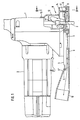
- Fig. 1 Stichsäge von der Seite, Absaugschuh und Abdeckhaube geschnitten
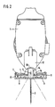
- Fig. 2 Schnitt nach Linie II - II in Fig. 1
- Fig. 3 Absaugschuh von oben
- Bei der in Fig. 1 gezeigten Stichsäge ist in einem Gehäuse 1 ein von einem Elektromotor 2 antreibbares Stichsägeblatt 3 hin- und her-verschiebbar gelagert. Das Gehäuse 1 ist in bekannter Weise auf einer Grundplatte 4 so angeordnet, daß es zur Ausführung von schrägen Sägeschnitten um eine zur Vorschubrichtung parallelen Schwenkachse 5⁻⁵schwenkbar ist. (Siehe auch Fig. 2).
- Zur Verbindung der Angriffstelle des Stichsägeblatts 3 mit einem nicht dargestellten Absauggerät läßt sich auf die Grundplatte 4 von unten ein Absaugschuh 6 aufstecken, der aus Kunststoff hergestellt ist und dessen elastische Pratzen 7 die Grundplatte 4 von oben umgreifen.
- Der Absaugschuh 6 ist als flacher Rahmen ausgeführt, dessen Außenwände 8 an drei Seiten an der Grundplatte 4 anliegen.
- Wie auch Fig. 3 zeigt, weist der Absaugschuh 6 nach oben offene Luftführungskanäle 9 auf, die sich nahezu bis zur Vorderkante 4′ der Grundplatte 4 erstrecken und gegen das Stichsägeblatt 3 geöffnet sind. Nach Hinterkante 4˝ von Grundplatte 4 münden die Luftführungskanäle 9 in einen mit dem Absaugschuh 6 verbundenen Absaugstutzen 10, mit dem ein nicht dargestellter Schlauch des Absauggeräts verbindbar ist.
- Das Stichsägeblatt 3 wird nach vorne von einer zweiteiligen Abdeckhaube 11 umschlossen, deren Oberteil 12 mit einer elastischen Klammer 13 auf das Gehäuse 1 und deren Unterteil 14 ebenfalls mit elastischen Klammern 15 auf die Grundplatte 4 aufsteckbar ist. Oberteil 12 und Unterteil 14 berühren sich an ihrer Trennstelle mit einer kreisbogenförmigen Außenkontur 16, die konzentrisch zur Schwenkachse 5 verläuft. Damit ist es möglich, das Gehäuse 1 gegen die Grundplatte 4 zu verschwenken, wobei die volle Absaugleistung erhalten bleibt.
- An der nach oben gerichteten Fläche von Absaugschuh 6, die die Grundplatte 4 nach hinten überragt, können neben dem Absaugstutzen 10 zweckmäßigerweise Befestigungselemente 17 in Form von elastischen Klammern vorgesehen sein, in denen sich bereitzuhaltende Stichsägeblätter unterbringen lassen.
Claims (4)
Applications Claiming Priority (2)
| Application Number | Priority Date | Filing Date | Title |
|---|---|---|---|
| DE3820752 | 1988-06-18 | ||
| DE3820752A DE3820752A1 (de) | 1988-06-18 | 1988-06-18 | Stichsaege mit absaugung |
Publications (3)
| Publication Number | Publication Date |
|---|---|
| EP0347631A2 true EP0347631A2 (de) | 1989-12-27 |
| EP0347631A3 EP0347631A3 (de) | 1991-02-06 |
| EP0347631B1 EP0347631B1 (de) | 1993-08-25 |
Family
ID=6356827
Family Applications (1)
| Application Number | Title | Priority Date | Filing Date |
|---|---|---|---|
| EP89110000A Expired - Lifetime EP0347631B1 (de) | 1988-06-18 | 1989-06-02 | Stichsäge mit Absaugung |
Country Status (2)
| Country | Link |
|---|---|
| EP (1) | EP0347631B1 (de) |
| DE (2) | DE3820752A1 (de) |
Cited By (18)
| Publication number | Priority date | Publication date | Assignee | Title |
|---|---|---|---|---|
| EP0456598A3 (en) * | 1990-05-07 | 1992-01-15 | Hilti Aktiengesellschaft | Suction device for a rotary or percussion hand drill |
| EP0579964A1 (de) * | 1992-07-22 | 1994-01-26 | Robert Bosch Gmbh | Handsäge mit Absaugvorrichtung |
| EP0610593A1 (de) * | 1993-01-30 | 1994-08-17 | Robert Bosch Gmbh | Elektrohandsäge, insbesondere Schwertsäge |
| NL9301193A (nl) * | 1993-07-07 | 1995-02-01 | Arnold Postma | Hulpstuk voor een decoupeerzaagmachine. |
| WO2004080635A1 (en) | 2003-03-13 | 2004-09-23 | Black & Decker Inc | Method and apparatus for removing dust from a workpiece |
| WO2004080636A1 (en) | 2003-03-13 | 2004-09-23 | Black & Decker Inc | Method and apparatus for removing dust from a workpiece |
| EP1514655A2 (de) | 2003-09-09 | 2005-03-16 | BLACK & DECKER INC. | Sägemaschine mit hin- und hergehendem Sägeblatt und mit einer Schutzschiene |
| US6892459B2 (en) * | 2001-05-23 | 2005-05-17 | Makita Corporation | Reciprocating cutting tools having devices for limiting scattering of cutting chips |
| EP1834723A1 (de) | 2006-03-18 | 2007-09-19 | BLACK & DECKER INC. | Stichsäge mit Vorrichtung zur Späneabfuhr |
| JP2011230240A (ja) * | 2010-04-28 | 2011-11-17 | Makita Corp | 切断工具 |
| US20120125170A1 (en) * | 2010-11-19 | 2012-05-24 | Makita Corporation | Cutting machine |
| EP2594361A3 (de) * | 2011-11-17 | 2013-06-26 | Black & Decker Inc. | Staubsammelzubehör für ein Elektrowerkzeug |
| US8578615B2 (en) | 2011-09-12 | 2013-11-12 | Black & Decker Inc. | Jigsaw with deployable keel and tiltable shoe |
| US9827623B2 (en) | 2007-09-21 | 2017-11-28 | Black & Decker Inc. | Control of reciprocation speed and orbital magnitude of a jigsaw with a plurality of material and/or task descriptive icons |
| US9844823B2 (en) | 2007-09-21 | 2017-12-19 | Black & Decker Inc. | Jigsaw with cutting angle indicator in jigsaw housing assembly |
| US9899899B2 (en) | 2013-10-25 | 2018-02-20 | Black & Decker Inc. | Handheld power tool with compact AC switch |
| US10029322B2 (en) | 2007-09-21 | 2018-07-24 | Black & Decker Inc. | Housing of a cutting tool including blade storage, integral blade guard and motor ventilation pathway |
| DE102020132285A1 (de) | 2020-10-28 | 2022-04-28 | Festool Gmbh | Absaugvorrichtung sowie damit ausgestattete Hand-Sägemaschine |
Families Citing this family (5)
| Publication number | Priority date | Publication date | Assignee | Title |
|---|---|---|---|---|
| DE4121256C2 (de) * | 1991-06-27 | 1996-08-08 | Metabowerke Kg | Elektrowerkzeug mit einem Behältnis für Staub und dgl. |
| DE102005025934C5 (de) * | 2005-06-06 | 2020-10-22 | Mafell Ag | Elektrische Stichsäge |
| US8033026B2 (en) | 2007-09-21 | 2011-10-11 | Black & Decker Inc. | Adjustable and removable keel assembly and blade guide for a jigsaw |
| DE102009055827A1 (de) * | 2009-11-26 | 2011-06-01 | Festool Gmbh | Hand-Werkzeugmaschine mit einer Gleitsohle |
| WO2018195868A2 (zh) * | 2017-04-27 | 2018-11-01 | 永康市丛臻工具有限公司 | 一种无尘多功能切割机 |
Family Cites Families (3)
| Publication number | Priority date | Publication date | Assignee | Title |
|---|---|---|---|---|
| DE2546527C2 (de) * | 1975-10-17 | 1993-05-27 | Robert Bosch Gmbh, 7000 Stuttgart | Stichsäge |
| US4233738A (en) * | 1978-11-16 | 1980-11-18 | Dedrick Ted R | Glide pad for portable power saw |
| FR2511925A1 (fr) * | 1981-08-31 | 1983-03-04 | Peugeot Aciers Et Outillage | Machine-outil a main pourvue d'un outil de decoupage, notamment scie sauteuse |
-
1988
- 1988-06-18 DE DE3820752A patent/DE3820752A1/de not_active Withdrawn
-
1989
- 1989-06-02 DE DE89110000T patent/DE58905365D1/de not_active Expired - Fee Related
- 1989-06-02 EP EP89110000A patent/EP0347631B1/de not_active Expired - Lifetime
Cited By (28)
| Publication number | Priority date | Publication date | Assignee | Title |
|---|---|---|---|---|
| EP0456598A3 (en) * | 1990-05-07 | 1992-01-15 | Hilti Aktiengesellschaft | Suction device for a rotary or percussion hand drill |
| EP0579964A1 (de) * | 1992-07-22 | 1994-01-26 | Robert Bosch Gmbh | Handsäge mit Absaugvorrichtung |
| EP0610593A1 (de) * | 1993-01-30 | 1994-08-17 | Robert Bosch Gmbh | Elektrohandsäge, insbesondere Schwertsäge |
| NL9301193A (nl) * | 1993-07-07 | 1995-02-01 | Arnold Postma | Hulpstuk voor een decoupeerzaagmachine. |
| US6892459B2 (en) * | 2001-05-23 | 2005-05-17 | Makita Corporation | Reciprocating cutting tools having devices for limiting scattering of cutting chips |
| WO2004080635A1 (en) | 2003-03-13 | 2004-09-23 | Black & Decker Inc | Method and apparatus for removing dust from a workpiece |
| WO2004080636A1 (en) | 2003-03-13 | 2004-09-23 | Black & Decker Inc | Method and apparatus for removing dust from a workpiece |
| US7356930B2 (en) | 2003-03-13 | 2008-04-15 | Black & Decker Inc. | Method and apparatus for removing dust from a workpiece |
| AU2004208665B2 (en) * | 2003-09-09 | 2010-04-08 | Black & Decker, Inc. | Reciprocating saw and guard rail assembly therefor |
| EP1514655A2 (de) | 2003-09-09 | 2005-03-16 | BLACK & DECKER INC. | Sägemaschine mit hin- und hergehendem Sägeblatt und mit einer Schutzschiene |
| GB2405829A (en) * | 2003-09-09 | 2005-03-16 | Black & Decker Inc | Reciprocating saw and guard rail assembly therefor |
| EP1514655A3 (de) * | 2003-09-09 | 2008-02-13 | BLACK & DECKER INC. | Sägemaschine mit hin- und hergehendem Sägeblatt und mit einer Schutzschiene |
| AU2006202619B2 (en) * | 2006-03-18 | 2012-01-19 | Black & Decker Inc | Debris removal apparatus for a jigsaw |
| EP1834723A1 (de) | 2006-03-18 | 2007-09-19 | BLACK & DECKER INC. | Stichsäge mit Vorrichtung zur Späneabfuhr |
| US9981327B2 (en) | 2007-09-21 | 2018-05-29 | Black & Decker Inc. | Cutting angle indicator in jigsaw housing with dust extraction |
| US10029322B2 (en) | 2007-09-21 | 2018-07-24 | Black & Decker Inc. | Housing of a cutting tool including blade storage, integral blade guard and motor ventilation pathway |
| US9827623B2 (en) | 2007-09-21 | 2017-11-28 | Black & Decker Inc. | Control of reciprocation speed and orbital magnitude of a jigsaw with a plurality of material and/or task descriptive icons |
| US9844823B2 (en) | 2007-09-21 | 2017-12-19 | Black & Decker Inc. | Jigsaw with cutting angle indicator in jigsaw housing assembly |
| JP2011230240A (ja) * | 2010-04-28 | 2011-11-17 | Makita Corp | 切断工具 |
| US8813376B2 (en) * | 2010-11-19 | 2014-08-26 | Makita Corporation | Cutting machine |
| US20120125170A1 (en) * | 2010-11-19 | 2012-05-24 | Makita Corporation | Cutting machine |
| US8578615B2 (en) | 2011-09-12 | 2013-11-12 | Black & Decker Inc. | Jigsaw with deployable keel and tiltable shoe |
| EP2594361A3 (de) * | 2011-11-17 | 2013-06-26 | Black & Decker Inc. | Staubsammelzubehör für ein Elektrowerkzeug |
| US9899899B2 (en) | 2013-10-25 | 2018-02-20 | Black & Decker Inc. | Handheld power tool with compact AC switch |
| DE102020132285A1 (de) | 2020-10-28 | 2022-04-28 | Festool Gmbh | Absaugvorrichtung sowie damit ausgestattete Hand-Sägemaschine |
| WO2022089890A1 (de) | 2020-10-28 | 2022-05-05 | Festool Gmbh | Absaugvorrichtung sowie damit ausgestattete hand-sägemaschine |
| CN116600926A (zh) * | 2020-10-28 | 2023-08-15 | 费斯托工具有限责任公司 | 吸走装置以及装备有其的手持式锯切机器 |
| JP2023547292A (ja) * | 2020-10-28 | 2023-11-10 | フェスツール ゲーエムベーハー | 吸引装置及びそれを装備した手持ち式電動鋸 |
Also Published As
| Publication number | Publication date |
|---|---|
| DE3820752A1 (de) | 1989-12-21 |
| EP0347631A3 (de) | 1991-02-06 |
| EP0347631B1 (de) | 1993-08-25 |
| DE58905365D1 (de) | 1993-09-30 |
Similar Documents
| Publication | Publication Date | Title |
|---|---|---|
| EP0347631B1 (de) | Stichsäge mit Absaugung | |
| EP0725716B1 (de) | Fugenschneider | |
| CH615851A5 (de) | ||
| DE2657665C3 (de) | Stichsäge zum Zerlegen von Schlachttieren | |
| DE8410794U1 (de) | Führungsvorrichtung für eine Handwerkzeugmaschine | |
| DE3239986A1 (de) | Handwerkzeugmaschine mit einem kreisscheibenfoermigen werkzeug | |
| EP0528157A2 (de) | Handkreissäge, insbesondere Tauchsäge | |
| DE3418785C2 (de) | Motorschere zum Aufschneiden von Gipsverbänden | |
| EP0324444A2 (de) | Ritzvorrichtung | |
| EP0622015B1 (de) | Heckenschere | |
| CH650958A5 (en) | Jig saw with bearing plate which can be fastened to the saw housing | |
| DE602005005447T2 (de) | Angetriebene kreissäge mit gebläsesystem und gehrungsquadrant | |
| DE3718232A1 (de) | Als tauchsaege ausgebildete kreissaege, insbesondere handkreissaege | |
| DE2943001A1 (de) | Saegeeinrichtung mit einer span-absaugeeinrichtung | |
| DE3404754C2 (de) | Handkreissäge mit Grundplatte | |
| DE2133308C3 (de) | Elektrische Handkreissäge | |
| DE2540109A1 (de) | Kreissaege mit zwei gegenlaeufig angetriebenen saegeblaettern | |
| EP0429013A2 (de) | Winkeltrennschleifer mit Staubabsaugung | |
| DE2442592C3 (de) | Vorrichtung zur Höhenverstellung eines Spaltkeils bei einer Tischkreissäge | |
| EP0226854B1 (de) | Gleitschuh für Handkreissägen | |
| DE102022125025A1 (de) | Kreissäge | |
| DE3838044A1 (de) | Ummanteltes schneidgeraet und arbeitsverfahren | |
| DE3101662A1 (de) | Saegetisch | |
| DE29511433U1 (de) | Heckenschere | |
| DD243236A1 (de) | Motorhandkreissaege |
Legal Events
| Date | Code | Title | Description |
|---|---|---|---|
| PUAI | Public reference made under article 153(3) epc to a published international application that has entered the european phase |
Free format text: ORIGINAL CODE: 0009012 |
|
| AK | Designated contracting states |
Kind code of ref document: A2 Designated state(s): DE FR GB IT |
|
| PUAL | Search report despatched |
Free format text: ORIGINAL CODE: 0009013 |
|
| AK | Designated contracting states |
Kind code of ref document: A3 Designated state(s): DE FR GB IT |
|
| 17P | Request for examination filed |
Effective date: 19910615 |
|
| D17Q | First examination report despatched (deleted) | ||
| GRAA | (expected) grant |
Free format text: ORIGINAL CODE: 0009210 |
|
| AK | Designated contracting states |
Kind code of ref document: B1 Designated state(s): DE FR GB IT |
|
| PG25 | Lapsed in a contracting state [announced via postgrant information from national office to epo] |
Ref country code: IT Free format text: LAPSE BECAUSE OF FAILURE TO SUBMIT A TRANSLATION OF THE DESCRIPTION OR TO PAY THE FEE WITHIN THE PRE;WARNING: LAPSES OF ITALIAN PATENTS WITH EFFECTIVE DATE BEFORE 2007 MAY HAVE OCCURRED AT ANY TIME BEFORE 2007. THE CORRECT EFFECTIVE DATE MAY BE DIFFERENT FROM THE ONE RECORDED.SCRIBED TIME-LIMIT Effective date: 19930825 Ref country code: GB Effective date: 19930825 Ref country code: FR Effective date: 19930825 |
|
| REF | Corresponds to: |
Ref document number: 58905365 Country of ref document: DE Date of ref document: 19930930 |
|
| EN | Fr: translation not filed | ||
| GBV | Gb: ep patent (uk) treated as always having been void in accordance with gb section 77(7)/1977 [no translation filed] |
Effective date: 19930825 |
|
| PLBE | No opposition filed within time limit |
Free format text: ORIGINAL CODE: 0009261 |
|
| STAA | Information on the status of an ep patent application or granted ep patent |
Free format text: STATUS: NO OPPOSITION FILED WITHIN TIME LIMIT |
|
| 26N | No opposition filed | ||
| PGFP | Annual fee paid to national office [announced via postgrant information from national office to epo] |
Ref country code: DE Payment date: 19970211 Year of fee payment: 8 |
|
| PG25 | Lapsed in a contracting state [announced via postgrant information from national office to epo] |
Ref country code: DE Free format text: LAPSE BECAUSE OF NON-PAYMENT OF DUE FEES Effective date: 19980303 |