EP0347520A2 - Windschutz für Präzisionswaagen - Google Patents
Windschutz für Präzisionswaagen Download PDFInfo
- Publication number
- EP0347520A2 EP0347520A2 EP89102493A EP89102493A EP0347520A2 EP 0347520 A2 EP0347520 A2 EP 0347520A2 EP 89102493 A EP89102493 A EP 89102493A EP 89102493 A EP89102493 A EP 89102493A EP 0347520 A2 EP0347520 A2 EP 0347520A2
- Authority
- EP
- European Patent Office
- Prior art keywords
- hollow body
- wind protection
- intermediate ring
- scale
- protection according
- Prior art date
- Legal status (The legal status is an assumption and is not a legal conclusion. Google has not performed a legal analysis and makes no representation as to the accuracy of the status listed.)
- Granted
Links
- 238000005303 weighing Methods 0.000 claims description 18
- 239000012858 resilient material Substances 0.000 claims 1
- 230000000284 resting effect Effects 0.000 abstract 1
- 239000002184 metal Substances 0.000 description 6
- 229920003023 plastic Polymers 0.000 description 2
- 238000005452 bending Methods 0.000 description 1
- 239000011248 coating agent Substances 0.000 description 1
- 238000000576 coating method Methods 0.000 description 1
- 239000000428 dust Substances 0.000 description 1
- 239000013013 elastic material Substances 0.000 description 1
- 239000011521 glass Substances 0.000 description 1
- 239000000463 material Substances 0.000 description 1
- 239000004033 plastic Substances 0.000 description 1
Images
Classifications
-
- G—PHYSICS
- G01—MEASURING; TESTING
- G01G—WEIGHING
- G01G21/00—Details of weighing apparatus
- G01G21/28—Frames, Housings
- G01G21/286—Frames, Housings with windshields
Definitions
- the present invention relates to a draft shield made of a hollow body which is open at the top and bottom and encompasses the weighing pan for precision scales with an exposed weighing pan.
- a draft shield which consists of a hollow body which is open at the top and bottom and can be placed on the scale and which comprises a plurality of interconnected partial walls, the common contact edges of which are designed as a joint.
- the known hollow body is designed in such a way that two or more hollow bodies of the same height and of the same design can also be joined together.
- Disadvantages of this known draft shield are its aesthetically unsatisfactory appearance and the height that cannot be easily adjusted to the goods to be weighed.
- the high wind protection consisting of several pillars stacked on top of each other, can easily fall over when touched or can no longer be adapted to the goods to be weighed when the elements are riveted or glued together.
- the object of the present invention is to provide a draft shield, the height of which is always adapted to the goods to be weighed and can be changed at any time and which takes up only a small space when not in use and during transport.
- This object is made possible by a design of the windshield in which at least a second, similarly designed hollow body is telescopically arranged on a first hollow body.
- An intermediate ring is preferably placed on the surface of the upper hollow body engaging in the lower one, which prevents the upper hollow body from sliding into the lower one.
- the hollow body can have a round, oval, rectangular or polygonal cross-section, depending on the design of the balance or the weighing pan.
- a lower hollow body supported on the side of the balance on the table means that when it is touched, no vibrations can be transmitted to the balance housing.
- a cover placed on the uppermost hollow body prevents the weighing sample from being touched during weighing and when the scale is not in use, dust is deposited on the weighing pan.
- a weighing pan 13 is placed, which is connected to the scale mechanism (not visible).
- the weighing pan 13 is surrounded by a sheet metal ring 15 protruding from the upper side 9.
- a cylindrical hollow body 17 which is open at the bottom and at the top is inserted into the sheet metal ring 15 and is supported on the upper surface 9 of the scale housing 11. It could also encompass the sheet metal ring 15 on the outside or be placed on it.
- a second, similarly designed hollow body 19 which is open at the top and bottom and whose outer diameter is slightly smaller than the inner diameter of the first hollow body 17 is pushed into the latter and is held by an intermediate ring 21.
- the intermediate ring 21 is self-locking on the outer surface of the second hollow body 19 and consists of an elastic material, such as rubber or plastic, or of a resilient metal, the surface of which is provided with a poorly sliding coating.
- a further hollow body can be inserted telescopically into the second hollow body 19 lying at the top (no illustration).
- the hollow bodies 17 and 19 can, as shown in FIG. 1, be round. However, they can also have an oval or polygonal cross section.
- the weighing pan 13 is rectangular and covers essentially the entire surface 9 of the scale housing 11.
- the lower hollow body 17 cannot be supported on the surface 9 of the scale housing 11 and therefore stands on the support surface 23 of the scale 1 , e.g. on a table.
- the first hollow body 17 has a recess 25 so that the operating and display instruments 3 and 5 remain freely accessible outside the hollow body 17.
- the intermediate ring 21 is also adapted to the cross section of the hollow body 19 in this embodiment and rests on its surface in a self-locking manner. If the intermediate ring 21 is made of rubber, then this lies predominantly against the corners; However, if it consists of resilient metal, a pressure in the area of the flat surfaces of the second hollow body 19 can also be achieved by appropriate bending of the straight sections.
- the two hollow bodies 17 and 19 are not firmly connected to the scales 1 and can, if necessary, be placed on them or (FIG. 2) on their bearing surface 23.
- the two hollow bodies 17 and 19 in are pushed together so that their total height H essentially corresponds only to the height h of the first hollow body 17 lying at the bottom.
- the inner second hollow body 19 can be pulled out of the first and the intermediate ring 23 can be moved downwards so that the second hollow body 19 maintains its set position.
- the second hollow body 19 can be pushed into the first hollow body 17 by means of light pressure from above without the aid of tools.
- the intermediate ring 21 can also be firmly connected to the upper edge 27 of the first hollow body 17, so that the ring 21 does not have to be moved downwards by hand when the second hollow body 19 is pulled out.
- a lid (not shown in the figures) for closing the weighing chamber can be placed on top of the hollow body 19.
- the lid can be designed as a slip lid or as a plug-in lid.
- the hollow body 17, 19 will usually consist of glass or transparent plastic. However, other dimensionally stable materials can also be considered.
Landscapes
- Physics & Mathematics (AREA)
- General Physics & Mathematics (AREA)
- Details Of Rigid Or Semi-Rigid Containers (AREA)
- Accommodation For Nursing Or Treatment Tables (AREA)
- A Measuring Device Byusing Mechanical Method (AREA)
- Devices For Use In Laboratory Experiments (AREA)
- Mutual Connection Of Rods And Tubes (AREA)
- Excavating Of Shafts Or Tunnels (AREA)
- Measuring Volume Flow (AREA)
Abstract
Description
- Gegenstand der vorliegenden Erfindung ist ein Windschutz aus einem oben und unten offenen, die Waagschale umgreifenden Hohlkörper für Präzisionswaagen mit freiliegender Waagschale.
- Bei modernen Präzisionswaagen mit hoher Auflösung und freiliegender Waagschale beeinflussen bereits geringe Luftbewegungen im Raum die Genauigkeit der Wägung.
Aus der Schweizer Patentschrift Nr. 560 893 ist ein Windschutz bekannt, der aus einem oben und unten offenen, auf die Waage aufsetzbaren Hohlkörper besteht, der mehrere miteinander verbundene Teilwände umfasst, deren gemeinsame Berührungskanten als Gelenk ausgebildet sind. Der bekannte Hohlkörper ist derart ausgestaltet, dass auch zwei oder mehrere gleich hohe, gleich ausgebildete Hohlkörper übereinander zusammengefügt werden können.
Nachteilig an diesem bekannten Windschutz ist dessen ästhetisch nicht befriedigendes Aussehen und die nicht einfach an das Wägegut anpassbare Höhe. Der aus mehreren, säulenartig übereinandergestellten Elementen bestehende hohe Windschutz kann bei Berührung leicht umfallen oder lässt sich bei zusammengenieteten oder zusammengeklebten Elementen nachträglich nicht mehr an das Wägegut anpassen. - Aufgabe der vorliegenden Erfindung ist die Schaffung eines Windschutzes, dessen Höhe stets dem jeweiligen Wägegut angepasst und jederzeit veränderbar ist und welcher bei Nichtgebrauch sowie beim Transport nur einen geringen Raum einnimmt.
- Diese Aufgabe wird durch eine Ausbildung des Windschutzes ermöglicht, bei dem auf einem ersten Hohlkörper mindestens ein zweiter, ahnlich ausgebildeter Hohlkörper teleskopartig verschieblich angeordnet ist.
Vorzugsweise ist jeweils auf der Oberfläche des oberen in den unteren hineingreifenden Hohlkörper ein Zwischenring aufgesetzt, welcher den oberen Hohlkörper daran hindert, in den unteren hineinzugleiten. Die Hohlkörper können, entsprechend der Ausbildung der Waage, bzw. der Waagschale, einen runden, ovalen, recht- oder vieleckigen Querschnitt aufweisen. Ein seitlich der Waage auf dem Tisch abgestützteruntererHohlkörper bewirkt, dass bei dessen Berührung keine Erschütterungen auf das Waagengehäuse übertragen werden können.
Ein auf den obersten Hohlkörper aufgesetzter Deckel verhindert während der Wägung, dass das Wägegut berührt werden kann,und bei Nichtgebrauch der Waage die Ablagerung von Staub auf der Waagschale. - Anhand von illustrierten Ausführungsbeispielen wird die Erfindung näher erläutert. Es zeigen:
- Figur 1 eine Waage mit runder Waagschale und einem auf die Oberfläche des Waagengehäuses aufgesetzten runden Windschutz, und
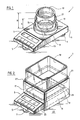
- Figur 2 eine Waage mit einem auf die Standfläche der Waage aufgesetzten rechteckigen Windschutz.
- Die in Figur 1 nur schematisch dargestellte Präzisionswaage 1 mit Anzeige 3 und Bedienungselementen 5 steht auf drei Füssen 7. Auf der Oberseite 9 des Waagengehäuses 11 ist eine Waagschale 13 aufgesetzt, die mit der Waagenmechanik (nicht sichtbar) verbunden ist. Die Waagschale 13 ist von einem von der Oberseite 9 abstehenden Blechring 15 umgeben. Der analog der Waagschale 13 einen runden Querschnitt aufweisende Blechring 15 liegt in einem Abstand von der Peripherie der Waagschale 13.
- Ein zylindrisch unten und oben offener erster Hohlkörper 17 ist in den Blechring 15 eingesteckt und stützt sich auf der Ober fläche 9 des Waagengehäuses 11 ab. Er könnte auch den Blechring 15 aussen umgreifen oder auf diesen aufgesetzt sein. Ein zweiter, ähnlich ausgebildeter oben und unten offener Hohlkörper 19, dessen Aussendurchmesser geringfügig kleiner ist als der Innendurchmesser des ersten Hohlkörpers 17, ist in letzteren hineingeschoben und wird durch einen Zwischenring 21 gehalten. Der Zwischenring 21 liegt selbsthemmend auf der Aussenfläche des zweiten Hohlkörpers 19 auf und besteht aus einem elastischen Material, Z.B. Gummi oder Kunststoff, oder aus einem federnden Metall, dessen Oberfläche mit einem schlecht gleitenden Ueberzug versehen ist.
- In den zweiten, oben liegenden Hohlkörper 19 kann - falls erwünscht - teleskopartig ein weiterer Hohlkörper eingesetzt sein (keine Abbildung).
Die Hohlkörper 17 und 19 können, wie in Figur 1 gezeigt, rund sein. Sie können aber auch einen ovalen oder mehreckigen Querschnitt aufweisen. - Im Beispiel nach Figur 2 ist die Waagschale 13 rechteckförmig und bedeckt im wesentlichen die gesamte Oberfläche 9 des Waagengehäuses 11. Der untere Hohlkörper 17 kann in dieser Ausführung nicht auf der Oberfläche 9 des Waagengehäuses 11 abgestützt werden und steht deshalb auf der Auflagefläche 23 der Waage 1, z.B. auf einem Tisch. Auf der der Bedienungsperson zugekehrten Seite weist der erste Hohlkörper 17 eine Ausnehmung 25 auf, damit die Bedienungs- und Anzeigeinstrumente 3 und 5 ausserhalb des Hohlkörpers 17 frei zugänglich bleiben. Der Zwischenring 21 ist auch in dieser Ausführungsform dem Querschnitt des Hohlkörpers 19 angepasst und liegt auf dessen Oberfläche selbsthemmend an. Besteht der Zwischenring 21 aus Gummi, so legt sich dieser vorwiegend satt an die Ecken an; besteht er jedoch aus federndem Metall, so kann durch entsprechende Biegung der geraden Abschnitte auch ein Druck im Bereich der ebenen Flächen des zweiten Hohlkörpers 19 erreicht werden.
- Die beiden Hohlkörper 17 und 19 sind mit der Waage 1 nicht fest verbunden und können bei Bedarf auf diese bzw. (Fig. 2) auf deren Auflagefläche 23 aufgesetzt werden. Bei niedrigen Wägegütern können die beiden Hohlkörper 17 und 19 in einandergeschoben werden, so dass deren gesamte Höhe H im wesentlichen nur der Höhe h des ersten, unten liegenden Hohlkörpers 17 entspricht. Wird ein Windschutz für hohe Wägegüter benötigt, so kann der innenliegende zweite Hohlkörper 19 aus dem ersten herausgezogen und der Zwischenring 23 nach unten verschoben werden, damit der zweite Hohlkörp er 19 seine eingestellte Lage beibehält. Beim Verringern der Höhe H der als Windschutz dienenden Hohlkörper 17 und 19 lässt sich der zweite Hohlkörper 19 ohne Zuhilfenahme von Werkzeugen durch leichten Druck von oben in den ersten Hohlkörper 17 einschieben.
- In einer weiteren Ausgestaltung der Erfindung kann der Zwischenring 21 auch fest mit der Oberkante 27 des ersten Hohlkörpers 17 verbunden sein, damit beim Herausziehen des zweiten Hohlkörpers 19 der Ring 21 nicht von Hand nach unten verschoben werden muss.
- Auf den zuoberst liegenden Hohlkörper 19 kann ein in den Figuren nicht dargestellter Deckel zum Verschliessen des Wägeraumes aufgesetzt werden. Der Deckel kann als Stülp- oder als Einsteckdeckel ausgebildet sein.
- Die Hohlkörper 17, 19 werden meist aus Glas oder transparentem Kunststoff bestehen. Es kommen jedoch auch andere formbeständige Materialien in Betracht.
Claims (10)
Applications Claiming Priority (2)
| Application Number | Priority Date | Filing Date | Title |
|---|---|---|---|
| CH2379/88 | 1988-06-21 | ||
| CH2379/88A CH675159A5 (de) | 1988-06-21 | 1988-06-21 |
Publications (3)
| Publication Number | Publication Date |
|---|---|
| EP0347520A2 true EP0347520A2 (de) | 1989-12-27 |
| EP0347520A3 EP0347520A3 (de) | 1991-01-30 |
| EP0347520B1 EP0347520B1 (de) | 1993-03-03 |
Family
ID=4232403
Family Applications (1)
| Application Number | Title | Priority Date | Filing Date |
|---|---|---|---|
| EP89102493A Expired - Lifetime EP0347520B1 (de) | 1988-06-21 | 1989-02-14 | Windschutz für Präzisionswaagen |
Country Status (5)
| Country | Link |
|---|---|
| US (1) | US4893686A (de) |
| EP (1) | EP0347520B1 (de) |
| JP (1) | JPH0714825Y2 (de) |
| CH (1) | CH675159A5 (de) |
| DE (2) | DE58903634D1 (de) |
Cited By (1)
| Publication number | Priority date | Publication date | Assignee | Title |
|---|---|---|---|---|
| FR2717898A1 (fr) * | 1994-03-28 | 1995-09-29 | Testut | Balance de tarification automatique. |
Families Citing this family (20)
| Publication number | Priority date | Publication date | Assignee | Title |
|---|---|---|---|---|
| USD315525S (en) | 1988-04-08 | 1991-03-19 | Cobos S.A. | Scale |
| CH679949A5 (de) * | 1990-03-19 | 1992-05-15 | Mettler Toledo Ag | |
| USD394984S (en) | 1995-04-07 | 1998-06-09 | Tefal S.A. | Apparatus for mixing and weighing foodstuffs |
| USD486408S1 (en) | 2002-10-09 | 2004-02-10 | Dart Industries Inc. | Scale with reversible cover |
| DE10330788A1 (de) * | 2003-07-07 | 2005-02-10 | Mettler-Toledo Gmbh | Waage mit Windschutzelement |
| USD526919S1 (en) * | 2004-04-13 | 2006-08-22 | Mettler-Toledo Gmbh | Balance with removable second display |
| DE102004053443B3 (de) * | 2004-11-05 | 2006-05-11 | Sartorius Ag | Oberschalige Waage mit Windschutz |
| GB0719460D0 (en) * | 2007-10-04 | 2007-11-14 | Metryx Ltd | Measurement apparatus and method |
| JP5198488B2 (ja) | 2010-01-26 | 2013-05-15 | 株式会社エー・アンド・デイ | 風防構造を有する秤量装置 |
| DE102010050225A1 (de) | 2010-11-04 | 2012-05-10 | Mettler-Toledo Ag | Windschutzvorrichtung für eine Waage |
| US8627786B2 (en) * | 2011-05-10 | 2014-01-14 | Peters Arthur | Pet feeding apparatus |
| CN102435271A (zh) * | 2011-10-25 | 2012-05-02 | 苏州弘贸纺织有限公司 | 防止布料称重过量的电子称 |
| CN102538925A (zh) * | 2012-02-09 | 2012-07-04 | 吴江市隆泰喷织厂 | 用于布料称重的电子称 |
| JP6247134B2 (ja) * | 2014-03-28 | 2017-12-13 | 新光電子株式会社 | 側面風防体を備える秤量装置 |
| DE102015103766A1 (de) * | 2015-03-15 | 2016-09-15 | Waldner Ag | Wägeabzug |
| CN105387918B (zh) * | 2015-09-29 | 2018-10-26 | 诸暨马谷亲科技有限公司 | 一种可变形式厨房用电子称 |
| EP3557199B1 (de) * | 2018-04-17 | 2021-01-06 | Mettler-Toledo GmbH | Laborwaage mit einer modular aufgebauten wägeraumrückwand |
| CN110803401A (zh) * | 2019-11-02 | 2020-02-18 | 南京普维森包装有限公司 | 一种卸料口易撕且减少残留的集装袋内袋 |
| EP4365558A4 (de) * | 2021-06-28 | 2024-08-07 | A&D Company, Limited | Waage mit doppeltem zugschild |
| US20230152147A1 (en) * | 2021-11-18 | 2023-05-18 | VersaWare Technologies, Inc. | Automated weight scale nutrient and caloric monitoring system |
Family Cites Families (6)
| Publication number | Priority date | Publication date | Assignee | Title |
|---|---|---|---|---|
| US2732199A (en) * | 1956-01-24 | Meinig | ||
| CH560893A5 (en) * | 1974-03-27 | 1975-04-15 | Mettler Instrumente Ag | Wind shield for open pan precision balances - is collapsible to occupy minimum space when not in use |
| JPS5443989Y2 (de) * | 1978-06-22 | 1979-12-18 | ||
| DE3508873C1 (de) * | 1985-03-13 | 1986-06-05 | Sartorius GmbH, 3400 Göttingen | Oberschalige Waage |
| CH671630A5 (de) * | 1986-12-15 | 1989-09-15 | Mettler Instrumente Ag | |
| CH673154A5 (de) * | 1986-12-16 | 1990-02-15 | Sartorius Gmbh |
-
1988
- 1988-06-21 CH CH2379/88A patent/CH675159A5/de not_active IP Right Cessation
-
1989
- 1989-01-11 JP JP1989002611U patent/JPH0714825Y2/ja not_active Expired - Lifetime
- 1989-02-14 DE DE8989102493T patent/DE58903634D1/de not_active Expired - Fee Related
- 1989-02-14 EP EP89102493A patent/EP0347520B1/de not_active Expired - Lifetime
- 1989-04-03 DE DE8904088U patent/DE8904088U1/de not_active Expired
- 1989-05-01 US US07/345,780 patent/US4893686A/en not_active Expired - Fee Related
Cited By (1)
| Publication number | Priority date | Publication date | Assignee | Title |
|---|---|---|---|---|
| FR2717898A1 (fr) * | 1994-03-28 | 1995-09-29 | Testut | Balance de tarification automatique. |
Also Published As
| Publication number | Publication date |
|---|---|
| EP0347520B1 (de) | 1993-03-03 |
| CH675159A5 (de) | 1990-08-31 |
| US4893686A (en) | 1990-01-16 |
| JPH02128530U (de) | 1990-10-23 |
| DE8904088U1 (de) | 1989-06-08 |
| JPH0714825Y2 (ja) | 1995-04-10 |
| EP0347520A3 (de) | 1991-01-30 |
| DE58903634D1 (de) | 1993-04-08 |
Similar Documents
| Publication | Publication Date | Title |
|---|---|---|
| EP0347520B1 (de) | Windschutz für Präzisionswaagen | |
| DE2903780C2 (de) | Mehrreihige Tastatur für Schreib- o. ähnliche Maschinen | |
| DE68914521T2 (de) | Elektronische Waage. | |
| DE69006251T2 (de) | Universale Einschliessung gegen Verdampfung. | |
| DE2218156A1 (de) | Objekttragerfinger fur Mikroskop | |
| EP1642097B1 (de) | Waage mit windschutzelement | |
| CH619049A5 (en) | Maximum-demand meter consisting of an electricity meter re-equipped with an additional device. | |
| DE202012006283U1 (de) | Höhenverstellbarer Tisch | |
| DE2721030C3 (de) | Hülle mit Innenpolster für eine Personenwaage | |
| DE102010061096B4 (de) | Abnehmbarer Windschutz für eine Präzisionswaage | |
| DE3604574C1 (en) | Pipe notching device | |
| EP1031793A2 (de) | Kochmulde mit einem Muldenrahmen | |
| DE10254604B4 (de) | Tischmöbel | |
| DE2222891C3 (de) | Herdmulde | |
| EP1935283A1 (de) | Küchenmöbel | |
| DE2922372C2 (de) | Tischkalender | |
| DE1204191B (de) | Ordnerkasten | |
| DE8522425U1 (de) | Wägevorrichtung | |
| EP1038471A2 (de) | Schreibtisch mit einer Ablagerinne | |
| DE29708677U1 (de) | Tisch, insbesondere Arbeitstisch | |
| DE1685923U (de) | Glasplattenbefestigung. | |
| DE8802921U1 (de) | Luftdüsenplatte als Einbauteil für Doppelbodenplatten | |
| DE7919930U1 (de) | Tisch, insbesondere zur verwendung im freien | |
| DE9100686U1 (de) | Möbel, insbesondere Arbeitsmöbel | |
| DE1743264U (de) | Einrichtung zur einstellung des ansprechbereiches von druckschaltern. |
Legal Events
| Date | Code | Title | Description |
|---|---|---|---|
| PUAI | Public reference made under article 153(3) epc to a published international application that has entered the european phase |
Free format text: ORIGINAL CODE: 0009012 |
|
| AK | Designated contracting states |
Kind code of ref document: A2 Designated state(s): DE FR GB IT NL |
|
| RAP1 | Party data changed (applicant data changed or rights of an application transferred) |
Owner name: METTLER-TOLEDO AG |
|
| PUAL | Search report despatched |
Free format text: ORIGINAL CODE: 0009013 |
|
| AK | Designated contracting states |
Kind code of ref document: A3 Designated state(s): DE FR GB IT NL |
|
| 17P | Request for examination filed |
Effective date: 19901220 |
|
| 17Q | First examination report despatched |
Effective date: 19920410 |
|
| GRAA | (expected) grant |
Free format text: ORIGINAL CODE: 0009210 |
|
| AK | Designated contracting states |
Kind code of ref document: B1 Designated state(s): DE FR GB IT NL |
|
| PG25 | Lapsed in a contracting state [announced via postgrant information from national office to epo] |
Ref country code: IT Free format text: LAPSE BECAUSE OF FAILURE TO SUBMIT A TRANSLATION OF THE DESCRIPTION OR TO PAY THE FEE WITHIN THE PRE;WARNING: LAPSES OF ITALIAN PATENTS WITH EFFECTIVE DATE BEFORE 2007 MAY HAVE OCCURRED AT ANY TIME BEFORE 2007. THE CORRECT EFFECTIVE DATE MAY BE DIFFERENT FROM THE ONE RECORDED.SCRIBED TIME-LIMIT Effective date: 19930303 Ref country code: NL Effective date: 19930303 |
|
| GBT | Gb: translation of ep patent filed (gb section 77(6)(a)/1977) |
Effective date: 19930304 |
|
| REF | Corresponds to: |
Ref document number: 58903634 Country of ref document: DE Date of ref document: 19930408 |
|
| ET | Fr: translation filed | ||
| NLV1 | Nl: lapsed or annulled due to failure to fulfill the requirements of art. 29p and 29m of the patents act | ||
| PGFP | Annual fee paid to national office [announced via postgrant information from national office to epo] |
Ref country code: DE Payment date: 19931129 Year of fee payment: 7 |
|
| PLBE | No opposition filed within time limit |
Free format text: ORIGINAL CODE: 0009261 |
|
| STAA | Information on the status of an ep patent application or granted ep patent |
Free format text: STATUS: NO OPPOSITION FILED WITHIN TIME LIMIT |
|
| 26N | No opposition filed | ||
| PGFP | Annual fee paid to national office [announced via postgrant information from national office to epo] |
Ref country code: FR Payment date: 19941128 Year of fee payment: 7 |
|
| PGFP | Annual fee paid to national office [announced via postgrant information from national office to epo] |
Ref country code: GB Payment date: 19950213 Year of fee payment: 7 |
|
| PG25 | Lapsed in a contracting state [announced via postgrant information from national office to epo] |
Ref country code: GB Effective date: 19960214 |
|
| GBPC | Gb: european patent ceased through non-payment of renewal fee |
Effective date: 19960214 |
|
| PG25 | Lapsed in a contracting state [announced via postgrant information from national office to epo] |
Ref country code: FR Effective date: 19961031 |
|
| PG25 | Lapsed in a contracting state [announced via postgrant information from national office to epo] |
Ref country code: DE Effective date: 19961101 |
|
| REG | Reference to a national code |
Ref country code: FR Ref legal event code: ST |