EP0344093A2 - Elément de fixation ayant une douille d'expansion - Google Patents
Elément de fixation ayant une douille d'expansion Download PDFInfo
- Publication number
- EP0344093A2 EP0344093A2 EP89730104A EP89730104A EP0344093A2 EP 0344093 A2 EP0344093 A2 EP 0344093A2 EP 89730104 A EP89730104 A EP 89730104A EP 89730104 A EP89730104 A EP 89730104A EP 0344093 A2 EP0344093 A2 EP 0344093A2
- Authority
- EP
- European Patent Office
- Prior art keywords
- sleeve
- fastening element
- plate
- core
- opening
- Prior art date
- Legal status (The legal status is an assumption and is not a legal conclusion. Google has not performed a legal analysis and makes no representation as to the accuracy of the status listed.)
- Withdrawn
Links
Images
Classifications
-
- B—PERFORMING OPERATIONS; TRANSPORTING
- B65—CONVEYING; PACKING; STORING; HANDLING THIN OR FILAMENTARY MATERIAL
- B65G—TRANSPORT OR STORAGE DEVICES, e.g. CONVEYORS FOR LOADING OR TIPPING, SHOP CONVEYOR SYSTEMS OR PNEUMATIC TUBE CONVEYORS
- B65G39/00—Rollers, e.g. drive rollers, or arrangements thereof incorporated in roller-ways or other types of mechanical conveyors
- B65G39/10—Arrangements of rollers
- B65G39/12—Arrangements of rollers mounted on framework
-
- F—MECHANICAL ENGINEERING; LIGHTING; HEATING; WEAPONS; BLASTING
- F16—ENGINEERING ELEMENTS AND UNITS; GENERAL MEASURES FOR PRODUCING AND MAINTAINING EFFECTIVE FUNCTIONING OF MACHINES OR INSTALLATIONS; THERMAL INSULATION IN GENERAL
- F16B—DEVICES FOR FASTENING OR SECURING CONSTRUCTIONAL ELEMENTS OR MACHINE PARTS TOGETHER, e.g. NAILS, BOLTS, CIRCLIPS, CLAMPS, CLIPS OR WEDGES; JOINTS OR JOINTING
- F16B13/00—Dowels or other devices fastened in walls or the like by inserting them in holes made therein for that purpose
- F16B13/12—Separate metal or non-separate or non-metal dowel sleeves fastened by inserting the screw, nail or the like
- F16B13/122—Separate metal or non-separate or non-metal dowel sleeves fastened by inserting the screw, nail or the like made from a sheet-metal blank
-
- F—MECHANICAL ENGINEERING; LIGHTING; HEATING; WEAPONS; BLASTING
- F16—ENGINEERING ELEMENTS AND UNITS; GENERAL MEASURES FOR PRODUCING AND MAINTAINING EFFECTIVE FUNCTIONING OF MACHINES OR INSTALLATIONS; THERMAL INSULATION IN GENERAL
- F16B—DEVICES FOR FASTENING OR SECURING CONSTRUCTIONAL ELEMENTS OR MACHINE PARTS TOGETHER, e.g. NAILS, BOLTS, CIRCLIPS, CLAMPS, CLIPS OR WEDGES; JOINTS OR JOINTING
- F16B13/00—Dowels or other devices fastened in walls or the like by inserting them in holes made therein for that purpose
- F16B13/12—Separate metal or non-separate or non-metal dowel sleeves fastened by inserting the screw, nail or the like
- F16B13/126—Separate metal or non-separate or non-metal dowel sleeves fastened by inserting the screw, nail or the like fastened by inserting an unthreaded element, e.g. pin or nail
-
- F—MECHANICAL ENGINEERING; LIGHTING; HEATING; WEAPONS; BLASTING
- F16—ENGINEERING ELEMENTS AND UNITS; GENERAL MEASURES FOR PRODUCING AND MAINTAINING EFFECTIVE FUNCTIONING OF MACHINES OR INSTALLATIONS; THERMAL INSULATION IN GENERAL
- F16B—DEVICES FOR FASTENING OR SECURING CONSTRUCTIONAL ELEMENTS OR MACHINE PARTS TOGETHER, e.g. NAILS, BOLTS, CIRCLIPS, CLAMPS, CLIPS OR WEDGES; JOINTS OR JOINTING
- F16B19/00—Bolts without screw-thread; Pins, including deformable elements; Rivets
- F16B19/002—Resiliently deformable pins
- F16B19/004—Resiliently deformable pins made in one piece
-
- F—MECHANICAL ENGINEERING; LIGHTING; HEATING; WEAPONS; BLASTING
- F16—ENGINEERING ELEMENTS AND UNITS; GENERAL MEASURES FOR PRODUCING AND MAINTAINING EFFECTIVE FUNCTIONING OF MACHINES OR INSTALLATIONS; THERMAL INSULATION IN GENERAL
- F16B—DEVICES FOR FASTENING OR SECURING CONSTRUCTIONAL ELEMENTS OR MACHINE PARTS TOGETHER, e.g. NAILS, BOLTS, CIRCLIPS, CLAMPS, CLIPS OR WEDGES; JOINTS OR JOINTING
- F16B19/00—Bolts without screw-thread; Pins, including deformable elements; Rivets
- F16B19/04—Rivets; Spigots or the like fastened by riveting
- F16B19/08—Hollow rivets; Multi-part rivets
- F16B19/10—Hollow rivets; Multi-part rivets fastened by expanding mechanically
- F16B19/1027—Multi-part rivets
- F16B19/1036—Blind rivets
- F16B19/1081—Blind rivets fastened by a drive-pin
-
- F—MECHANICAL ENGINEERING; LIGHTING; HEATING; WEAPONS; BLASTING
- F16—ENGINEERING ELEMENTS AND UNITS; GENERAL MEASURES FOR PRODUCING AND MAINTAINING EFFECTIVE FUNCTIONING OF MACHINES OR INSTALLATIONS; THERMAL INSULATION IN GENERAL
- F16B—DEVICES FOR FASTENING OR SECURING CONSTRUCTIONAL ELEMENTS OR MACHINE PARTS TOGETHER, e.g. NAILS, BOLTS, CIRCLIPS, CLAMPS, CLIPS OR WEDGES; JOINTS OR JOINTING
- F16B41/00—Measures against loss of bolts, nuts, or pins; Measures against unauthorised operation of bolts, nuts or pins
- F16B41/002—Measures against loss of bolts, nuts or pins
-
- F—MECHANICAL ENGINEERING; LIGHTING; HEATING; WEAPONS; BLASTING
- F16—ENGINEERING ELEMENTS AND UNITS; GENERAL MEASURES FOR PRODUCING AND MAINTAINING EFFECTIVE FUNCTIONING OF MACHINES OR INSTALLATIONS; THERMAL INSULATION IN GENERAL
- F16C—SHAFTS; FLEXIBLE SHAFTS; ELEMENTS OR CRANKSHAFT MECHANISMS; ROTARY BODIES OTHER THAN GEARING ELEMENTS; BEARINGS
- F16C13/00—Rolls, drums, discs, or the like; Bearings or mountings therefor
- F16C13/02—Bearings
-
- Y—GENERAL TAGGING OF NEW TECHNOLOGICAL DEVELOPMENTS; GENERAL TAGGING OF CROSS-SECTIONAL TECHNOLOGIES SPANNING OVER SEVERAL SECTIONS OF THE IPC; TECHNICAL SUBJECTS COVERED BY FORMER USPC CROSS-REFERENCE ART COLLECTIONS [XRACs] AND DIGESTS
- Y10—TECHNICAL SUBJECTS COVERED BY FORMER USPC
- Y10S—TECHNICAL SUBJECTS COVERED BY FORMER USPC CROSS-REFERENCE ART COLLECTIONS [XRACs] AND DIGESTS
- Y10S411/00—Expanded, threaded, driven, headed, tool-deformed, or locked-threaded fastener
- Y10S411/913—Self-expanding anchor
Definitions
- the invention relates to a fastener according to the features of the preamble of the main claim.
- Such fasteners are known, for example, as expansion anchors for insertion in masonry bores, for fastening a plate to masonry (DE-A-27 14 503) or according to German utility model 78 14 794 for fastening elements to a plate, but they are only used to a small extent be claimed for shear.
- the object of the invention is to design a fastener of the aforementioned type so that it can also be subjected to bending with the part protruding through a plate. It should be inexpensive and easy to assemble and disassemble in all positions without special tools. This object is achieved with the features in the characterizing part of claim 1.
- the expanding core rests with a head on the collar of the sleeve, which has a rising area which widens in the direction of insertion in front of the inner edge and a cylindrical area in front of which the load to be carried can be supported.
- the head of the core is used for gripping when removing from the sleeve, which can be made of a solid thermoplastic and has incisions for expanding noses of the core, which presses the sleeve with its contact area against the opening of the plate and has an excess, depending on Size of the spread element and material hardness is 0.05 to 0.5 mm.
- the sleeve can also be made of metal in the form of a sheet metal strip, which preferably has five incisions.
- This sheet metal part is given a cylindrical area when wound on a mandrel in the incision-free section, to which the incised part is connected as a hexagon with a cone area, the inner wall area, the system area and the collar.
- the edges of the sheet metal part form a slot.
- the core is made of plastic and has a truncated cone-shaped tip, the truncated cone end of which has a larger diameter than the adjoining cylindrical system area to prevent it from accidentally slipping out.
- the core at the tip has a thread-like connecting element to a neck with a head, with which the sleeve can also be pulled out of the plate via the core.
- the head is placed in front of the opening at the tip of the sleeve and the thread is guided through the slot between the edges of the sheet metal strip into the interior of the sleeve.
- the fastening elements according to the invention can - due to the possibility of absorbing bending forces - also hold bearings in conveyor tracks if used appropriately. They can be serviced or the idlers can be inspected.
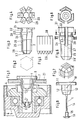
- Fig. 1 shows the end of a conveyor track support roller 6, which is provided with a roller insert 5 and is thus supported via bearings 4 and a holding element 3 on a sleeve 2, the contact area 2.2 of a core 1 against the wall of an opening 8 of a plate 7 or side cheek of the conveyor track is pressed.
- this sleeve which is made of metal
- the leakage resistance to reduce electrostatic charges is less than 10 million ohms. These electrostatic charges can arise when the rollers are turned and should be discharged as far as possible. If the perforated side cheek was painted before assembly, the paint in the breakthrough area is scraped off when the metal sleeve is hammered in and a perfect electrical connection is created between the sleeve and the side cheek.
- the sleeve 2 shown in FIGS. 1 and 3 is made from an approximately 1 mm thick sheet which is shown in the development in FIG. 5. It has five incisions 2.8 on one end and five pointed cutouts or edge sections on the other end, so that the part remaining between them forms a truncated pyramid 2.6 after rolling up.
- the non-incised area 2.5 becomes cylindrical when rolling, and the incised part initially forms an increasing area 2.4 with a larger diameter with an inner edge 2.3 that is bent towards the core, which is followed by a hexagonal contact area 2.2 for the opening 8 with angled collar areas 2.1.
- the sleeve is inserted when it is inserted into the opening and then quasi returns to its initial diameter in the opening and snaps into the opening.
- the core 1 shown in FIG. 9 is hammered into this sleeve 2.
- the contact area 2.2 of the sleeve 2 it has a truncated cone 1.3 with a contact area 1.2 and a head 1.1. So that the core 1 cannot accidentally slip out of the sleeve 2, the largest diameter of the truncated cone 1.3 is approximately 0.2 mm larger than the diameter of the contact area 1.2.
- the truncated cone 1.3 is connected to the truncated cone 1.3 with a cylindrical neck 1.5 which is held in the truncated cone tip 2.6.
- the core 1 is first gripped and pulled back on its gripping head 1.1, the connecting element 1.4 curved in FIG. 1 being stretched. You can then the core 1 on the gripping head 1.1 well Detect and pull the sleeve 2 out of the opening 8 via the connecting element 1.4 and the head 1.6.
- a sleeve 2 made of plastic according to FIGS. 6 to 8 can also be used for certain applications.
- This sleeve also lies with a collar 2.1 on the outside of the plate 7 or side cheek and fills the opening 8 with a cylindrical or hexagonal contact area 2.2 and lies with the inner edge 2.3 on the inner wall 7.1.
- the sleeve 2 is compressed when it is inserted into the opening 8 via the rising area 2.4, the three incisions 2.8 shown in FIGS. 6 and 7 being narrowed.
- This sleeve also has a cylindrical region 2.5 for carrying the holding element 3 and a longer opening 2.7 for passing the connecting element 1.4 of the core 1 with a pointed head 1.6, which lies in front of the truncated cone 2.6.
- Spreading noses of the core 1 protrude into the incisions 2.8.
- One of these expanding noses 1.8 is shown in dash-dot lines in FIG. 9.
Landscapes
- Engineering & Computer Science (AREA)
- General Engineering & Computer Science (AREA)
- Mechanical Engineering (AREA)
- Dowels (AREA)
- Insertion Pins And Rivets (AREA)
Applications Claiming Priority (2)
| Application Number | Priority Date | Filing Date | Title |
|---|---|---|---|
| DE3813892 | 1988-04-20 | ||
| DE3813892A DE3813892A1 (de) | 1988-04-20 | 1988-04-20 | Befestigungselement mit einer spreizhuelse |
Publications (2)
| Publication Number | Publication Date |
|---|---|
| EP0344093A2 true EP0344093A2 (fr) | 1989-11-29 |
| EP0344093A3 EP0344093A3 (fr) | 1990-12-05 |
Family
ID=6352821
Family Applications (1)
| Application Number | Title | Priority Date | Filing Date |
|---|---|---|---|
| EP19890730104 Withdrawn EP0344093A3 (fr) | 1988-04-20 | 1989-04-13 | Elément de fixation ayant une douille d'expansion |
Country Status (3)
| Country | Link |
|---|---|
| US (1) | US4978266A (fr) |
| EP (1) | EP0344093A3 (fr) |
| DE (1) | DE3813892A1 (fr) |
Cited By (2)
| Publication number | Priority date | Publication date | Assignee | Title |
|---|---|---|---|---|
| EP2157037A3 (fr) * | 2008-08-21 | 2010-09-29 | Quintall B.V. | Transporteur à rouleaux |
| FR2982000A1 (fr) * | 2011-10-27 | 2013-05-03 | Peugeot Citroen Automobiles Sa | Agencement et procede de montage d'un arbre rotatif sur un carter, notamment sur un carter dans une transmission automobile. |
Families Citing this family (10)
| Publication number | Priority date | Publication date | Assignee | Title |
|---|---|---|---|---|
| US5040803A (en) * | 1990-04-23 | 1991-08-20 | Cieslik David R | Cavity sealing arrangement and method |
| AU664732B2 (en) * | 1993-03-15 | 1995-11-30 | Fabrica De Aco Paulista Ltda | Belt conveyor roller |
| US5378030A (en) * | 1993-04-14 | 1995-01-03 | E. J. Brooks Company | Keyless locking device and method |
| US5725261A (en) * | 1995-12-20 | 1998-03-10 | Mfi Associates, Inc. | Identification tag and anchor for use in displaying indicia including graphics and text |
| ITMO20020240A1 (it) * | 2002-09-03 | 2004-03-04 | Kemac S R L | Dispositivo per l'ancoraggio ed il trascinamento di rulli in box a rulli. |
| DE10351716B4 (de) * | 2002-11-06 | 2005-04-14 | Richard Bergner Verbindungstechnik Gmbh & Co. Kg | Trägerteil mit Fixierbolzen |
| US6782996B1 (en) * | 2003-02-13 | 2004-08-31 | Rapistan Systems Advertising Corp. | Axle cartridge for conveyor roller |
| US7413424B2 (en) * | 2003-06-03 | 2008-08-19 | Brueninghaus Hydromatik Gmbh | Gear pump and holding element therefor |
| DE10325025B4 (de) * | 2003-06-03 | 2005-11-17 | Brueninghaus Hydromatik Gmbh | Zahnradpumpe und Halteglied hierfür |
| US11580885B2 (en) * | 2018-09-28 | 2023-02-14 | Honeywell International Inc. | Tamper proof seal assembly |
Family Cites Families (15)
| Publication number | Priority date | Publication date | Assignee | Title |
|---|---|---|---|---|
| US1889807A (en) * | 1930-04-22 | 1932-12-06 | William B Wharton | Fastening device |
| US1862152A (en) * | 1930-05-06 | 1932-06-07 | William B Wharton | Fastening device |
| US2555292A (en) * | 1947-12-12 | 1951-05-29 | Illinois Tool Works | Fastener |
| DE1149814B (de) * | 1961-05-10 | 1963-06-06 | Quante Wilhelm | Isolationswiderstands-Messgeraet, insbesondere fuer Fernmeldekabel |
| US3217584A (en) * | 1962-12-11 | 1965-11-16 | United Carr Inc | Snap fastener stud and method of forming same |
| US3710674A (en) * | 1970-12-18 | 1973-01-16 | Meteor Res Ltd | Expandable fastener |
| DE2242981A1 (de) * | 1972-09-01 | 1974-03-07 | United Carr Gmbh | Loesbare verbindung |
| FR2358580A1 (fr) * | 1976-07-16 | 1978-02-10 | Comet | Perfectionnements aux cages pour ecrous prisonniers et aux appareils et procedes pour fabriquer de telles cages |
| US4059180A (en) * | 1976-12-02 | 1977-11-22 | Rexnord Inc. | Roller assembly with improved mounting means |
| US4133245A (en) * | 1976-12-16 | 1979-01-09 | Allied Moulded Products, Inc. | Fastening device |
| DE7708798U1 (de) * | 1977-03-22 | 1977-07-14 | Brauckmann Industrielle Befestigungselemente Gmbh & Co Kg, 5880 Luedenscheid | Vorrichtung zur befestigung von haengeschraenken, garderoben und dergleichen an waenden |
| DE2714503C2 (de) * | 1977-04-01 | 1983-05-26 | Anton 8500 Nürnberg Gerhard | Spreizdübel zur Abstandsbefestigung eines Bauteils |
| US4148386A (en) * | 1978-02-17 | 1979-04-10 | Rexnord Inc. | Conveyor roller mounting device with curved surfaces |
| DE2809596A1 (de) * | 1978-03-06 | 1979-09-20 | Merk Gmbh Telefonbau Fried | Schaltungsanordnung zur erfassung von erdschluessen zweiadriger meldeleitungen |
| DE3140861A1 (de) * | 1981-10-14 | 1983-04-21 | Hilti AG, 9494 Schaan | Verfahren, stuetzkoerper und duebel zur abstandsbefestigung von fassadenplatten bzw. fassadentraegern |
-
1988
- 1988-04-20 DE DE3813892A patent/DE3813892A1/de active Granted
-
1989
- 1989-04-13 EP EP19890730104 patent/EP0344093A3/fr not_active Withdrawn
- 1989-04-20 US US07/340,991 patent/US4978266A/en not_active Expired - Fee Related
Cited By (2)
| Publication number | Priority date | Publication date | Assignee | Title |
|---|---|---|---|---|
| EP2157037A3 (fr) * | 2008-08-21 | 2010-09-29 | Quintall B.V. | Transporteur à rouleaux |
| FR2982000A1 (fr) * | 2011-10-27 | 2013-05-03 | Peugeot Citroen Automobiles Sa | Agencement et procede de montage d'un arbre rotatif sur un carter, notamment sur un carter dans une transmission automobile. |
Also Published As
| Publication number | Publication date |
|---|---|
| EP0344093A3 (fr) | 1990-12-05 |
| US4978266A (en) | 1990-12-18 |
| DE3813892C2 (fr) | 1990-05-10 |
| DE3813892A1 (de) | 1989-11-23 |
Similar Documents
| Publication | Publication Date | Title |
|---|---|---|
| EP0192913B1 (fr) | Cheville expansible à indication de serrage | |
| DE60301694T2 (de) | Spreizdübel mit einer komprimierbaren Zone | |
| EP0905385A2 (fr) | Cheville d'expansion | |
| EP0344093A2 (fr) | Elément de fixation ayant une douille d'expansion | |
| DE2736012A1 (de) | Befestiger zur befestigung eines teils an plattenmaterial | |
| CH631521A5 (de) | Verankerungsbuchse. | |
| DE60218621T2 (de) | Befestigungsvorrichtung | |
| DE2744036C3 (de) | Vorrichtung zum Befestigen einer Dacheindeckungsplatte | |
| EP0742374A1 (fr) | Elément de fixation comprenant un boulon d'ancrage et une câle d'expansion | |
| CH622861A5 (fr) | ||
| EP0118006B1 (fr) | Cheville à percussion | |
| EP1375939A2 (fr) | Montage d'une unité de palier axial à rouleaux | |
| EP0171354B1 (fr) | Cheville à écartement | |
| DE2029407C3 (de) | Spreizdübel mit Sperrvorrichtung | |
| DE202008013822U1 (de) | Bodenstütze | |
| DE3146702A1 (de) | Verbindungsvorrichtung | |
| CH636933A5 (en) | Device for attaching an element to a pipe | |
| DE3030643A1 (de) | Nagelduebel | |
| DE3336809C2 (de) | Kunststoffdübel für Leichtbetone, insbesondere Gas- oder Schaumbetone | |
| EP0738835A1 (fr) | Cheville à enveloppe en forme de crible | |
| EP0793025A1 (fr) | Cheville en métal d'ancrage pour panneaux muraux minces | |
| DE8003978U1 (de) | Klemmkopfdübel aus Kunststoff | |
| DE102018116974A1 (de) | Spreizanker | |
| DE10162072A1 (de) | Befestigungselement mit einem Schaft und einem Kopf | |
| DE3151660A1 (de) | "befestigungselement mit ankerbolzen und verankerungsstift" |
Legal Events
| Date | Code | Title | Description |
|---|---|---|---|
| PUAI | Public reference made under article 153(3) epc to a published international application that has entered the european phase |
Free format text: ORIGINAL CODE: 0009012 |
|
| AK | Designated contracting states |
Kind code of ref document: A2 Designated state(s): BE DE FR GB IT LU NL SE |
|
| 17P | Request for examination filed |
Effective date: 19900327 |
|
| PUAL | Search report despatched |
Free format text: ORIGINAL CODE: 0009013 |
|
| RHK1 | Main classification (correction) |
Ipc: B65G 39/09 |
|
| AK | Designated contracting states |
Kind code of ref document: A3 Designated state(s): BE DE FR GB IT LU NL SE |
|
| STAA | Information on the status of an ep patent application or granted ep patent |
Free format text: STATUS: THE APPLICATION IS DEEMED TO BE WITHDRAWN |
|
| 18D | Application deemed to be withdrawn |
Effective date: 19910606 |