EP0343951A2 - Beschichtungs- und Reinigungsverfahren bei dem ein thermoplastisches Material benutzt wird - Google Patents
Beschichtungs- und Reinigungsverfahren bei dem ein thermoplastisches Material benutzt wird Download PDFInfo
- Publication number
- EP0343951A2 EP0343951A2 EP89305242A EP89305242A EP0343951A2 EP 0343951 A2 EP0343951 A2 EP 0343951A2 EP 89305242 A EP89305242 A EP 89305242A EP 89305242 A EP89305242 A EP 89305242A EP 0343951 A2 EP0343951 A2 EP 0343951A2
- Authority
- EP
- European Patent Office
- Prior art keywords
- heat
- soluble material
- image
- remover
- substrate
- Prior art date
- Legal status (The legal status is an assumption and is not a legal conclusion. Google has not performed a legal analysis and makes no representation as to the accuracy of the status listed.)
- Granted
Links
Images


Classifications
-
- B—PERFORMING OPERATIONS; TRANSPORTING
- B41—PRINTING; LINING MACHINES; TYPEWRITERS; STAMPS
- B41M—PRINTING, DUPLICATING, MARKING, OR COPYING PROCESSES; COLOUR PRINTING
- B41M5/00—Duplicating or marking methods; Sheet materials for use therein
- B41M5/26—Thermography ; Marking by high energetic means, e.g. laser otherwise than by burning, and characterised by the material used
- B41M5/382—Contact thermal transfer or sublimation processes
- B41M5/38207—Contact thermal transfer or sublimation processes characterised by aspects not provided for in groups B41M5/385 - B41M5/395
-
- B—PERFORMING OPERATIONS; TRANSPORTING
- B41—PRINTING; LINING MACHINES; TYPEWRITERS; STAMPS
- B41J—TYPEWRITERS; SELECTIVE PRINTING MECHANISMS, i.e. MECHANISMS PRINTING OTHERWISE THAN FROM A FORME; CORRECTION OF TYPOGRAPHICAL ERRORS
- B41J17/00—Mechanisms for manipulating page-width impression-transfer material, e.g. carbon paper
- B41J17/38—Mechanisms for manipulating page-width impression-transfer material, e.g. carbon paper for dealing with the impression-transfer material after use
- B41J17/40—Mechanisms for manipulating page-width impression-transfer material, e.g. carbon paper for dealing with the impression-transfer material after use for retracting sheets for re-use
-
- B—PERFORMING OPERATIONS; TRANSPORTING
- B41—PRINTING; LINING MACHINES; TYPEWRITERS; STAMPS
- B41J—TYPEWRITERS; SELECTIVE PRINTING MECHANISMS, i.e. MECHANISMS PRINTING OTHERWISE THAN FROM A FORME; CORRECTION OF TYPOGRAPHICAL ERRORS
- B41J31/00—Ink ribbons; Renovating or testing ink ribbons
- B41J31/14—Renovating or testing ink ribbons
-
- Y—GENERAL TAGGING OF NEW TECHNOLOGICAL DEVELOPMENTS; GENERAL TAGGING OF CROSS-SECTIONAL TECHNOLOGIES SPANNING OVER SEVERAL SECTIONS OF THE IPC; TECHNICAL SUBJECTS COVERED BY FORMER USPC CROSS-REFERENCE ART COLLECTIONS [XRACs] AND DIGESTS
- Y10—TECHNICAL SUBJECTS COVERED BY FORMER USPC
- Y10T—TECHNICAL SUBJECTS COVERED BY FORMER US CLASSIFICATION
- Y10T156/00—Adhesive bonding and miscellaneous chemical manufacture
- Y10T156/11—Methods of delaminating, per se; i.e., separating at bonding face
- Y10T156/1153—Temperature change for delamination [e.g., heating during delaminating, etc.]
Definitions
- the present invention relates to a coating method for making a coat of heat-soluble material and a coating apparatus, as well as a cleaning method of the coating of the heat-soluble material, and further a printer, printed matter, and a display apparatus made by utilizing them.
- thermal transfer printer At present, as a personal and handy printer, there is a thermal transfer printer.
- the defects of this apparatus are slow recording speed and high running cost, i.e., high unit price per sheet.
- a thermal printer using a line head thermal head made by arranging the heating elements in full width of a sheet of paper
- a sheet of thermal ink-transfer ribbon [a ribbon made of PET (polyethylene terephthalate) having a thickness of 3 ⁇ 6 ⁇ coated with heat-soluble ink in 3 ⁇ 5 ⁇ ] per sheet of A4 size print.
- the printing cost is very high.
- the serial type printer the ribbon is used only for the portions to be printed, so that the consumption of ribbon is relatively small. In reality, however, in the latter system, the ribbon requires to be housed in a cassette so as to facilitate the ribbon handling, and it costs higher than the line head type printer.
- a coating method of the present invention comprises the steps of supplying a heat-soluble material melted under heating, onto a substrate laying a remover on the heat-soluble material, cooling the heat-soluble material to solidify, and peeling off the remover whereby a coating of heat-soluble material is formed on the substrate.
- thermo transfer coating a coating of heat-soluble material (e.g., thermal transfer coating) can be easily produced. Further, as it is possible to make regeneration of the thermal ink-transfer ribbon (a thin polyethylene terephthalate sheet to which heat-soluble ink is applied) in an apparatus, a printer having a low running cost can be obtained.
- a further object of the present invention is to provide a method of cleaning a printed matter soiled with a heat-soluble material.
- a still further object of the invention is to obtain, by utilizing the above method, an erasable paper and a printer.
- the heat-soluble material does not remain at all on the substrate, and the heat-soluble material is completely transferred to the remover. Namely, the substrate can be cleaned.
- letters and images formed on a plastic sheet by thermal transfer can be erased, so that it is possible to obtain an erasable paper and an apparatus for the designed object.
- a further object of the present invention is to obtain a display apparatus using the above coating method and cleaning method utilizing thermal transfer.
- Figs. 1 a), b) are illustrative views of a coating method according to the present invention.
- the part 101 is a substrate or support member.
- the substrate 101 may be composed of a generally available material which does not permeate liquid such as plastics, rubber, metal, paper having no liquid permeability, ceramics, or the like.
- a heat-soluble material 102 which has been heated to melt as in Fig. 1 a) is supplied, and on this molten heat-soluble material a remover 103 is laid.
- a heat-soluble material for the purpose of regenerating the thermal ink-transfer ribbon which is an object of the present invention a material comprising as the main components wax and color pigment can be used.
- Other heat-soluble resins e.g., epoxy resin, acryl resin, etc.
- Preferred material is a plastic sheet. From the points of cost and strength, a sheet of polyethylene terephthalate is most preferred.
- the product is cooled as in Fig. 1 b) (this may be forced cooling or natural cooling), and after the heat-soluble material is solidified, the remover 103 is peeled off. At this time, the heat-solule material 102 remains on the substrate 101 to become a coat.
- the heat-soluble material attaches to the remover or to the substrate depends on the adhesion of each material at the contact surface, cohesion of the heat-soluble material, and whether to effect removing by bending the substrate or by bending the remover. Assuming that the remover and the substrate are of the same materials and in the same surface conditions, and where the cohesion of the heat-soluble material is larger than the adhesion (when the heat-soluble material is in solid state), the heat-soluble material is separated from the bent side and remains on the flat side. Such relations are well known in the field of the adhesion.
- the heat-soluble material is separated into two parts to attach to both the remover and the substrate.
- the reason why peeling is made after cooling is to employ the full force of cohesion of the heat-soluble material to transfer the heat-soluble material to the substrate. It is possible to adjust the relation of adhesion between the parts so that the heat-soluble material attaches to the substrate side.
- adhesion between the substrate and the heat-soluble material is strengthened so that a coating of heat-soluble material is unexceptionally formed on the substrate, adhesion of the heat-soluble material to the substrate tends to be too strong, leading frequently to undesirale results in performing thermal transfer.
- the heat-soluble material does not remain on the remover side. This is because the heat-soluble material is removed in the solid state in which it has large cohesion, which is a feature of the present invention. From this, it is known that when the relation between the substrate and the remover is reversed, the substrate can be cleaned. This procedure will be explained in detail later.
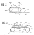
- Fig. 2 is an illustrative view of a coating apparatus of the present invention.
- a substrate 201 moves in the direction of arrow mark A to come into contact with a heat-soluble material feeder 207.
- the heat-soluble material feeder 207 comprises a heat roller 204, a remover 203 (in the illustrated case, an endless belt) and a block of heat-soluble material 205.
- the block of heat-soluble material 205 is melted by the heat of the heat roller 204 and laid on the substrate 201.
- the product is moved in the direction of arrow mark A, and when cooled, the substrate is peeled off by a removing unit comprising a removing roller 206 and the remover 203.
- a coating 202 of heat-solule material remains on the substrate 201.
- Fig. 3 is a construction view of a printer comprising the above coating apparatus additionally incorporated with a transfer unit (write-in unit).
- the printer includes a heat-soluble material supply unit and a removing unit comprising a heat roller 306, a remover 303, a heat-soluble material 305 and a removing roller 304, with which a coating 302 of heat-soluble material is formed on a substrate 301 of an endless belt form wound on belt rollers 307, 308.
- the transfer unit e.g., thermal head
- the part 311 is a coating of the transferred heat-soluble material, and 309 a platen.
- the part 312 is a coating of heat-soluble material remaining on the substrate side without being transferred.
- the coating of heat-soluble material thus remaining in a negative form again becomes a uniform film of heat-soluble materal by the coating unit (comprising a heat-soluble material supply part and the removing part).
- each part has been concretely shown, but the apparatuses of the present invention are not to be limited to them.
- Various methods of realizing the object of each part will come up to the mind of one skilled in the art of printing field.
- a coating thickness sensor may be provided, with which the heat-soluble material supply unit may be adjusted to perform coating thickness control and the like.
- the transfer unit write-in unit
- the printer may have a function of copying machine.
- a black heat-soluble material wax mixture [carbon powder (0.5 part by weight), carnauba wax (3.5 parts by weight), paraffin wax (3.5 parts by weight), melting point about 70 ⁇ 75 °C] was placed, which was heated to melt on a hot plate at about 100 °C.
- a remover PET sheet of 25 ⁇
- the product was cooled to room temperature (about 25 °C) to remove the remover as in Fig. b) in the state where the heat-soluble material was solid state.
- a shaded coating of heat-soluble material remained on the substrate.
- the coating thicknesses were about 1 ⁇ at a thin portion and about 3 ⁇ at a thick portion.
- Example 1 The operation to lay the remover on a hot plate in Example 1 was carried out with a fixer (for copying machine FP-1000 made by Matsushita Electric Industrial Co., Ltd.) at about 100 °C, followed by peeling off as shown in Fig. 1 b) to give a uniform coating of 5 ⁇ 8 ⁇ .
- a fixer for copying machine FP-1000 made by Matsushita Electric Industrial Co., Ltd.
- Example 1 When, in Example 1, a commercialized sheet already coated with an adhesive for laminate (TORAMI-FILM made by Tokyo Laminex) was used as a remover, there was obtained a uniform coating of heat-soluble material of 5 ⁇ 10 ⁇ .
- TORAMI-FILM made by Tokyo Laminex
- Example 3 Using a PET of 9 ⁇ , by the procedure of Example 3, a coating of heat-soluble material was prepared. The coating surface of the heat-soluble material was laid on a sheet of paper, and the laminate was inserted in the printer of a word processor (FW-20 made by Matsushita Electric Industrial Co., Ltd.). Excellent result was obtained.
- a word processor FW-20 made by Matsushita Electric Industrial Co., Ltd.
- Figs. 4 a) and b) are the views to illustrate a cleaning method of the present invention.
- the materials of an image-carrying substrate 403 include plastics, metal, non-liquid permeable paper, ceramics, etc.
- the image-carring substrate 403 is to carry an image-forming material 402 thereon.
- a heat-soluble material 404 is supplied as in Fig. 4 a), and a remover 405 is laid on the molten heat-soluble material. Then, the resulting product is cooled and the image-carrying substrate 403 is peeled off as in Fig. 4 b). At this time, the image-forming material 402 is moved to the remover together with the heat-soluble material 404 as in the drawing, and the image-carrying substrate is cleaned.
- the heat-soluble material includes, for example, wax, resins, or their mixture.
- a border line is drawn between the image-forming material and the heat-soluble material. However, if the image-forming material is the same one as the heat-soluble material or the one having the composition nearly similar to it, the two materials are cosolubilized to dissolve the border line.
- the remover includes many usable materials such as, for example, metal, resins, etc. Whether the image-forming material and the heat-soluble material attach to the remover or to the image-carring substrate depends on the adhesive force at the contact surface of each material, cohesion of the image-forming material and heat-soluble material, and further, whether to perform peeling off by curving the image-carring substance or by curving the remover.
- the remover and the image-carrying substrate are of the same materials and in the same surface conditions, and in case that the cohesion of the image-forming material and the heat-soluble material is larger than the adhesive force (where the image-forming material and the heat-soluble material are in solid state), the image-forming material and the heat-soluble material are separated from the curved side and remain on the flat side. If the cohesion of either the image-forming material or the heat-soluble material is smaller than the adhesive force (where any or either one of them is in liquid state), the image-forming material or the heat-soluble material is separated into two parts and attaches to both the remover and the image-carrying substrate.
- the sequence of cooling and then removing is in order to obtain an increased cleaning effect by increasing the cohesion of the image-forming material and heat-soluble material.
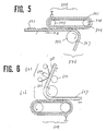
- Fig. 5 is a construction view of a cleaning apparatus of the present invention.
- An image-carrying substrate 507 carrying an image-forming material 502 moves in the direction of the arrow mark A to come into contact with a heat-soluble material supply unit 505.
- the heat-soluble material supply unit comprises a heat roller 503, a roller 508, a remover 501 (in the illustrated case, an endless belt) and a heat-soluble material 504.
- the heat-soluble material 504 is cleaned and removed, and also supplied.
- the part to be cleaned and removed is not illustrated, but in practice it is provided.
- the heat-soluble material 504 is molten by the heat-roller 503 and laid on the image-carrying substrate 507. Under this condition, the resulting product moves in the direction of arrow mark A, and after cooling, the substrate is peeled off by a removing unit 506 comrising a removing roller 502. At this time, the image-forming material attaches to and is carried by the heat-soluble material which has been solidified or elevated in cohesion. In this way, the image-forming material on the image-carrying substrate can be readily cleaned. Therefore, if an image is formed by placing a heat-soluble material on the cleaned image-carrying substrate again by heat transfer or the like, a display method as described hereinafter can be obtained.
- Fig. 6 is a construction view of a display apparatus for displaying information and data by carrying out writing and cleaning.
- An image-carrying substrate 607 is brought into contact with a heat-soluble material supply unit 605 similar to that shown in Fig. 5, cleaned by a removing unit 606, and on it again new information and data are written in (image-forming material is laid) with a transfer unit (write-in unit) 601.
- the transfer unit 601 comprises a thermal head 602, a thermal ink-transfer ribbon 603 and a platen 604.
- the part 608 is a newly laid image-forming material.
- the thermal ink-transfer ribbon 603 may be made by using the aforementioned coating method (coating method as shown in Fig. 2). In this case, the running cost is reduced.
- the image-carrying substrate may be endless or cut sheet form.
- a cut sheet it can be utilized as erasable paper.
- plastic material especially a polyethylene terephthalate sheet
- a releasing layer of silicon resin or the like which has good releasing property, is formed on the surface of such sheet, removal of the image forming material is assured, and clean surface condition is easily maintained for a long duration.
- a printing method which comprises repeating steps of placing an image-forming material on an image-carrying substrate, transferring the image-forming material to a material to be printed, and cleaning the image-forming material which remained not-transferred.
- the suprior point of this printing method to the ordinary printing method of thermal transfer system is that the beautiful printing can be made on rough paper, if an elastic image-forming material substrate (blanket) is used.
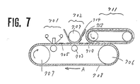
- Fig. 7 is a construction view of a printer.
- An endless image-carrying substrate 708 (blanket) is run in the direction of arrow mark A in the drawing with a roller 707 and a removing roller 706.
- a first transfer unit (write-in unit) 701 an image 705 by the image-forming material is made, which is transferred to a material to be printed 704 by a second transfer unit 702.
- the part 712 is a transferred image.
- the second transfer unit 702 comprises a pressure roller 703 and a heat roller 709.
- the image-forming material 710 which remained without being transferred is cleaned by a heat-soluble material supply unit 711 and the removing roller 706.
- the transfer unit write-in unit
- the printer may have a function of copying machine.
- Example 5 instead of making the image on the image-carrying substrate by thermal transfer, the image was made by copying a magazine with a copying machine (PP-2520 made by Matsushita Electric Industrial Co., Ltd.). That is to say, an OHP was made.
- PP-2520 made by Matsushita Electric Industrial Co., Ltd.
- Example 5 a commercialized sheet coated with an adhesive for laminate (article name: TORAMI-FILM made by Tokyo Laminex) was used as a remover, by which good cleaning could be performed as in Example 5.
- an adhesive for laminate article name: TORAMI-FILM made by Tokyo Laminex
- Example 5 Using a 25 ⁇ PET, the operation was made in the same manner as in Example 5 to obtain an image-carrying substrate by thermal transfer.
- the resulting image on the image-forming material (heat-soluble ink) side was laid on paper (smoothness, 40 seconds) and passed through a space between the heat roller (metal) at about 105°C and the pressure roller (silicon rubber). Although blur was formed, clear printing could be obtained. At that time, the image-forming material partly remained on the image-carrying substrate, without being fully transferred.
- a commercialized thermal ink-transfer ribbon (made by Fuji Kagakushi Kabushiki Kaisha; melting point of ink about 70°C) was laid as a remover, and the layer was heated and squeezed with a roller to expel foams. The resulting product was cooled. With the thermal ink-transfer ribbon side kept flat and the image-carrying substrate curved, peeling was performed, by which the image-carrying substrate was cleaned.
Landscapes
- Physics & Mathematics (AREA)
- Optics & Photonics (AREA)
- Thermal Transfer Or Thermal Recording In General (AREA)
- Application Of Or Painting With Fluid Materials (AREA)
- Accessory Devices And Overall Control Thereof (AREA)
Applications Claiming Priority (4)
| Application Number | Priority Date | Filing Date | Title |
|---|---|---|---|
| JP128946/88 | 1988-05-26 | ||
| JP12894688A JP2958772B2 (ja) | 1988-05-26 | 1988-05-26 | クリーニング方法とクリーニング装置並びに表示方法と表示装置 |
| JP63133262A JP2591065B2 (ja) | 1988-05-31 | 1988-05-31 | 製膜方法と製膜装置並びに印刷方法と印刷装置 |
| JP133262/88 | 1988-05-31 |
Publications (3)
| Publication Number | Publication Date |
|---|---|
| EP0343951A2 true EP0343951A2 (de) | 1989-11-29 |
| EP0343951A3 EP0343951A3 (de) | 1991-03-20 |
| EP0343951B1 EP0343951B1 (de) | 1995-10-18 |
Family
ID=26464506
Family Applications (1)
| Application Number | Title | Priority Date | Filing Date |
|---|---|---|---|
| EP89305242A Expired - Lifetime EP0343951B1 (de) | 1988-05-26 | 1989-05-24 | Beschichtungs- und Reinigungsverfahren bei dem ein thermoplastisches Material benutzt wird |
Country Status (3)
| Country | Link |
|---|---|
| US (1) | US5006189A (de) |
| EP (1) | EP0343951B1 (de) |
| DE (1) | DE68924555T2 (de) |
Cited By (1)
| Publication number | Priority date | Publication date | Assignee | Title |
|---|---|---|---|---|
| EP0635379A1 (de) * | 1993-07-22 | 1995-01-25 | Ricoh Company, Ltd | Bildtragendes Element und Verfahren zu seiner Wiederverwertung |
Families Citing this family (17)
| Publication number | Priority date | Publication date | Assignee | Title |
|---|---|---|---|---|
| US5353108A (en) * | 1990-07-05 | 1994-10-04 | Matsushita Electric Industrial Co., Ltd. | Apparatus for cleaning printed paper |
| JPH06250569A (ja) * | 1993-02-26 | 1994-09-09 | Ricoh Co Ltd | 画像支持体の再生方法 |
| JP3273874B2 (ja) * | 1994-02-25 | 2002-04-15 | 株式会社リコー | 被記録材の再生方法および再生装置 |
| JP2764067B2 (ja) * | 1994-05-13 | 1998-06-11 | 株式会社リコー | 像保持体からの像形成物質除去方法及びその装置 |
| US5729349A (en) * | 1995-02-10 | 1998-03-17 | Ricoh Company, Ltd. | Method and device for determining fiber orientation of paper, and apparatus for removing image forming substance from paper |
| US5835837A (en) * | 1995-04-06 | 1998-11-10 | Ricoh Company, Ltd. | Apparatus for removing image forming substance from image holding member |
| EP0745490B1 (de) * | 1995-05-31 | 2000-10-11 | Kodak Polychrome Graphics LLC | Verfahren zur Herstellung eines Bildaufzeichnungselements |
| US5935363A (en) * | 1996-07-11 | 1999-08-10 | Hollister Incorporated | Process for making contoured hydrocolloid-containing adhesive dressings |
| JP3441935B2 (ja) * | 1996-10-07 | 2003-09-02 | 株式会社リコー | 像保持体の再生方法及びその装置 |
| US6128464A (en) * | 1997-04-10 | 2000-10-03 | Minolta Co., Ltd. | Apparatus for removing printing material from a recording member on which an image is recorded by the printing material |
| US6076218A (en) * | 1997-04-10 | 2000-06-20 | Minolta Co., Ltd. | Apparatus for removing printing material |
| JP3567714B2 (ja) * | 1998-01-20 | 2004-09-22 | 富士ゼロックス株式会社 | 画像形成材料除去装置 |
| JPH11237817A (ja) * | 1998-02-20 | 1999-08-31 | Minolta Co Ltd | 印字材料の除去装置 |
| US6913860B2 (en) * | 2001-07-31 | 2005-07-05 | Ricoh Company, Ltd. | Image forming material, method and device for removing images, and image forming process and apparatus |
| ATE345784T1 (de) * | 2002-01-25 | 2006-12-15 | Lohmann Therapie Syst Lts | Verfahren und gerät zum herstellen von bahnförmigen materialien |
| JP4740296B2 (ja) * | 2008-08-28 | 2011-08-03 | リンテック株式会社 | シート剥離装置及び剥離方法 |
| JP2019014246A (ja) * | 2017-07-04 | 2019-01-31 | キヤノン株式会社 | インクジェット記録方法及びインクジェット記録装置 |
Family Cites Families (4)
| Publication number | Priority date | Publication date | Assignee | Title |
|---|---|---|---|---|
| US1960647A (en) * | 1930-10-08 | 1934-05-29 | George E Pelton | Method of and apparatus for producing ink transfer members |
| GB2044473A (en) * | 1979-03-23 | 1980-10-15 | Minnesota Mining & Mfg | Thermographic imaging sheet |
| US4744851A (en) * | 1985-01-24 | 1988-05-17 | The Goodyear Tire & Rubber Company | Method of producing rubber sheets having clean areas |
| US4746389A (en) * | 1987-08-04 | 1988-05-24 | United Technologies Corporation | Method for producing a clean, highly conductive surface for mating composite articles |
-
1989
- 1989-05-24 EP EP89305242A patent/EP0343951B1/de not_active Expired - Lifetime
- 1989-05-24 DE DE68924555T patent/DE68924555T2/de not_active Expired - Fee Related
- 1989-05-26 US US07/357,597 patent/US5006189A/en not_active Expired - Lifetime
Cited By (1)
| Publication number | Priority date | Publication date | Assignee | Title |
|---|---|---|---|---|
| EP0635379A1 (de) * | 1993-07-22 | 1995-01-25 | Ricoh Company, Ltd | Bildtragendes Element und Verfahren zu seiner Wiederverwertung |
Also Published As
| Publication number | Publication date |
|---|---|
| DE68924555D1 (de) | 1995-11-23 |
| EP0343951B1 (de) | 1995-10-18 |
| DE68924555T2 (de) | 1996-05-15 |
| EP0343951A3 (de) | 1991-03-20 |
| US5006189A (en) | 1991-04-09 |
Similar Documents
| Publication | Publication Date | Title |
|---|---|---|
| EP0343951A2 (de) | Beschichtungs- und Reinigungsverfahren bei dem ein thermoplastisches Material benutzt wird | |
| JP2958772B2 (ja) | クリーニング方法とクリーニング装置並びに表示方法と表示装置 | |
| JP2778331B2 (ja) | インクジェット記録装置 | |
| US20010010851A1 (en) | Optical disk, method of forming image on optical disk, image forming apparatus and adhesive layer transfer sheet | |
| JP2762751B2 (ja) | 画像保護フィルム | |
| EP0378291B1 (de) | Aufzeichnungsvorrichtung | |
| EP0042954A2 (de) | Band für korrigierbaren Thermotransferdruck | |
| JPS6151391A (ja) | 熱転写記録媒体と熱転写装置 | |
| JPH0120992B2 (de) | ||
| JPS63128987A (ja) | 乾式転写材の基本シ−ト | |
| JP2628639B2 (ja) | インスタントレタリング用乾式転写シートの製造方法 | |
| EP0518621B1 (de) | Verfahren zum Behandeln bedruckter Substrate | |
| JPH0639190B2 (ja) | Ohpフイルム作成シ−ト | |
| KR20050002839A (ko) | 열전사 기록 매체 및 인화물 | |
| EP0499195B1 (de) | Wärmeempfindliches Übertragungsaufzeichnungsmaterial | |
| US5367322A (en) | Thermal recording apparatus | |
| JP2000190636A (ja) | 間接転写装置 | |
| JPH1029331A (ja) | 熱転写記録装置 | |
| JP2570699B2 (ja) | 熱転写インクリボンの多数回使用法 | |
| JPS629991A (ja) | 熱転写記録用インクリボンとこのインクリボンを用いた記録装置 | |
| JPS6334169A (ja) | 記録方法 | |
| JPH01301340A (ja) | 製膜方法と製膜装置並びに印刷方法と印刷装置 | |
| JPH1191197A (ja) | 電子写真方式通帳印字/発行装置及びその通帳 | |
| JPH01216863A (ja) | 画像出力方法 | |
| JPH05318912A (ja) | 感熱記録紙及びその製造法 |
Legal Events
| Date | Code | Title | Description |
|---|---|---|---|
| PUAI | Public reference made under article 153(3) epc to a published international application that has entered the european phase |
Free format text: ORIGINAL CODE: 0009012 |
|
| AK | Designated contracting states |
Kind code of ref document: A2 Designated state(s): DE FR GB NL |
|
| PUAL | Search report despatched |
Free format text: ORIGINAL CODE: 0009013 |
|
| AK | Designated contracting states |
Kind code of ref document: A3 Designated state(s): DE FR GB NL |
|
| 17P | Request for examination filed |
Effective date: 19910917 |
|
| 17Q | First examination report despatched |
Effective date: 19930921 |
|
| GRAA | (expected) grant |
Free format text: ORIGINAL CODE: 0009210 |
|
| AK | Designated contracting states |
Kind code of ref document: B1 Designated state(s): DE FR GB NL |
|
| REF | Corresponds to: |
Ref document number: 68924555 Country of ref document: DE Date of ref document: 19951123 |
|
| ET | Fr: translation filed | ||
| PLBE | No opposition filed within time limit |
Free format text: ORIGINAL CODE: 0009261 |
|
| STAA | Information on the status of an ep patent application or granted ep patent |
Free format text: STATUS: NO OPPOSITION FILED WITHIN TIME LIMIT |
|
| 26N | No opposition filed | ||
| PGFP | Annual fee paid to national office [announced via postgrant information from national office to epo] |
Ref country code: NL Payment date: 19970529 Year of fee payment: 9 |
|
| PG25 | Lapsed in a contracting state [announced via postgrant information from national office to epo] |
Ref country code: NL Free format text: LAPSE BECAUSE OF NON-PAYMENT OF DUE FEES Effective date: 19981201 |
|
| NLV4 | Nl: lapsed or anulled due to non-payment of the annual fee |
Effective date: 19981201 |
|
| REG | Reference to a national code |
Ref country code: GB Ref legal event code: IF02 |
|
| REG | Reference to a national code |
Ref country code: GB Ref legal event code: 746 Effective date: 20031002 |
|
| REG | Reference to a national code |
Ref country code: FR Ref legal event code: D6 |
|
| PGFP | Annual fee paid to national office [announced via postgrant information from national office to epo] |
Ref country code: DE Payment date: 20070517 Year of fee payment: 19 |
|
| PGFP | Annual fee paid to national office [announced via postgrant information from national office to epo] |
Ref country code: GB Payment date: 20070523 Year of fee payment: 19 |
|
| PGFP | Annual fee paid to national office [announced via postgrant information from national office to epo] |
Ref country code: FR Payment date: 20070510 Year of fee payment: 19 |
|
| GBPC | Gb: european patent ceased through non-payment of renewal fee |
Effective date: 20080524 |
|
| REG | Reference to a national code |
Ref country code: FR Ref legal event code: ST Effective date: 20090119 |
|
| PG25 | Lapsed in a contracting state [announced via postgrant information from national office to epo] |
Ref country code: FR Free format text: LAPSE BECAUSE OF NON-PAYMENT OF DUE FEES Effective date: 20080602 Ref country code: DE Free format text: LAPSE BECAUSE OF NON-PAYMENT OF DUE FEES Effective date: 20081202 |
|
| PG25 | Lapsed in a contracting state [announced via postgrant information from national office to epo] |
Ref country code: GB Free format text: LAPSE BECAUSE OF NON-PAYMENT OF DUE FEES Effective date: 20080524 |