EP0343325B1 - Dampfdruckkochtopf/Kochstellen-System - Google Patents
Dampfdruckkochtopf/Kochstellen-System Download PDFInfo
- Publication number
- EP0343325B1 EP0343325B1 EP89104046A EP89104046A EP0343325B1 EP 0343325 B1 EP0343325 B1 EP 0343325B1 EP 89104046 A EP89104046 A EP 89104046A EP 89104046 A EP89104046 A EP 89104046A EP 0343325 B1 EP0343325 B1 EP 0343325B1
- Authority
- EP
- European Patent Office
- Prior art keywords
- pressure
- pressure cooker
- cooker
- hob
- cooking device
- Prior art date
- Legal status (The legal status is an assumption and is not a legal conclusion. Google has not performed a legal analysis and makes no representation as to the accuracy of the status listed.)
- Expired - Lifetime
Links
- 238000010411 cooking Methods 0.000 title abstract description 9
- 235000014676 Phragmites communis Nutrition 0.000 claims description 10
- 230000006698 induction Effects 0.000 description 6
- BGPVFRJUHWVFKM-UHFFFAOYSA-N N1=C2C=CC=CC2=[N+]([O-])C1(CC1)CCC21N=C1C=CC=CC1=[N+]2[O-] Chemical compound N1=C2C=CC=CC2=[N+]([O-])C1(CC1)CCC21N=C1C=CC=CC1=[N+]2[O-] BGPVFRJUHWVFKM-UHFFFAOYSA-N 0.000 description 2
- 238000010586 diagram Methods 0.000 description 1
- 238000000034 method Methods 0.000 description 1
- 230000001105 regulatory effect Effects 0.000 description 1
- 230000000007 visual effect Effects 0.000 description 1
Images

Classifications
-
- A—HUMAN NECESSITIES
- A47—FURNITURE; DOMESTIC ARTICLES OR APPLIANCES; COFFEE MILLS; SPICE MILLS; SUCTION CLEANERS IN GENERAL
- A47J—KITCHEN EQUIPMENT; COFFEE MILLS; SPICE MILLS; APPARATUS FOR MAKING BEVERAGES
- A47J27/00—Cooking-vessels
- A47J27/08—Pressure-cookers; Lids or locking devices specially adapted therefor
- A47J27/0802—Control mechanisms for pressure-cookers
-
- A—HUMAN NECESSITIES
- A47—FURNITURE; DOMESTIC ARTICLES OR APPLIANCES; COFFEE MILLS; SPICE MILLS; SUCTION CLEANERS IN GENERAL
- A47J—KITCHEN EQUIPMENT; COFFEE MILLS; SPICE MILLS; APPARATUS FOR MAKING BEVERAGES
- A47J36/00—Parts, details or accessories of cooking-vessels
- A47J36/32—Time-controlled igniting mechanisms or alarm devices
Definitions
- the invention relates to a steam pressure / hob system with the features of the first part of claim 1.
- a "cooking regulator” is provided with a magnet which acts on a reed relay.
- This "cooking regulator” is used for manual setting of different cooking levels, so it specifies the "target pressure”.
- a steam pressure indicator shows the "actual pressure”.
- the invention is based on the object of developing the previously known pressure cooker / hotplate system in such a way that the pressure in the pressure cooker is regulated automatically.
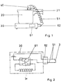
- Fig. 1 shows a pressure cooker 20, which stands on a hotplate 30, preferably an induction hotplate.
- the pressure cooker 20 is provided with a lid handle 21, which receives a pressure display, not shown in the drawing.
- An adapter 40 is placed on the lid handle 21 and interrogates the pressure display in the lid handle 21.
- This adapter 40 is connected via a cable 51 via a timer 62 to the induction hob 30, which is provided with a relay 61.
- Fig. 2 illustrates the connection.
- a reed relay 3 arranged in the adapter 40, a timing element 62 and the control circuit of a relay 61, the working circuit of which switches the induction coil of the hotplate 30, are connected in series in a circuit guided by the cable 51.
- the reed relay 3 which is arranged in the adapter 40 on the pressure cooker 20, drops out.
- the circuit is interrupted, which leads to a drop in the contacts of the relay 61.
- the induction coil of the induction hotplate 30 is no longer supplied with voltage, the pressure cooker cools down.
- the pressure in the pressure cooker will drop again accordingly, which leads to actuation of the reed relay 3, whereupon the control circuit is switched through again is and the relay 61 picks up again, so that the induction coil in the hotplate 30 is supplied with energy again.
- the circuit thus forms a closed control loop which ensures that the pressure in the pressure cooker is kept constant.
- the timer 62 is preferably designed to be adjustable and serves to carry out the cooking process after a first preselected time period and to end after a second predefined time period.
- the pressure cooker / hotplate system proposed here makes it possible to keep the pressure in the pressure cooker constantly in a desired range without the need for user intervention.
- Fig. 3 shows a longitudinal sectional view through the adapter 40 placed on the lid handle 21 of the pressure cooker 20.
- This adapter 40 consists of a housing 1 and a base 2 placed on the lid handle 21, the housing 1 and base 2 via a screw 12 (cf. Fig. 4) are interconnected.
- the housing 1 accommodates an encapsulated reed relay 3 and a display housing consisting of a lower part 8 and an upper part 9.
- the lower part 8 of the display housing receives a magnet 5 and an adjusting washer 4, whereby the magnet 5 can be adjusted via an adjusting spindle 7 seated on the upper part 9 of the display housing so that the reed relay 3 at a preselectable pressure in the Pressure cooker appeals.
- FIG. 4 The cross-sectional view of Fig. 4 shows that the means 40 seated on the lid handle 21 for querying the respective pressure in the pressure cooker is provided with a connection socket 13 which serves to receive a plug to which a two-wire cable 51 is connected to the hotplate 30 leads.
- the basic idea of the invention of using the pressure prevailing in the saucepan to control the supply of energy to the hotplate can also be realized by a different design of the means for detecting the pressure, any type of pressure sensor being considered.
- the embodiment shown here as a particularly preferred embodiment has the advantage that the tried and tested roof pressure cookers can be equipped or retrofitted with a pressure indicator integrated in the lid handle.
Landscapes
- Engineering & Computer Science (AREA)
- Food Science & Technology (AREA)
- Cookers (AREA)
- General Preparation And Processing Of Foods (AREA)
Description
- Die Erfindung betrifft ein Dampfdruck/Kochstellen-System mit den Merkmalen des ersten Teiles des Anspruchs 1.
- Bei einem solchen aus der DE 35 10 542 A1 bekannten System ist ein "Kochregler" mit einem Magneten versehen, der auf ein Reed-Relais wirkt. Dieser "Kochregler" dient zur manuellen Einstellung verschiedener Kochstufen, er gibt also den "Solldruck" an. Ein Dampfdruckanzeiger zeigt den "Ist-Druck" an.
- Der Erfindung liegt die Aufgabe zugrunde, das vorbekannte Dampfdruckkochtopf/Kochstellen-System derart weiterzubilden, daß eine automatische Regelung des Druck in dem Dampfdruckkochtopf erfolgt.
- Erfindungsgemäß wird diese Aufgabe durch die im zweiten Teil des Anspruchs 1 angegebenen Merkmale gelöst. Der einzige Unteranspruch gibt eine vorteilhafte Ausgestaltung des Systems an.
- Die Erfindung wird im folgenden anhand einer Zeichnung erläutert. Dabei zeigt:
- Fig. 1
- eine schematische Darstellung eines Dampfdruckkochtopfes und einer Kochstelle,
- Fig. 2
- eine die Verschaltung verdeutlichende Darstellung,
- Fig. 3
- eine Darstellung des auf den Deckelgriff aufgesetzten Adapters in einer Längsschnittdarstellung, und
- Fig. 4
- eine Darstellung des Regeladapters in einer Querschnittsdarstellung.
- Fig. 1 zeigt einen Dampfdruckkochtopf 20, der auf einer Kochstelle 30, vorzugsweise einer Induktions-Kochstelle, steht. Der Dampfdruckkochtopf 20 ist mit einem Deckelgriff 21 versehen, der eine - zeichnerisch nicht dargestellte - Druckanzeige aufnimmt. Auf den Deckelgriff 21 ist ein Adapter 40 aufgesetzt, der die Druckanzeige in dem Deckelgriff 21 abfragt. Dieser Adapter 40 ist über ein Kabel 51 über ein Zeitglied 62 mit der Induktions-Kochstelle 30 verbunden, die mit einem Relais 61 versehen ist.
- Fig. 2 verdeutlicht die Verschaltung. Ein in dem Adapter 40 angeordnetes Reed-Relais 3, ein Zeitglied 62 und der Steuerkreis eines Relais 61, dessen Arbeitskreis die Induktionsspule der Kochstelle 30 schaltet, liegen in einem durch das Kabel 51 geführten Stromkreis in Reihe. Bei Überschreiten eines bestimmten Drucks fällt das Reed-Relais 3, das in dem Adapter 40 auf dem Dampfdruckkochtopf 20 angeordnet ist, ab. Der Stromkreis wird unterbrochen, was zu einem Abfall der Arbeitskontakte des Relais 61 führt. Die Induktionsspule der Induktions-Kochstelle 30 wird nicht mehr mit Spannung versorgt, der Dampfdruckkochtopf kühlt ab. Der Druck in dem Dampfdruckkochtopf wird entsprechend wieder abfallen, was zu einem Betätigen des Reed-Relais 3 führt, woraufhin der Steuerstromkreis wieder durchgeschaltet ist und das Relais 61 wieder anzieht, so daß die Induktionsspule in der Kochstelle 30 wieder mit Energie versorgt wird. Die Schaltung bildet so einen geschlossenen Regelkreis, der das Konstanthalten des Drucks in dem Dampfdruckkochtopf sicherstellt.
- Das Zeitglied 62 ist vorzugsweise einstellbar ausgebildet und dient dazu, den Kochvorgang nach einer ersten vorgewählten Zeitdauer durchzuführen und nach einer zweiten vorgegebenen Zeitdauer zu beenden. Das hier vorgeschlagene Dampfdruckkochtopf/Kochstellen-System ermöglicht es also, den Druck in dem Dampfdruckkochtopf ständig in einem gewünschten bereich zu halten, ohne daß es eines Eingriffs durch den Benutzer bedarf.
- Fig. 3 zeigt eine Längsschnittdarstellung durch den auf dem Deckelgriff 21 des Dampfdruckkochtopfes 20 aufgesetzten Adapters 40. Dieser Adapter 40 besteht aus einem Gehäuse 1 und einem auf den Deckelgriff 21 aufgesetzten Sockel 2, wobei Gehäuse 1 und Sockel 2 über eine Schraube 12 (vgl. Fig. 4) miteinander verbunden sind. Das Gehäuse 1 nimmt ein gekapseltes Reed-Relais 3 und ein aus einem Unterteil 8 und einem Oberteil 9 bestehendes Anzeigegehäuse auf. Das Unterteil 8 des Anzeigegehäuses nimmt einen Magneten 5 und eine zur Justierung dienende Gewindescheibe 4 auf, wodurch der Magnet 5 über eine auf dem Oberteil 9 des Anzeigegehäuses sitzende Justierspindel 7 so eingestellt werden kann, daß das Reed-Relais 3 bei einem vorwählbaren Druck in dem Dampfdruckkochtopf anspricht.
- Bei der hier als bevorzugte Ausgestaltung vorgeschlagenen Ausbildung des Mittels zum Erfassen einer dem jeweiligen Innendruck des Dampfdruck-kochtopfs entsprechenden Information wird also ausgenutzt, daß bei üblichen Dampfdruckkochtöpfen bereits ein mechanischer Druckanzeiger vorgesehen ist, der sich mit steigendem Druck hebt. Durch die hier vorgeschlagene Anordnung wird die Höhe des Druckanzeigers erfaßt, wobei bei einer bestimmten Höhe das Reed-Relais 3 anspricht.
- Die optische Kontrolle des jeweiligen Drucks in dem Kochtopf bleibt durch die Sichtbarkeit des Oberteils 9 des Anzeigegehäuses möglich.
- Die Querschnittsdarstellung von Fig. 4 zeigt, daß das auf dem Deckelgriff 21 aufsitzende Mittel 40 zum Abfragen des jeweiligen Drucks in dem Dampfdruckkochtopf mit einer Anschlußbuchse 13 versehen ist, die zur Aufnahme eines Steckers dient, an den ein zweiadriges Kabel 51 angeschlossen ist, das zu der Kochstelle 30 führt.
- Der Grundgedanke der Erfindung, den jeweils in dem Kochtopf herrschenden Druck zum Steuern der Energiezufuhr zu der Kochstelle zu nutzen, kann auch durch eine andere Ausbildung der Mittel zum Erfassen des Drucks verwirklicht werden, wobei jede Art von Drucksensoren in Betracht kommen. Die hier als besonders bevorzugte Ausbildung dargestellte Ausführungsform hat jedoch den Vorteil, daß die bewährten Dachdruckkochtöpfe mit einer in den Deckelgriff integrierten Druckanzeige entsprechend aus- oder nachgerüstet werden können.
- Die in der vorstehenden Beschreibung, in der Zeichnung sowie in den Ansprüchen offenbarten Merkmale der Erfindung können sowohl einzeln als auch in beliebiger Kombination für die Verwirklichung der Erfindung in ihren verschiedenen Ausführungsformen wesentlich sein.
Claims (2)
- Dampfdruckkochtopf/Kochstellen-System mit einer Kochstelle mit geringer thermischer Trägheit, bei dem der Dampfdruckkochtopfs (20) mit einem in dessen Deckelgriff (21) integrierten, sich mit steigendem Druck hebenden Druckanzeiger, Mitteln zum Erfassen einer dem jeweiligen Innendruck entsprechenden Information und Mitteln zum Übertragen dieser Information zu der Kochstelle (30) versehen ist und die Kochstelle (30) Mittel zum Steuern der Energiezufuhr in Abhängigkeit von dem jeweiligen Innendruck des Dampfdruckkochtopfs (20) aufweist,
dadurch gekennzeichnet, daß das Mittel zum Erfassen der dem jeweiligen Innendruck des Dampfdruckkochtopfs entsprechenden Information ein Reed-Relais (3) ist, auf das ein von dem Druckanzeiger mechanisch relativ zu diesem verschobener Magnet (5) wirkt. - Dampfdruckkochtopf/Kochstellen-System nach Anspruch 1, dadurch gekennzeichnet, daß das Mittel zum Übertragen der dem jeweiligen Innendruck des Dampfkochtopfs (20) entsprechenden Information ein diesen mit der Kochstelle (30) verbindendes Kabel (51) ist, zwischen dessen beiden Adern das Reed-Relais liegt, und das Mittel zum Steuern der Energiezufuhr zu der Kochstelle (30) ein Relais (61) aufweist, in dessen Steuerkreis das Reed-Relais liegt.
Priority Applications (1)
| Application Number | Priority Date | Filing Date | Title |
|---|---|---|---|
| AT89104046T ATE83140T1 (de) | 1988-05-27 | 1989-03-08 | Dampfdruckkochtopf/kochstellen-system. |
Applications Claiming Priority (2)
| Application Number | Priority Date | Filing Date | Title |
|---|---|---|---|
| DE3818037 | 1988-05-27 | ||
| DE3818037 | 1988-05-27 |
Publications (3)
| Publication Number | Publication Date |
|---|---|
| EP0343325A2 EP0343325A2 (de) | 1989-11-29 |
| EP0343325A3 EP0343325A3 (en) | 1990-03-14 |
| EP0343325B1 true EP0343325B1 (de) | 1992-12-09 |
Family
ID=6355251
Family Applications (1)
| Application Number | Title | Priority Date | Filing Date |
|---|---|---|---|
| EP89104046A Expired - Lifetime EP0343325B1 (de) | 1988-05-27 | 1989-03-08 | Dampfdruckkochtopf/Kochstellen-System |
Country Status (4)
| Country | Link |
|---|---|
| EP (1) | EP0343325B1 (de) |
| AT (1) | ATE83140T1 (de) |
| DE (1) | DE58902936D1 (de) |
| ES (1) | ES2037296T3 (de) |
Families Citing this family (8)
| Publication number | Priority date | Publication date | Assignee | Title |
|---|---|---|---|---|
| CH688419C1 (de) * | 1992-09-01 | 1999-09-30 | Heinrich Kuhn Metallwarenfabrik Ag | Sicherheitsventil fuer einen dampfdruckkochtopf. |
| ES2078847B1 (es) * | 1993-07-13 | 1996-08-01 | Fagor S Coop Ltda | Olla a presion con base calefactora y sistema de regulacion. |
| GB9501638D0 (en) * | 1995-01-27 | 1995-03-15 | Prestige Group Uk Plc | Pressure cooker control arrangement |
| FR2735673B1 (fr) * | 1995-06-21 | 1997-11-07 | Pesenti Yvan | Autocuiseur electrique a pression de vapeur regulee par pilotage de son chauffage |
| AT402783B (de) * | 1996-03-18 | 1997-08-25 | Erich Dipl Ing Harasko | Automatik-druckkochtopf |
| DE19729662A1 (de) * | 1997-07-11 | 1999-01-14 | Ego Elektro Geraetebau Gmbh | Informations-Übertragungssystem |
| EP1884179B1 (de) * | 2006-07-25 | 2016-05-04 | WMF Group GmbH | Dampfkochtopf |
| CN109124322B (zh) * | 2017-06-16 | 2021-09-21 | 佛山市顺德区美的电热电器制造有限公司 | 压力锅的控制方法 |
Family Cites Families (5)
| Publication number | Priority date | Publication date | Assignee | Title |
|---|---|---|---|---|
| US2495603A (en) * | 1947-06-30 | 1950-01-24 | Swartzbaugh Mfg Company | Automatically controlled electric pressure cooker |
| DE2932039A1 (de) * | 1979-08-07 | 1981-02-26 | Wmf Wuerttemberg Metallwaren | Einrichtung zum steuern der kochbzw. garzeit an kochgefaessen |
| DE3004088A1 (de) * | 1980-02-05 | 1981-08-13 | Alfons Weiss Kg, Fabrik Feinwerktechn. Erzeugnisse, 7209 Gosheim | Einrichtung zum ueberwachen des garprozesses von kochgut zur verwendung bei einem kochtopf, insbesondere dampfkochtopf |
| DE3026620A1 (de) * | 1980-07-14 | 1982-02-04 | Braun & Kemmler | Kochreguliereinrichtung |
| DE3510542A1 (de) * | 1985-03-22 | 1986-10-02 | Silit-Werke Gmbh & Co Kg, 7940 Riedlingen | Vorrichtung zur steuerung des garprozesses in einem dampfdruckkochtopf |
-
1989
- 1989-03-08 AT AT89104046T patent/ATE83140T1/de not_active IP Right Cessation
- 1989-03-08 DE DE8989104046T patent/DE58902936D1/de not_active Expired - Fee Related
- 1989-03-08 EP EP89104046A patent/EP0343325B1/de not_active Expired - Lifetime
- 1989-03-08 ES ES198989104046T patent/ES2037296T3/es not_active Expired - Lifetime
Also Published As
| Publication number | Publication date |
|---|---|
| DE58902936D1 (de) | 1993-01-21 |
| ES2037296T3 (es) | 1993-06-16 |
| EP0343325A3 (en) | 1990-03-14 |
| EP0343325A2 (de) | 1989-11-29 |
| ATE83140T1 (de) | 1992-12-15 |
Similar Documents
| Publication | Publication Date | Title |
|---|---|---|
| DE69507147T2 (de) | Verbesserte Kaffeemaschine | |
| DE68922030T2 (de) | Apparat und Verfahren zur Relaisteuerung. | |
| DE3508003A1 (de) | Steuereinrichtung fuer ein fritiergeraet | |
| DE2932039A1 (de) | Einrichtung zum steuern der kochbzw. garzeit an kochgefaessen | |
| EP0343325B1 (de) | Dampfdruckkochtopf/Kochstellen-System | |
| DE3624664A1 (de) | Schnittstelle zwischen motorsteuerung und gluehanlage eines dieselmotors | |
| DE102010054979A1 (de) | Ventilanordnung und Verfahren zum Betätigen eines Ventils | |
| DE3541277A1 (de) | Steuervorrichtung fuer einen druckmaschinenantriebsmotor oder dergleichen | |
| DE69007511T2 (de) | Vorrichtung in einem Kochherd oder in einer Wärmeplatte für Kochzwecke. | |
| DE29700291U1 (de) | Kaffeemaschine | |
| DE3026620A1 (de) | Kochreguliereinrichtung | |
| DE69704383T2 (de) | Einrichtung zum Schliessen und automatischen Öffnen des Deckels eines Kochgeräts, insbesondere eines Grills und dergleiches | |
| EP0780081B1 (de) | Verfahren zur automatischen Regelung von beheizbaren Kochstellen | |
| EP0575967B1 (de) | Schlauchkennung | |
| EP0173820A1 (de) | Versenkbarer Drehknebel | |
| DE4309121A1 (de) | Regelvorrichtung für ein Heizkörperventil | |
| DE3446149C2 (de) | ||
| EP0725667A1 (de) | Verfahren und vorrichtung zur regelung und steuerung einer destillations- oder kondensationsapparatur | |
| EP0033056B1 (de) | Elektronisches Regelgerät | |
| DE19851029C2 (de) | Verfahren zum Anpassen des Grenzwertes der Betriebstemperatur einer Glas-/Glaskeramikkochfläche und Vorrichtung zur Durchführung des Verfahrens | |
| DE2462225A1 (de) | Heizungseinrichtung fuer eine vorrichtung zum herstellen von pfannkuchen | |
| DE2112121A1 (de) | Vorrichtung zur Regelung des Fluessigkeitsstandes in einem Behaelter | |
| EP0971220A2 (de) | Vorrichtung zur Erfassung der Wicklungstemperatur eines über eine Steuerschaltung betriebenen Elektromotors | |
| DE837979C (de) | Einrichtung zur Kontrolle und gegebenenfalls selbsttaetigen Regulierung des Verkochungsvorganges bei der Zuckergewinnung | |
| DE732163C (de) | Stufenspannungswandleranordnung fuer hohe Spannungen zum Pruefen von Wandlern |
Legal Events
| Date | Code | Title | Description |
|---|---|---|---|
| PUAI | Public reference made under article 153(3) epc to a published international application that has entered the european phase |
Free format text: ORIGINAL CODE: 0009012 |
|
| AK | Designated contracting states |
Kind code of ref document: A2 Designated state(s): AT BE CH DE ES FR IT LI NL |
|
| PUAL | Search report despatched |
Free format text: ORIGINAL CODE: 0009013 |
|
| AK | Designated contracting states |
Kind code of ref document: A3 Designated state(s): AT BE CH DE ES FR IT LI NL |
|
| 17P | Request for examination filed |
Effective date: 19900409 |
|
| 17Q | First examination report despatched |
Effective date: 19910926 |
|
| GRAA | (expected) grant |
Free format text: ORIGINAL CODE: 0009210 |
|
| AK | Designated contracting states |
Kind code of ref document: B1 Designated state(s): AT BE CH DE ES FR IT LI NL |
|
| REF | Corresponds to: |
Ref document number: 83140 Country of ref document: AT Date of ref document: 19921215 Kind code of ref document: T |
|
| ET | Fr: translation filed | ||
| REF | Corresponds to: |
Ref document number: 58902936 Country of ref document: DE Date of ref document: 19930121 |
|
| ITF | It: translation for a ep patent filed | ||
| REG | Reference to a national code |
Ref country code: ES Ref legal event code: FG2A Ref document number: 2037296 Country of ref document: ES Kind code of ref document: T3 |
|
| PLBE | No opposition filed within time limit |
Free format text: ORIGINAL CODE: 0009261 |
|
| STAA | Information on the status of an ep patent application or granted ep patent |
Free format text: STATUS: NO OPPOSITION FILED WITHIN TIME LIMIT |
|
| 26N | No opposition filed | ||
| PGFP | Annual fee paid to national office [announced via postgrant information from national office to epo] |
Ref country code: FR Payment date: 19970313 Year of fee payment: 9 Ref country code: AT Payment date: 19970313 Year of fee payment: 9 |
|
| PGFP | Annual fee paid to national office [announced via postgrant information from national office to epo] |
Ref country code: CH Payment date: 19970320 Year of fee payment: 9 |
|
| PGFP | Annual fee paid to national office [announced via postgrant information from national office to epo] |
Ref country code: ES Payment date: 19970324 Year of fee payment: 9 |
|
| PGFP | Annual fee paid to national office [announced via postgrant information from national office to epo] |
Ref country code: DE Payment date: 19970326 Year of fee payment: 9 |
|
| PGFP | Annual fee paid to national office [announced via postgrant information from national office to epo] |
Ref country code: NL Payment date: 19970327 Year of fee payment: 9 |
|
| PGFP | Annual fee paid to national office [announced via postgrant information from national office to epo] |
Ref country code: BE Payment date: 19970521 Year of fee payment: 9 |
|
| PG25 | Lapsed in a contracting state [announced via postgrant information from national office to epo] |
Ref country code: AT Free format text: LAPSE BECAUSE OF NON-PAYMENT OF DUE FEES Effective date: 19980308 |
|
| PG25 | Lapsed in a contracting state [announced via postgrant information from national office to epo] |
Ref country code: ES Free format text: LAPSE BECAUSE OF NON-PAYMENT OF DUE FEES Effective date: 19980309 |
|
| PG25 | Lapsed in a contracting state [announced via postgrant information from national office to epo] |
Ref country code: LI Free format text: LAPSE BECAUSE OF NON-PAYMENT OF DUE FEES Effective date: 19980331 Ref country code: FR Free format text: THE PATENT HAS BEEN ANNULLED BY A DECISION OF A NATIONAL AUTHORITY Effective date: 19980331 Ref country code: CH Free format text: LAPSE BECAUSE OF NON-PAYMENT OF DUE FEES Effective date: 19980331 Ref country code: BE Free format text: LAPSE BECAUSE OF NON-PAYMENT OF DUE FEES Effective date: 19980331 |
|
| BERE | Be: lapsed |
Owner name: SILIT-WERKE G.M.B.H. & CO. K.G. Effective date: 19980331 |
|
| PG25 | Lapsed in a contracting state [announced via postgrant information from national office to epo] |
Ref country code: NL Free format text: LAPSE BECAUSE OF NON-PAYMENT OF DUE FEES Effective date: 19981001 |
|
| REG | Reference to a national code |
Ref country code: CH Ref legal event code: PL |
|
| NLV4 | Nl: lapsed or anulled due to non-payment of the annual fee |
Effective date: 19981001 |
|
| PG25 | Lapsed in a contracting state [announced via postgrant information from national office to epo] |
Ref country code: DE Free format text: LAPSE BECAUSE OF NON-PAYMENT OF DUE FEES Effective date: 19981201 |
|
| REG | Reference to a national code |
Ref country code: FR Ref legal event code: ST |
|
| REG | Reference to a national code |
Ref country code: ES Ref legal event code: FD2A Effective date: 20000503 |
|
| PG25 | Lapsed in a contracting state [announced via postgrant information from national office to epo] |
Ref country code: IT Free format text: LAPSE BECAUSE OF NON-PAYMENT OF DUE FEES;WARNING: LAPSES OF ITALIAN PATENTS WITH EFFECTIVE DATE BEFORE 2007 MAY HAVE OCCURRED AT ANY TIME BEFORE 2007. THE CORRECT EFFECTIVE DATE MAY BE DIFFERENT FROM THE ONE RECORDED. Effective date: 20050308 |